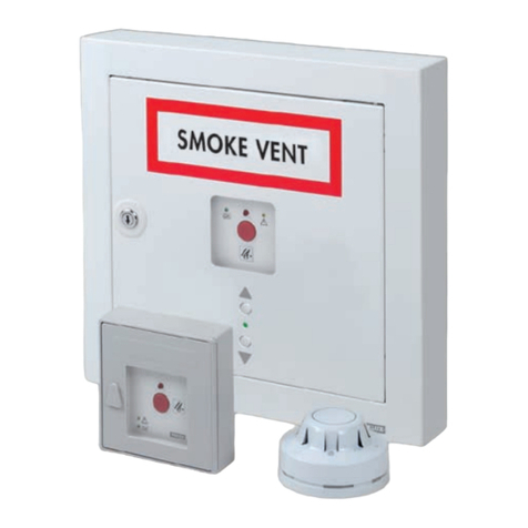
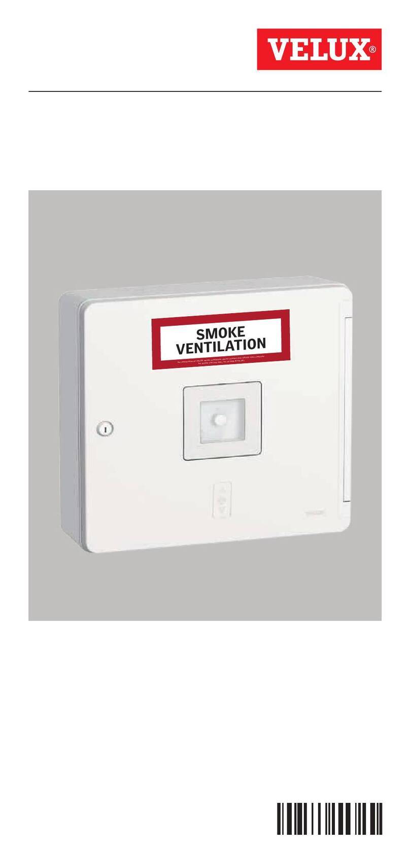
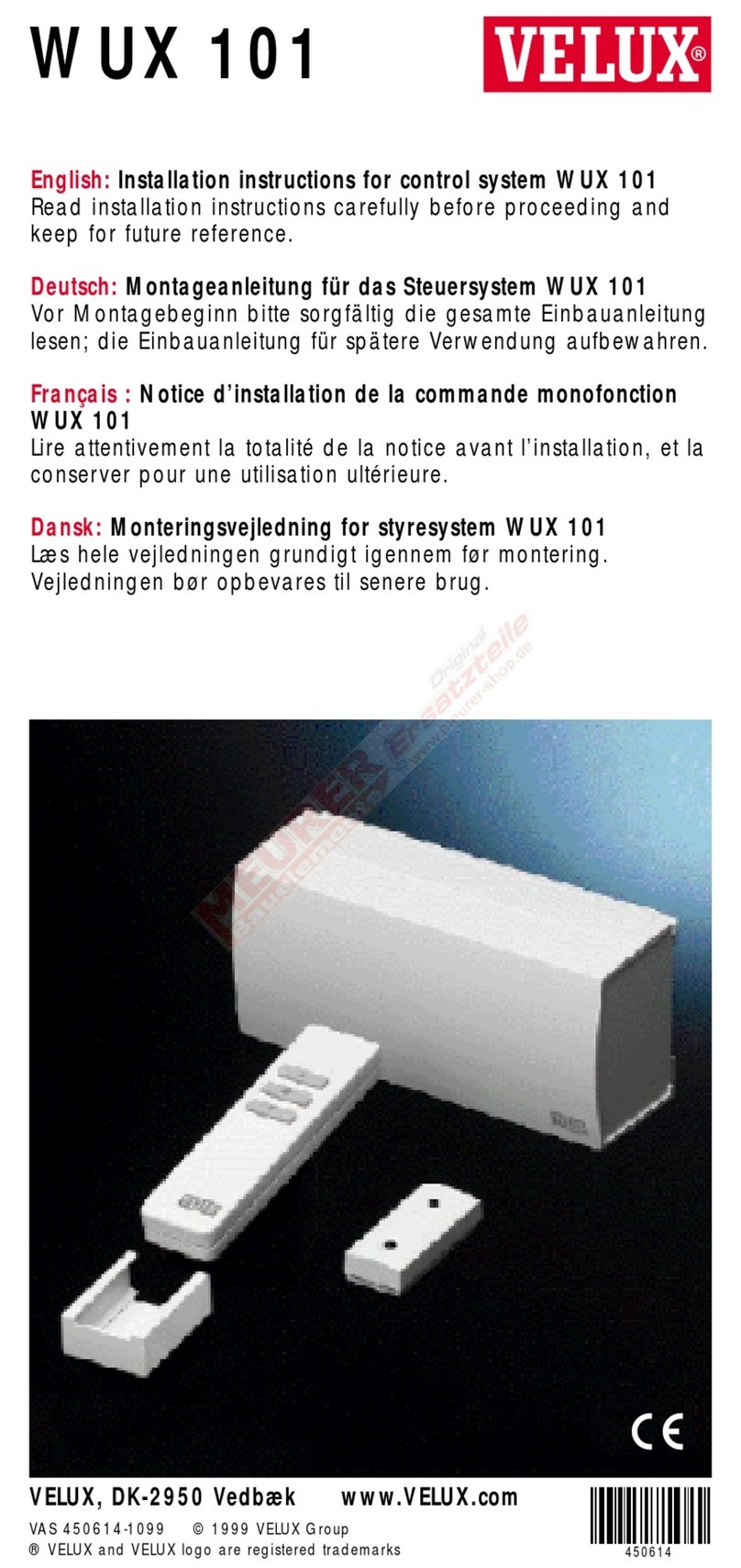
Velux KFX 210 User manual

VAS 453812-2019-11
KFX 210/211/212/213/214
KFC 210/220
For information on VELUX smokeventilation, please contact your VELUX sales company:
Tel. 01592 778 225 (UK),Tel. 01 848 8775 (IE)
SMOKE
VENTILATION
25-09-2014 07:44:14
Instructions for VELUX control
system for smoke ventilation
ENGLISH

2 VELUX®

VELUX®3
Important information 4-6
Contents of packaging 8-9
Overview of printed circuit board 10-11
Break-glass point KFK 100 12
Smoke detector KFA 100 13
Rain sensor KLA 200 14
Ventilation switch KFK 200 15
Motor terminals 16
Wiring 17
Setting of switches 18-19
Operation of and signals from control unit 20
Back-up batteries 21
Mains connection 22
Status and error indication in control system 23-25
Connected control units 26-31
- Transmit alarm from one control unit KFC to another 26
- Receive and transmit error indications
from one control unit KFC to another 27
- Ventilation switch 28
- Rain sensor 29
- Receive alarm from a primary, external control system 30
- Transmit alarms or error indications
to other external equipment 31
Replacement of frame in control unit 32
Technical data 33
Contents

4 VELUX®
Please read instructions carefully before proceeding and keep them for
future reference behind the battery holder inside the control unit.
Safety
• Control system for smoke ventilation
KFX 210/211/212/213/214 and control unit for
smoke ventilation KFC 210/220 can be used by
persons (aged 8 years and above) with sufficient
experience and knowledge if they have been given
instruction concerning safe use and understand
the hazards involved. Cleaning and user mainte-
nance must not be made by unsupervised chil-
dren.
• Children must not play with the control system.
• The installer must instruct the owner in the
function of the control system including reset-
ting of alarms and position of data plate and
instructions.
• The data plate is placed in the control unit.
• When resetting alarms, be sure not to touch
conductive parts and make sure that no body
parts can get caught in the window when reac-
tivated.
• WARNING! Make sure to use ESD protection
when touching the printed circuit board for
example during installation and service.
Important information

VELUX®5
Product
• The control system has been designed for use with genuine VELUX prod-
ucts. Connection to other products may cause damage or malfunction.
• The control system is in conformity with the Low Voltage Directive and
the EMC Directive for use in household, trade, industry and light industry.
• When installed, the control system complies with protection degree
IP 42.
• The control system can operate smoke ventilation windows with a total
power consumption of 10 A (KFC 210) and 2 x 10 A (KFC 220) respec-
tively.
• The packaging must be disposed of in accordance with national regula-
tions.
• Products, including batteries if any, marked with the crossed out
wheeled bin are regarded as electrical and electronic equipment and
contain hazardous materials, components and substances. The crossed
out wheeled bin symbolises that electrical and electronic equipment
waste must not be disposed of together with household waste. It must
be collected separately at recycling stations or other collection sites or
retrieved directly from households to increase the possibilities of recyc-
ling, reuse and utilisation of electrical and electronic equipment waste.
By sorting electrical and electronic equipment waste with this symbol,
you contribute to reducing the volume of incinerated or buried waste and
to reducing any negative impact on human health and the environment.
Further information can be obtained from the local municipality's techni-
cal administration or from your VELUX sales company.
• If batteries can be removed, product and batteries must be disposed of
separately.
Installation
• Installation must be carried out by a certified person in accordance with
current national regulations.
• The control system must be connected directly to the mains supply in ac-
cordance with national regulations. Ensure that the mains supply cannot
be disconnected unintentionally. It is recommended that disconnection
is only possible using the mains switch or a key switch. At least one of
these means for disconnection must be incorporated in the fixed wiring in
accordance with national wiring requirements.
Maintenance and service
• Disconnect mains supply and back-up batteries before carrying out any
maintenance or service work to the control system and ensure that they
cannot be reconnected unintentionally during this time.
• The control system must be tested after installation, service work and
alterations to the system. It must be inspected by qualified personnel at
least once a year. Tests and inspections must be documented in accord-
ance with national regulations.
• At the yearly inspection, the connected products must be checked ac-
cording to their instructions.
• The printed circuit board monitors the time between inspection periods.
If more than 15 months have passed since the last inspection, the yellow
light-emitting diode is on and an acoustic alarm sounds.
• The batteries must be checked at the yearly inspection. We recommend
that the batteries are replaced at least every four years.
• If you have any technical questions, please contact your VELUX sales
company, see telephone list or www.velux.com.
Important information

6 VELUX®
Declaration of Conformity
We herewith declare that the VELUX control systems for smoke
ventilation
KFX 210 (control unit 3FC F21 (model BD-SC001), smoke detector
KFA 100/3FA F01 and break-glass point KFK 100/3FK F00),
KFX 211 (control unit 3FC F21 (model BD-SC001), smoke detector
KFA 100/3FA F01 and break-glass point KFK 101/3FK F01),
KFX 212 (control unit 3FC F21 (model BD-SC001), smoke detector
KFA 100/3FA F01 and break-glass point KFK 102/3FK F02),
KFX 213 (control unit 3FC F21 (model BD-SC001), smoke detector
KFA 100/3FA F01 and break-glass point KFK 103/3FK F03),
KFX 214 (control unit 3FC F21 (model BD-SC001), smoke detector
KFA 100/3FA F01 and break-glass point KFK 104/3FK F04) and
VELUX control units for smoke ventilation KFC 210 (3FC F21 (model
BD-SC001)) and KFC 220 (3FC F22 (model BD-SC002-01))
− are in conformity with the provisions of Low Voltage Directive
2014/35/EU, EMC Directive 2014/30/EU and the RoHS Directive
2011/65/EU
− have been manufactured in accordance with the harmonised
standards EN 61000-3-2(2014), EN 61000-3-3(2013),
EN 55014-1(2006)+A1(2009)+A2(2011), EN 50130-4(2011),
EN 60335-1(2012)+A11(2014) and EN 62233(2008) and
− have been assessed in accordance with the harmonised standard
EN 50581(2012).
When one of the above-mentioned VELUX control systems or VELUX
control units are connected to a VELUX smoke ventilation window
GGL -K-- ----40, GGU -K-- ----40 or CSP, the total system is to be
considered as a machine, which is not to be put into service until it has
been installed according to instructions and requirements.
The total system then complies with the essential requirements of the
Council Directives 2014/35/EU, 2014/30/EU and 2006/42/EC.
The control systems and control units also comply with the Construction
Products Regulation (EU) No. 305/2011. For Declaration of Performance,
please go to www.velux.com.
VELUX A/S: . . . . . . . . . . . . . . . . . . . . . . . . . . . . . . . . . . . . . . . . . . . . . . . . . . . . . . . . . . .
(Jens Aksel Thomsen, Test Engineer, Market Approval)
Ådalsvej 99, DK-2970 Hørsholm. . . . . . . . . . . . . . . . . . . . . . . . . . . . . . . . . . . . . . . . . .
CE DoC 940402-02
11-11-2019

VELUX®7

8 VELUX®
9 10 11
x 10
EXTRACTOR DE HUMOR
RØGLEM
ROO
SMOKE VENT
ABV-CENTRAL
ESCAP
3
2
1
x 4
7
8
4
5
6
1Control unit for smoke ventila-
tion KFC 210 or KFC 220 – see
type designation in the control
unit.
2Frame with instructions
3Keys, rubber bushes, screws
and cable ties
4Labels
5Back-up batteries
6Battery holder
7Cables for batteries
8Blank lid
9Break-glass point
KFK 100-104*)
10 Smoke detector KFA 100*)
11 Coloured frame*)
*) Is delivered depending on type
of control system.
Contents of packaging

VELUX®9
1
ON
23456
Keep the instructions behind the battery holder in the control unit.
Stick the supplied label "SMOKE VENTILATION" onto the indicated area
on the control unit.

10 VELUX®
2132541
LINK
DET.21DET.21
NL
NL
PENL
230V
230V
ALARMMOTOR 2MOTOR 1230V/50Hz
24V
H I
M M
230 V
50 Hz
BA C
AMains connection 19
BMotor 1 14-15
CMotor 2 14-15
DSmoke detector 11
ERain sensor 12
FVentilation switch 13, 25
GBreak-glass point 10
HAlarm signals 23-24, 27-28
ILink 24
JRain signal - output 26
Overview of printed circuit board

VELUX®11
J1
65432132132121
132
+–
213213
FACU
BATTERY
ERROR-MOTOR 1
ERROR-MOTOR 2
ERROR-SMOKE DET.
ERROR-BREAK GLASS
RAIN SENSOR INPUT
ALARM ACTIVE
ERROR-TEMP. FUSE
MAINTENANCE
BATTERY
PSU2 OK
PSU1 OK
OPERATION
RESET
SETUP
RESET
73˚ C
TEMP. FUSE
TIME
AUTO CLOSE
TIME
OPENNIG
COMFORT
FRONT PANEL
BREAK GLASS POINTRAINRAIN IN COMFORTSMOKERAIN OUT ERROR
FUSE: 25A
+–
24V
1
ON
23456
D E F G
J K L M
P QO R SN
KRain signal - input 26
LFACU terminals 23, 27
MError indication 28
NBatteries 18
OComfort opening time 13
PAuto close time 13
QTemperature fuse 22
RStatus indications 20-22
SSetting 16

12 VELUX®
J1
65432132132121
132
+–
2132132132541
LINK FACU
BATTERY
DET.21DET.21
NL
NL
PENL
230V
230V
ERROR-MOTOR1
ERROR-MOTOR2
ERROR-SMOKE DET.
ERROR-BREAK GLASS
RAIN SENSOR INPUT
ALARM ACTIVE
ERROR-TEMP.FUSE
MAINTENANCE
BATTERY
PSU2 OK
PSU1 OK
OPERATION
RESET
SETUP
RESET
73˚ C
TEMP.FUSE
TIME
AUTOCLOSE
TIME
OPENNIG
COMFORT
FRONT PANEL
BREAK GLASS POINTRAINRAIN IN COMFORTSMOKERAIN OUT ERRORALARM
FUSE: 25A
MOTOR2MOTOR1230V/50Hz
+–
24V 24V
1
ON
23456
654321
678954321
J1
J1
9
a
b
Up to 10 break-glass points can be connected
to each control system.
Installation
Break-glass points KFK 100/101/102/103/104
are surface mounted and should be connected in
accordance with current national legislation. The
installation surface must be smooth and level.
Connection
The break-glass point is connected to the
control unit by means of a 6-core cable with a
minimum cross-section of 0.5 mm2. This cable
can be up to 100 m long.
Break-glass points KFK 100/101/102/103/104
must be installed in continuous single line con-
nections to ensure that the complete line from
the control unit to the last break-glass point
is monitored. Individual connection to more
than one break-glass point does not allow for
monitoring.
The first additional break-glass point must be
connected to the terminals in the control unit.
When connecting, lead cable through the rub-
ber membrane and fasten with cable tie.
Terminal module J1 (jumper)
Terminal module J1 in the control unit must be
moved to the last or only break-glass point – ie
to the break-glass point placed farthest away
from the control unit a.
Note: If no break-glass points are in the
system, the terminal module in the control unit
must be moved from the middle and lowest pin
to the top and middle pin b.
Colour of frame for break-glass point in
control unit
The white frame can be replaced by the
coloured frame supplied (applies to KFX 211,
212, 213 and 214 and KFC 210 and 220). See
page 32.
Break-glass point
KFK 100

VELUX®13
J1
65432132132121
132
+–
2132132132541
LINK FACU
BATTERY
DET.21DET.21
NL
NL
PENL
230V
230V
ERROR-MOTOR1
ERROR-MOTOR2
ERROR-SMOKE DET.
ERROR-BREAK GLASS
RAIN SENSOR INPUT
ALARM ACTIVE
ERROR-TEMP.FUSE
MAINTENANCE
BATTERY
PSU2 OK
PSU1 OK
OPERATION
RESET
SETUP
RESET
73˚ C
TEMP.FUSE
TIME
AUTOCLOSE
TIME
OPENNIG
COMFORT
FRONT PANEL
BREAK GLASS POINTRAINRAIN IN COMFORTSMOKERAIN OUT ERRORALARM
FUSE: 25A
MOTOR2MOTOR1230V/50Hz
+–
24V 24V
1
ON
23456
L1 in
L1 out L2
21
SMOKE
L1 in
L2
L2
L1 in
L1 out
L1 out
21
SMOKE
Up to 10 smoke detectors can be connected to
each control system.
Installation
Smoke detector KFA 100 should always be
fitted on the ceiling in accordance with current
national legislation. After fitting the base, the
smoke detector can be snapped into place.
Position dust cover over the smoke detector
until it is ready for operation.
Connection
The smoke detector is connected to the control
unit by means of a 2-core cable with a mini-
mum cross-section of 0.5 mm2. This cable can
be up to 100 m long.
Smoke detectors KFA 100 must be installed
in continuous single line connections to ensure
that the complete line from the control unit
to the last detector is monitored. Individual
connection to more than one break-glass point
does not allow for monitoring.
When connecting, lead cable through the rub-
ber membrane and fasten with cable tie.
Terminal module in control system
The terminal module in the control unit must be
moved to the last or only smoke detector – ie to
the smoke detector placed farthest away from
the control unit.
Smoke detector
KFA 100

14 VELUX®
J1
65432132132121
132
+–
2132132132541
LINK FACU
BATTERY
DET.21DET.21
NL
NL
PENL
230V
230V
ERROR-MOTOR1
ERROR-MOTOR2
ERROR-SMOKE DET.
ERROR-BREAK GLASS
RAIN SENSOR INPUT
ALARM ACTIVE
ERROR-TEMP.FUSE
MAINTENANCE
BATTERY
PSU2 OK
PSU1 OK
OPERATION
RESET
SETUP
RESET
73˚ C
TEMP.FUSE
TIME
AUTOCLOSE
TIME
OPENNIG
COMFORT
FRONT PANEL
BREAK GLASS POINTRAINRAIN IN COMFORTSMOKERAIN OUT ERRORALARM
FUSE: 25A
MOTOR2MOTOR1230V/50Hz
+–
24V 24V
1
ON
23456
321
RAIN
The product can be purchased separately.
Note: When fitting rain sensor KLA 200, use
the instructions supplied with the sensor.
Connection
The rain sensor is connected to the control unit
by means of a 3-core cable with a minimum
cross-section of 0.5 mm2. This cable can be up
to 100 m long.
Note: If the rain sensor has been activated, ie
has closed the window due to rain, it will take
at least 2 minutes before the comfort ventila-
tion can be activated again.
When connecting, lead cable through the rub-
ber membrane and fasten with cable tie.
Rain sensor
KLA 200

VELUX®15
J1
65432132132121
132
+–
2132132132541
LINK FACU
BATTERY
DET.21DET.21
NL
NL
PENL
230V
230V
ERROR-MOTOR1
ERROR-MOTOR2
ERROR-SMOKE DET.
ERROR-BREAK GLASS
RAIN SENSOR INPUT
ALARM ACTIVE
ERROR-TEMP.FUSE
MAINTENANCE
BATTERY
PSU2 OK
PSU1 OK
OPERATION
RESET
SETUP
RESET
73˚ C
TEMP.FUSE
TIME
AUTOCLOSE
TIME
OPENNIG
COMFORT
FRONT PANEL
BREAK GLASS POINTRAINRAIN IN COMFORTSMOKERAIN OUT ERRORALARM
FUSE: 25A
MOTOR2MOTOR1230V/50Hz
+–
24V 24V
1
ON
23456
321
COMFORT
Min Max
TIME
AUTO CLOSE
TIME
OPENNIG
COMFORT
Up to 10 ventilation switches can be connected
to each control system.
The product can be purchased separately.
Connection
The ventilation switch is connected to the
control unit by means of a 3-core cable with a
minimum cross-section of 0.5 mm2. This cable
can be up to 100 m long.
Output 1: Open
Output 2: Close
Output 3: Common
When connecting, lead cable through the rub-
ber membrane and fasten with cable tie.
Setting of timers
COMFORT OPENING TIME
The time taken for the window to open (in sec-
onds) can be set when the window is opened
for comfort ventilation purposes (factory set-
ting is about 12 seconds).
Note: The window must not be opened more
than 20 cm.
Min duration: 5 seconds
Max duration: 60 seconds
AUTO CLOSE TIME
Automatic closing of windows opened for
comfort ventilation purposes can also be set.
This function is only active if switch 4 is set in
position ON (see page 19).
Min opening time: 2 minutes
Max opening time: 60 minutes
Ventilation switch
KFK 200

16 VELUX®
J1
65432132132121
132
+–
2132132132541
LINK FACU
BATTERY
DET.21DET.21
NL
NL
PENL
230V
230V
ERROR-MOTOR1
ERROR-MOTOR2
ERROR-SMOKE DET.
ERROR-BREAK GLASS
RAIN SENSOR INPUT
ALARM ACTIVE
ERROR-TEMP.FUSE
MAINTENANCE
BATTERY
PSU2 OK
PSU1 OK
OPERATION
RESET
SETUP
RESET
73˚ C
TEMP.FUSE
TIME
AUTOCLOSE
TIME
OPENNIG
COMFORT
FRONT PANEL
BREAK GLASS POINTRAINRAIN IN COMFORTSMOKERAIN OUT ERRORALARM
FUSE: 25A
MOTOR2MOTOR1230V/50Hz
+–
24V 24V
1
ON
23456
DET.21
MOTOR 1
M
DET.21
MOTOR 1
M
M
DET.21DET.21
MOTOR 2MOTOR 1
D
ET
.
2
1
M
O
T
O
R
2
DET.21DET.21
MOTOR 2MOTOR 1
Each terminal is intended for 24 V DC and max 10 A.
Control unit KFC 210 (10 A)
In this example, only motor terminal 1is active.
Max 4smoke ventilation windows
GGL/GGU -K-- ----40
or
1smoke ventilation window CSP can be con-
nected to the control unit.
Control unit KFC 220 (2 x 10 A)
In this example, both motor terminals 1and 2are
active.
Max 8smoke ventilation windows
GGL/GGU -K-- ----40 (max 4windows per motor
terminal)
or
2smoke ventilation windows CSP can be con-
nected to the control unit.
Terminal module
To ensure cable monitoring, the terminal module
in the control unit must be moved to the last con-
nection between smoke ventilation windows
GGL/GGU -K-- ----40 or CSP and the cables from
the control unit.
Note: In case motors operate in the wrong direc-
tion, transpose the 2 motor cables in the terminal.
Motor terminals

VELUX®17
J1
65432132132121
132
+–
2132132132541
LINK FACU
BATTERY
DET.21DET.21
NL
NL
PENL
230V
230V
ERROR-MOTOR1
ERROR-MOTOR2
ERROR-SMOKE DET.
ERROR-BREAK GLASS
RAIN SENSOR INPUT
ALARM ACTIVE
ERROR-TEMP.FUSE
MAINTENANCE
BATTERY
PSU2 OK
PSU1 OK
OPERATION
RESET
SETUP
RESET
73˚ C
TEMP.FUSE
TIME
AUTOCLOSE
TIME
OPENNIG
COMFORT
FRONT PANEL
BREAK GLASS POINTRAINRAIN IN COMFORTSMOKERAIN OUT ERRORALARM
FUSE: 25A
MOTOR2MOTOR1230V/50Hz
+–
24V 24V
1
ON
23456
CSP
Electrical cables should be drawn according to regulations by qualified per-
sonnel. The control system and its cables should be installed in compliance
with current national legislation and the requirements of local authorities.
Maximum cable length/prescribed cross-sectional size of
cables
The maximum allowed cable lengths between control unit and motor and the
prescribed cross sectional sizes of the cables are given in the table below. The
cable must be protected according to National/European Standards.
Calculation of max. cable length: 56 x A/l
Ais cable cross-section and Iis max motor current in total.
Allowed maximum voltage drop in the cable: 2 V
Operation current: The total of all motor currents.
Cable cross-section per motor terminal for smoke ventilation window
GGL/GGU -K-- ----40
Cable cross-section per motor terminal for smoke ventilation window CSP
Wiring
Cable cross-
section
Max. cable length for
number of motors *)
1234
3 x 1.5 mm2 33 m 16 m 11 m 8 m
*) 5 x 1.5 mm267 m 33 m 22 m 16 m
3 x 2.5 mm256 m 28 m 18 m 14 m
*) 5 x 2.5 mm2112 m 56 m 37 m 28 m
3 x 4 mm289 m 44 m 29 m 22 m
3 x 6 mm2134 m 67 m 44 m 33 m
Cable cross-
section
Max. cable length *)
3 x 1.5 mm28 m
*) 5 x 1.5 mm217 m
3 x 2.5 mm214 m
*) 5 x 2.5 mm228 m
3 x 4 mm222 m
3 x 6 mm233 m
*) 2x2 conductors in parallel
Only one smoke ventilation window CSP per motor
terminal
*) 2x2 conductors in parallel

18 VELUX®
J1
65432132132121
132
+–
2132132132541
LINK FACU
BATTERY
DET.21DET.21
NL
NL
PENL
230V
230V
ERROR-MOTOR1
ERROR-MOTOR2
ERROR-SMOKE DET.
ERROR-BREAK GLASS
RAIN SENSOR INPUT
ALARM ACTIVE
ERROR-TEMP.FUSE
MAINTENANCE
BATTERY
PSU2 OK
PSU1 OK
OPERATION
RESET
SETUP
RESET
73˚ C
TEMP.FUSE
TIME
AUTOCLOSE
TIME
OPENNIG
COMFORT
FRONT PANEL
BREAK GLASS POINTRAINRAIN IN COMFORTSMOKERAIN OUT ERRORALARM
FUSE: 25A
MOTOR2MOTOR1230V/50Hz
+–
24V 24V
1
ON
23456
4635
21
ON
SETUP
4635
21
ON
SETUP
4635
21
ON
SETUP
4635
21
ON
SETUP
4635
21
ON
SETUP
4635
21
ON
SETUP
4635
21
ON
SETUP
3
2
1
ON
5
4
5
Setting of switches
Cable errors are indicated by the yellow light-
emitting diode that flashes on and off and an
acoustic alarm from control unit and connected
break-glass points.
(Factory setting).
Remove thin foil before setting the switches, if
necessary (1-6).
No external fire alarm is connected to FACU
terminal (FACU = Fire Alarm Control Unit).
(Factory setting).
If an alarm is activated via a smoke detector, the
window opens fully.
(Factory setting).
Cable errors are indicated by the red light-emit-
ting diode and an acoustic alarm from control unit
and connected break-glass points, and windows
open.
An external fire alarm is connected to FACU ter-
minal and the cable connection is monitored.
If an alarm is activated via a smoke detector, all
windows that are open (in comfort ventilation
position) close.
Note: If an alarm is activated via a break-glass
point, all windows open.
Switch 1
Switch 2
Switch 3

VELUX®19
J1
65432132132121
132
+–
2132132132541
LINK FACU
BATTERY
DET.21DET.21
NL
NL
PENL
230V
230V
ERROR-MOTOR1
ERROR-MOTOR2
ERROR-SMOKE DET.
ERROR-BREAK GLASS
RAIN SENSOR INPUT
ALARM ACTIVE
ERROR-TEMP.FUSE
MAINTENANCE
BATTERY
PSU2 OK
PSU1 OK
OPERATION
RESET
SETUP
RESET
73˚ C
TEMP.FUSE
TIME
AUTOCLOSE
TIME
OPENNIG
COMFORT
FRONT PANEL
BREAK GLASS POINTRAINRAIN IN COMFORTSMOKERAIN OUT ERRORALARM
FUSE: 25A
MOTOR2MOTOR1230V/50Hz
+–
24V 24V
1
ON
23456
463 5
21
ON
SETUP
4635
21
ON
SETUP
4635
21
ON
SETUP
463 5
21
ON
SETUP
4635
21
ON
SETUP
4635
21
ON
SETUP
Setting of switches
Automatic, time controlled closing of comfort
ventilation is off.
(Factory setting).
Battery monitoring is on.
(Factory setting).
N/A (No function)
Automatic, time controlled closing of comfort
ventilation is on.
The time is set by means of the timer "AUTO
CLOSE TIME", see section Ventilation switch KFK
200.
Note: When the battery is low, the light-emitting
diode flashes on and off. If the service technician
decides to turn off the diode, the battery monito-
ring is also off.
Battery monitoring is off.
N/A (No function)
Switch 4
Switch 5
Switch 6

20 VELUX®
Break-glass point
In case of fire: Break the glass cover and press the red
button. All windows connected to the control system
open. The red light-emitting diode over the red button in
the control unit is on and an acoustic alarm sounds. All
ventilation and rain sensor functions are disengaged.
Yellow light-emitting diode
In case of system errors, the yellow light-emitting diode
flashes on and off and an acoustic alarm sounds. Error
indication occurs, if cables for motors, break-glass
points or smoke detectors are interrupted or short-
circuited, or if the batteries are defective. If additional
break-glass points are connected, the corresponding
diodes in these will also flash on and off and an acoustic
alarm sounds.
Additional information on error causes can be seen on
the printed circuit board in the control unit. See section
Status and error indications in control system.
Green light-emitting diode
Under normal operation conditions, the green light-
emitting diode in the control unit is on. All other light-
emitting diodes are off. If additional break-glass points
are connected, the corresponding diodes in these will
also be on.
Open
Stop
Close
Operating buttons for comfort ventilation
A short press of the top ventilation button opens the
window to max comfort ventilation position.
A short press of the bottom ventilation button closes
the window completely.
By pressing and holding the top or bottom ventilation
button, the window opens/closes until the button is
released.
By pressing the stop button or by pressing the top and
bottom buttons simultaneously, the window stops.
By means of the timers in the control unit it is possible
to set the duration of the opening when the window is
opened for comfort ventilation and set automatic closing
of the window. See section Ventilation switch KFK 200.
Note: If a rain sensor is fitted, the comfort ventilation
function will automatically be blocked if rain is detected.
Operation of and signals
from control unit
Other manuals for KFX 210
1
This manual suits for next models
23
Table of contents
Other Velux Control System manuals

Velux
Velux Integra Kux 110 User manual

Velux
Velux KUX 100 User manual

Velux
Velux ACTIVE KIX 300 User manual

Velux
Velux KUX 100 User manual

Velux
Velux KFX 210 User manual

Velux
Velux KFX 110 User manual

Velux
Velux WUX 101 User manual

Velux
Velux Integra Kux 110 User manual

Velux
Velux KFX 100 User manual

Velux
Velux Vario User manual
Popular Control System manuals by other brands

Nuvation Energy
Nuvation Energy High-Voltage BMS installation guide

Murphy
Murphy MGC2000 Installation and operation manual

Safe Barriers
Safe Barriers Defender 100LDS installation manual

Norac
Norac UC4.5 installation manual

GCS
GCS CYSCAN Installation and maintenance guide

Homa
Homa PCM Series Original instruction manual