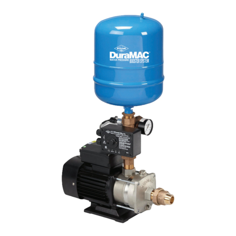
MCDonald DuraMAC SIMPLEX User guide

1
3/18 3210-552
ATTENTION!
Important information for installers of this equipment!
This equipment is intended for installation by technically qualied personnel. Failure to install it in compliance with
national and local electrical codes and with motor suppliers recommendations, may result in electrical shock or re
hazard, unsatisfactory performance, and equipment failure.
WARNING!
Serious or fatal electrical shock may result from failure to connect the motor, control enclosures, metal plumbing, and all
other metal near the motor or cable, to the power supply ground terminal using wire no smaller than motor cable wires. To
reduce risk of electrical shock, disconnect power before working on or around the water system.
WARNING: It is unlawful in CALIFORNIA & VERMONT (effective 1/1/2010); MARYLAND (effective 1/1/2012); LOUISIANA (effective 1/1/2013) and the UNITED STATES OF
AMERICA (effective 1/4/2014) to use any product in the installation or repair of any public water system or any plumbing in a facility or system that provides water for human
consumption if the wetted surface area of the product has a weighted average lead content greater than 0.25%. This prohibition does not extend to service saddles used in
California, Louisiana or under USA Public Law 111-380. WARNING: This product can expose you to chemicals including lead, which is known to the State of CALIFORNIA to
cause cancer and birth defects or other reproductive harm. For more information go to: www.P65Warnings.ca.gov.
Installation and Operating Instruction
DuraMACTM
Vertical Multi-Stage Centrifugal Pumps
WATER PRESSURE BOOSTER SYSTEM
Manual - Variable Speed Booster Systems
Simplex
Duplex
Triplex

23210-552 3/18
Table of Contents
1. Installation................................................................................................................................................................2
1.1 Mechanical ...................................................................................................................................................3
1.2 Electrical ......................................................................................................................................................3
1.3 Priming .........................................................................................................................................................3
2. Programming Functions...........................................................................................................................................4
2.1 Getting Started .............................................................................................................................................4
2.2 Home Screen .................................................................................................................................................4
2.3 Change Setpoint ...........................................................................................................................................5
2.4 Alarms and Faults ........................................................................................................................................5
2.5 How to Change Parameters ..........................................................................................................................5
2.6 Start / Draw Down Level ...............................................................................................................................6
2.7 Sleep Boost ...................................................................................................................................................6
2.8 Automatic Restart ........................................................................................................................................6
2.9 High Discharge Pressure ..............................................................................................................................7
2.10 Low Discharge Pressure ..............................................................................................................................7
2.11 Low Suction Pressure ..................................................................................................................................8
2.12 Backup Parameters ....................................................................................................................................9
2.13 Reset Parameters to Factory Default ..........................................................................................................9
3. Troubleshooting......................................................................................................................................................10
General Troubleshooting ...................................................................................................................................10
4. Wiring Diagrams .....................................................................................................................................................11
4.1) Simplex 230V Single Phase .......................................................................................................................11
4.2) Duplex 230V Single Phase .........................................................................................................................12
4.3) Simplex 230V Three Phase ........................................................................................................................13
4.4) Duplex 230V Three Phase ..........................................................................................................................14
4.5) Triplex 230V Three Phase ...........................................................................................................................15
4.6) Simplex 460V Three Phase ........................................................................................................................16
4.7) Duplex 460V Three Phase ..........................................................................................................................17
4.8) Triplex 460V Three Phase ...........................................................................................................................18
1. Installation
DuraMACTM booster systems are shipped in a wooden frame/cardboard box and are designed to be lifted from the bottom by fork truck
only. Care should be taken when unboxing the system to prevent damage. Any shipping damage should be reported to the shipping
carrier and local product dealer. Claims for shipping damage must be made through the shipping carrier.
Check system nameplate and verify that the model number is correct. Also conrm that voltage, phase, and horsepower are accurate.
For maintenance of the pump and/or motor, see instruction sheet 3210-528, DuraMACTM Vertical Multi Stage Centrifugal pumps.

3
3/18 3210-552
1.1 Mechanical
Do not lift pump system by the motor eyebolts or the intake/outlet manifolds. Use lifting straps suitable for the system
weight. Straps should be secured around the pump or system base. Use Caution.
The booster system must be installed in a well ventilated area without excess dust or moisture. The booster system should be bolted
directly to the oor using the supplied base holes. If noise and vibration is a concern, the booster system can be mounted using a
rubber gasket between the oor and base.
Expansion joints can help reduce noise and vibration transmitted through the outlet piping to the downstream user. In addition,
expansion joints can reduce the stress on suction and outlet piping associated with system misalignment during installation.
The suction and outlet piping should be of similar size of the booster system. On Duplex systems, either end of the manifold may be
used. The unused end should be capped using a ange cap.
A diaphragm pressure tank is required on the outlet piping close to the pump. Sizing of the tank is dependent on the ow capacity
of the system. A good rule of thumb is the tank size should be a minimum 25% of the maximum ow of the system. For example, a
duplex system with a maximum ow of 240 gpm should use a minimum 60 gallon tank. The tank pressure should be 15 psi below
the set point.
1.2 Electrical
All electrical connections and installation must be carried out be a licensed electrician in accordance with all national
and local codes and regulations.
The electrical supply should match that as stated on the booster system label. See wiring diagrams in section 3 for electrical
connections, minimum wire sizes, and fuse types.
1.3 Priming
- Flooded Suction Systems
- Flooded suction systems have either an incoming supply pressure or an elevated holding tank. Ensure that all suction valves
are open and that the pump discharge valve is closed. Open the small vent plug on top of the pump. Air and spurts of water
will spray out. Close the vent plug when a steady stream of water is owing.
- Suction Lift Systems
- Suction lift systems should have a foot check valve on the suction line at the water source. The pump discharge valve should
be closed at this time. A ll point near the pump system inlet is recommended to ensure the entire suction line can be lled
with water. Remove the large vent plug on the pump(s) and ll completely with water. Replace vent plug and ensure entire
inlet piping is pressure tight.
- System Priming
- The system may now be primed by starting the Yaskawa drive in HAND mode and slowly opening up the discharge valve(s).
Do not fully open the discharge valve until all the air has been purged from the lines. After all system lines have been lled
with water, the discharge valve may be completely opened. The system may now be started by pressing the key.
Do not operate against a closed discharge valve for more than three minutes as pump overheating and damage
may occur.

43210-552 3/18
2. Programming Functions
2.1 Getting Started
The Yaskawa iQpump 1000 drive features powerful software combined with an internal PLC to deliver multiple features that are designed
help protect the drive, pump, motor, and entire pumping system. While many of these features are factory programmed and set, many
features depend on the specic pumping application and may be required to be set during install.
Changing certain parameters while the drive and pump are running may cause unwanted behavior. It is recommended to turn
the drive off before changing parameter values.
2.2 Home Screen
To return to home screen, hold for 3 seconds, or press . The display should look similar to the one below. Once at the
home screen, additional drive status can be viewed by pressing . Additional drive information includes output frequency,
current, voltage, DC bus voltage, and kilowatts.
Digital Operator Keypad Alarm light blinks if alarm or
fault occurs
Pump Output Frequency
Press to turn AUTO mode on.
If LED is blinking, Auto mode is
active but pump is sleeping.
Transducer Feedback
(Actual System Pressure)
System Outlet Pressure Auto
Setpoint
Press to turn HAND mode
on. Use only for Priming and
troubleshooting. Pump will
run at a xed speed.
Do not run against a closed
discharge.
Press to turn system off.

5
3/18 3210-552
2.3 Change Pressure Set Point
Return to the Home Screen.
Press , and Setpoint 1 (Q1-01) should be displayed on screen. Use to scroll to the correct digit and
to change the setpoint value. Press to save the value and to return to the home screen.
This step must be performed on each drive for systems with multiple pumps. All drives must have identical
set points.
2.4 Alarms and Faults
The iQpump 1000 drive features two levels of protection and warnings to the operator.
An ALARM allows the system to continue running, but displays a warning on the digital operator screen and ashes the red alarm LED.
A FAULT stops the drive, displays the time and type of fault, and lights the red alarm LED. For most faults, the drive will attempt to restart
after certain time period or after the fault condition has been removed. After ve restart attempts without a successful start, the drive will
remain off in a fault mode until the problem is xed.
To clear a fault and restart the system, press , then . The pump will attempt to restart if all fault conditions have
been cleared.
Note: Real time clock is used to log all fault events with a date and time stamp for system troubleshooting. By default, the time is set
to Eastern Time EST (GMT – 5). To set the clock to local time, go to programming menu and modify parameter O2-17. The real time clock
does not support daylight savings time.
2.5 How to Change Parameters
From the home screen, use to access programming screen (screenshot left). Press to select.
Change to the desired parameter number by using the keys to change the selected character
value, and to switch to the next character. Repeat for the next two number values to set the parameter
number. To return to the previous character, press .
Change the desired parameter value by using the key to select the correct digit and the
keys to modify the digit value. Press to save the changed value. Return to the home screen after all
required parameters have been changed.
For systems with multiple pumps and multiple drives, all changed parameters should be identical on every drive.
Parameters changed on one drive are NOT automatically changed on other drives. All modied parameters
(including setpoint) must be changed on EACH drive to ensure correct operation of the system.
DUPLEX
TRIPLEX
DUPLEX
TRIPLEX

63210-552 3/18
2.6 Start / Draw Down Level
The start/draw down level is the value at which the system will start the pumps to build pressure. This allows the system to sleep longer
and prevent excessive cycling. If (P1-04) is positive, the system will start when the discharge pressure falls below this absolute value
(P1-04) and after a delay (P1-05) has elapsed. If this value is a negative number (-P1-04), the discharge pressure must fall that amount
below the setpoint before starting the system.
By default, the system will start when the discharge pressure drops 10 psi (P1-04) below the setpoint after delaying 1 second (P1-05).
If the Start/Draw Down Level is modied from factory defaults, the pressure tank air precharge must be set 5 psi below the start pressure.
For example, a system with a 60 psi setpoint (Q1-01) and a -15 psi draw down level (P1-04), the tank precharge air pressure must be set
at 40 psi. Ensure water pressure is zero when adjusting and measuring the precharge air pressure.
2.7 Sleep Boost
This parameter sets the amount of pressure boost (P2-05) that will be applied to the system setpoint before going to sleep. This setting
allows longer sleep times and less pump cycling.
By default, when the system goes to sleep, it will boost the system pressure by 5 psi (P2-05) above the system setpoint.
To disable sleep boost, set (P2-05) to 0.
2.8 Automatic Restart
In the event of a power supply loss or failure, the system is automatically programmed to restart once power has been restored.
To disable this function, set (P4-10) to a value of 0:Disabled.
Parameter Value Name Description
P1-04 -10 (psi) Start / Draw
Down Level
The system will start when the discharge pressure falls below this value
when sleeping. If this is a negative number, the start point is this value
amount below the setpoint.
RANGE: (-999 to 999 psi)
P1-05 1 (s) Start Level
Delay Time
After the system discharge pressure falls below P1-04, the system will
start after this time delay.
RANGE: (0-3600)
Parameter Value Name Description
P2-05 5 (psi) Sleep Boost
Level
The system will boost the outlet pressure by this amount before going
to sleep.
RANGE: (0-6000 psi)
Parameter Value Name Description
P4-10 1
Enabled
AMO PwDn- Storage
The system will automatically restart from a power failure once power
is restored. The pumps may start automatically based upon need.
RANGE: (0:Disabled, 1:Enabled)

7
3/18 3210-552
2.9 High Discharge Pressure
When the discharge feedback signal rises above the high feedback detection level (P1-11) for a specied time (P1-12), the system will
respond based on the actions in (P1-13).
By default, the drive will fault (P1-13) if the pressure rises above 150 psi (P1-11) for longer than 5 seconds (P1-12). The drive will
attempt to restart (L5-41) if the pressure falls below the high feedback level.
*NOTE: Some higher pressure Variable Speed Booster Systems feature a 200 psi discharge transducer and gauge. These models will
have the High Feedback Level (P1-11) factory set at 200 psi.
Parameter Value
(Factory Set)
Name Description
L5-41 1High Feedback
Retry
Determines if the drive will attempt to restart after a High Feedback
Level Fault has occurred.
RANGE: (0: No Retry, 1: Retry)
P1-11 *150 (PSI) High Feedback
Level
The iQpump will display a “High Feedback/Water (HFB/HW) alarm
when pump output rises above this number. If the high feedback
continues for the time period specied in P1-12, a fault will occur and
the pump will stop
RANGE: (0-6000 psi)
P1-12 5 (s) High Feedback
Level Fault Delay
Time
Time period that the High Feedback Alarm must be activated before a
fault occurs.
RANGE: (0-3600 s)
P1-13 0: Fault High Feedback
Selection
Selects drive response when outlet pressure rises above High Feed-
back Level (P1-11) and High Feedback Delay Time (P1-12) has
elapsed.
RANGE: (0: Fault, 1: Alarm, 2: Digital Output)
2.10 Low Discharge Pressure
When the discharge feedback signal falls below the low feedback detection level (P1-08) for a specied time (P1-09), the system will
respond based on the actions in (P1-10).
By default, the drive will fault (P1-10) if the pressure falls below (P1-08) for longer than 10 seconds (P1-09). The drive will attempt to
restart (L5-40) if the pressure rises above the low feedback level.
To disable the low outlet pressure, set (P1-10) to 1:Alarm.
Parameter Value Name Description
L5-40 1Low Feedback
Retry
Determines if the drive will attempt to restart after a Low Feedback
Level Fault has occurred.
RANGE: (0: No Retry, 1: Retry)
P1-08 *10 (PSI) Low Feedback
Level
The iQpump will display a “Low Feedback/Water (LFB/LW) alarm
when pump output falls below this number. If the low feedback
continues for the time period specied in P1-09, a fault will occur
and the pump will stop.
RANGE: (0-6000 psi)
P1-09 10 (s) Low Feedback
Level Fault Delay
Time
Time period that the Low Feedback Alarm must be activated before a
fault occurs.
RANGE: (0-3600 s)
P1-10 0: Fault Low Feedback
Selection
Selects drive response when outlet pressure falls below Low Feed-
back Level (P1-08) and Low Feedback Delay Time (P1-09) has
elapsed.
RANGE: (0: Fault, 1: Alarm, 2: Digital Output)

83210-552 3/18
2.11 Low Suction Pressure
When the suction feedback signal falls below the minimum suction setpoint (Q5-03), the system will respond by slowing down the pump to
maintain incoming pressure. If the suction pressure continues to fall below the minimum suction pressure (Q5-04) for a specied time (Q5-
05), the system will respond by going to sleep. For multiple pump applications, all other pumps will also go to sleep mode. After the suction
pressure has risen above the wake up pressure (Q5-06), the drive will restart the pump(s) automatically and return to normal auto operation.
By default, this feature is turned off. To enable this feature, set parameter (Q5-01) to 1: Enabled. The drive will slow down the pump(s) when
the suction pressure reaches 10 psi (Q5-03). The system will go to sleep when the suction pressure falls below 5 psi (Q5-04) for more than 5
seconds (Q5-05). Once the suction pressure has risen above 10 psi (Q5-06), the drive will restart and return to normal operation. To disable the
low suction pressure, set (q5-01) to 0:Disabled.
Parameter Value Name Description
Q5-01 0 Suction Pressure Select
Sets the method of operation for the Suction Control / Vacuum Control
Function
RANGE: (0: Disabled, 1: Suction Pressure, 2: Vacuum {“Hg})
Q5-02 150 (PSI) Suction
Scaling
Sets the full scale of the 4-20 {mA} suction transducer that is connected
to the analog input terminal A1.
RANGE: (0-1200)
Q5-03 10 (PSI) Minimum Suction
Setpoint
The level below which the drive will slow down the pump(s) to try to
maintain incoming pressure.
RANGE: (0-1200 PSI)
Q5-04 5 (PSI) Minimum Suction
Pressure
The level below which the drive will go to sleep and turn off all other lag
pumps.
RANGE: (0-1200 PSI)
Q5-05 5 (s) Suction Pressure Sleep
Delay Time
Sets the length of time the drive will delay after the suction pressure falls
below the minimum suction pressure (Q5-05) before the drive will go to
sleep.
RANGE: (0-3600 s)
Q5-06 10 (PSI) Wake Up Pressure
Sets the pressure that the suction must rise above to restart normal pump
operation.
RANGE: (0-1200 PSI)

9
3/18 3210-552
2.12 Backup Parameters
BACKUP
To save a backup of all parameters, set parameter o3-01 to value of 1. This will save the parameters to the digital operator keypad.
2.13 Reset Parameters to Factory Default
To reset parameters to the A.Y. McDonald factory default, set parameter (A1-03) to 1110: User Initialize
RETRIEVE
To reset drive parameters to the backup parameters, set parameter o3-01 to a value of 2. This will copy parameters from the digital
operator keypad to the active drive parameters, overwriting any changes made to the drive parameters.
WARNING: Retrieving parameters from the digital operator keypad without rst performing a backup will result in drive parameters
being reset to the A.Y. McDonald factory default.
Parameter Value Name Description
o3-01 1 Copy Select
Inv>Op Read
Copies parameters from the drive and stores them on the Digital
Operator Keypad
Parameter Value Name Description
A1-03 1110 User Initialize 1110 Returns parameters to AY McDonald factory default values.
Parameter Value Name Description
o3-01 2 Copy Select
Op>Inv Write
Copies parameters from the Digital Operator Keypad and writes
them to the drive as the active parameters

10 3210-552 3/18
Problem How To Check Solution
iQpump is on AUTO, green LED is
blinking, pump is not running.
iQpump is sleeping. System demand is low. Once the outlet pressure has fallen below
the start/draw down level, the iQpump will start the pump.
Water is leaking from around
motor/pump coupling
Turn system off. Remove motor coupling
guards. Observe mechanical seal for
leaks.
Replace mechanical seal. See Pump manual 3210-528.
Alarm light is blinking and
Digital Operator Display
indicates Alarm.
Review code and error displayed on
screen. Take appropriate actions to x
the alarm problem.
If problem still persists, call factory for alarm troubleshooting.
Alarm light is lit and Digital
Operator Display indicates Fault.
Review code and error displayed on
screen. Take appropriate actions to x
the faults.
Turn power off to the system using the disconnect. Wait 20
seconds and turn power back on. Press the RESET key, and then
press AUTO to restart the system. If the fault re-occurs, call
factory for fault troubleshooting.
Problem How To Check Solution
Pressure tank too small Pressure tank size should a minimum 25% of
total booster ow. A booster system delivering a
maximum of 240 gpm should have a minimum tank
size of 60 gallons.
Replace or add additional pressure tanks.
Incorrect air pressure in tank For discharge or bladder captive air tanks, drain the
tank of water and check the precharge air pressure.
It should be 15 psi below the pressure setpoint.
Fill precharge air pressure in tank to specied value (ensure
water pressure is zero). Replace tank if it will not hold air
pressure.
Increase Start/Draw Down
Level
Refer to Section 2.7. Sleep boost increases the
setpoint pressure before putting the system to
sleep.
Increase the (negative) valve of P1-04. The pressure tank
precharge level may need to be adjusted.
Transducer valves closed or
transducer piping blocked
Verify that pressure feedback (U1-91) on home
screen matches discharge pressure gauge. If the
two are more than 5 psi apart, ensure all test valves
on transducers are open and there is no blockage in
piping.
Open all test valves on transducer piping. Clear any
blockage. If problem still persists, replace transducer.
Problem How To Check Solution
Bypass line/valve open Locate bypass valve (if applicable) . Ensure valve is
completely in the closed position
Close valve entirely.
Pump Isolation Valves are
closed
Locate pump isolation valves located on the inlet
and outlet of each pump. Both valve handles should
in the open position
Open valves entirely (parallel with pump).
Pump may be air locked Locate the purge port located on top of the pump.
Loosen the smaller hex bolt slightly. Listen for air
escaping.
Keep purge port open until all air has been evacuated and
a steady stream of water is owing. Close purge port.
Pump may have lost Prime Check suction pipes, check valves, and foot valves
for leaks.
Ensure suction piping is pressure tight. Replace check
valves or foot valves as necessary. Re-prime as needed
using the pump ll port.
Shaft Coupling loose Turn system off and switch disconnect to “OFF”
position. Remove shaft cover and inspect motor
coupling.
If loose, refer to maintenance section of Manual 3210-528
for correct shaft coupling reassembly.
Motor operating in wrong
direction
View motor direction from top. Motor should turn in
direction of arrow on pump.
If backwards, switch any two motor leads at the drive.
Ensure drive is off, power is removed, and charge indicator
has been extinguished before removing terminal cover.
3. Troubleshooting
General Troubleshooting
Problem: Pump is running but does not deliver water
Problem: Pump short cycles or continues to run

11
3/18 3210-552
4.1 Simplex 230V Single Phase
SIMPLEX
230V SINGLE PHASE 3 - 5 HP
Wire Size
HP Supply Motor FUSES
3 10 GA 10 GA 30A CC
5 8 GA 8 GA 60A J
Notes:
1) Time Delay Fuses (See Chart)
2) Shielded Transducer Cables
3) Supply Wire (See Chart)
4) Motor Wire (See Chart)
4. Wiring Diagrams
The attached wiring diagrams show the electrical connections for various DuraMAC Variable Speed Booster Systems. Select the proper
wiring diagram for the model you are installing. These wiring diagrams show factory installed wiring and are used for reference only. Use
appropriate supply wire size for the rated current, voltage, and length of wire. Always use good wiring practices and follow all local and
state wiring codes. Ensure all equipment is grounded properly.
The iQpump 1000 drive contains lethal voltages. Before removing the drive terminal cover, make certain
that the disconnect power has been turned off AND the charge indicator light has turned off. The charge
indicator may take several minutes to extinguish as the DC bus voltage is discharging.

12 3210-552 3/18
4.2 Duplex 230V Single Phase
Wire Size
HP Supply Motor FUSES
3 10 GA 10 GA 30A CC
5 8 GA 8 GA 60A J
Notes:
1) Time Delay Fuses (See Chart)
2) Shielded Transducer Cables
3) Supply Wire (See Chart)
4) Motor Wire (See Chart)
DUPLEX
230V SINGLE PHASE 3 - 5 HP

13
3/18 3210-552
4.3 Simplex 230V Three Phase
Wire Size
HP Supply Motor FUSES
3 10 GA 10 GA 17.5A CC
5 10 GA 10 GA 30A CC
7.5 8 GA 8 GA 40A J
10 8 GA 8 GA 60A J
Notes:
1) Time Delay Fuses (See Chart)
2) Shielded Transducer Cables
3) Supply Wire (See Chart)
4) Motor Wire (See Chart)
SIMPLEX
230V THREE PHASE 3 - 10 HP

14 3210-552 3/18
4.4 Duplex 230V Three Phase
Wire Size
HP Supply Motor FUSES
3 10 GA 10 GA 17.5A CC
5 10 GA 10 GA 30A CC
7.5 8 GA 8 GA 40A J
10 8 GA 8 GA 60A J
Notes:
1) Time Delay Fuses (See Chart)
2) Shielded Transducer Cables
3) Supply Wire (See Chart)
4) Motor Wire (See Chart)
DUPLEX
230V THREE PHASE 3 - 10 HP

15
3/18 3210-552
Wire Size
HP Supply Motor FUSES
3 10 GA 10 GA 17.5A CC
5 10 GA 10 GA 30A CC
7.5 8 GA 8 GA 40A J
10 8 GA 8 GA 60A J
Notes:
1) Time Delay Fuses (See Chart)
2) Shielded Transducer Cables
3) Supply Wire (See Chart)
4) Motor Wire (See Chart)
4.5 Triplex 230V Three Phase
TRIPLEX
230V THREE PHASE 3 - 10 HP

16 3210-552 3/18
4.6 Simplex 460V Three Phase
Wire Size
HP Supply Motor FUSES
3 10 GA 10 GA 15A CC
5 10 GA 10 GA 15A CC
7.5 10 GA 10 GA 20A CC
10 10 GA 10 GA 30A J
Notes:
1) Time Delay Fuses (See Chart)
2) Shielded Transducer Cables
3) Supply Wire (See Chart)
4) Motor Wire (See Chart)
SIMPLEX
460V THREE PHASE 3 - 10 HP

17
3/18 3210-552
4.7 Duplex 460V Three Phase
Wire Size
HP Supply Motor FUSES
3 10 GA 10 GA 15A CC
5 10 GA 10 GA 15A CC
7.5 10 GA 10 GA 20A CC
10 10 GA 10 GA 35A J
Notes:
1) Time Delay Fuses (See Chart)
2) Shielded Transducer Cables
3) Supply Wire (See Chart)
4) Motor Wire (See Chart)
DUPLEX
460V THREE PHASE 3 - 10 HP

18 3210-552 3/18
Wire Size
HP Supply Motor FUSES
3 10 GA 10 GA 15A CC
5 10 GA 10 GA 15A CC
7.5 10 GA 10 GA 20A CC
10 10 GA 10 GA 35A J
Notes:
1) Time Delay Fuses (See Chart)
2) Shielded Transducer Cables
3) Supply Wire (See Chart)
4) Motor Wire (See Chart)
4.8 Triplex 460V Three Phase
TRIPLEX
460V THREE PHASE 3 - 10 HP
This manual suits for next models
8
Table of contents
Other MCDonald Water Pump manuals
Popular Water Pump manuals by other brands

Liberty Pumps
Liberty Pumps SumpJet SJ10 installation manual

AquaCharge
AquaCharge AquaCharge owner's manual

Seastar Solutions
Seastar Solutions BayStar installation instructions

Pressol
Pressol Polypropylene Rotary Drum Pump Operating instructions & parts manual

Becker
Becker VTLF 2.250 operating instructions

Consolidated
Consolidated VYNIL-VAC ASP-1105 manual

hecht
hecht 3331 INOX manual

Grindex
Grindex 8125.230 Milli Installation, operation and maintenance

GORMAN-RUPP
GORMAN-RUPP 80 SERIES Installation, operation and maintenance manual

Oerlikon
Oerlikon TRIVAC NT 5 operating instructions

DRENO
DRENO COMPATTA 5 M manual

SAMES KREMLIN
SAMES KREMLIN REXSON SH60 user manual