MCE Technologies Transport Pro User manual

Transport Pro
FireWire and USB 2.0
Portable Hard Drive Kit
Installation Guide
http://www.mcetech.com

MCE Transport Pro Kit Installation Guide
1
Thank you for purchasing a new MCE Transport Pro FireWire/
USB Portable Hard Drive Kit! We at MCE are sure that your new
device will enrich your PowerBook com put ing experience.
As you are probably aware, the installation procedure involved
with the Transport Pro FireWire/USB Do-It-Yourself Kit is a
del i cate pro cess and, if not per formed prop er ly, could cause dam-
age to your hard drive or Pow er Book. MCE strongly rec om mends
that the in stal la tion be per formed by a trained tech ni cian. These
in stal la tion in struc tions are given for those who understand these
risks and are con dent in their tech ni cal skills. If performed care-
fully and patiently, these instructions will guide you step-by-step
through a suc cess ful assembly of your new Transport Pro Kit.
If any dif culty is encountered during the installation proce-
dure, you may re ceive technical assistance from an MCE techni-
cian by tele phone at (949)458-0800 or by sending an email to
Note:
If you are installing your PowerBook's original
internal hard drive into the Transport Drive Kit and have
Pass word Pro tec tion enabled on the drive or any vol ume on
it,
you must disable Password Pro tec tion
before
before
re mov ing
re mov ing
the drive from your PowerBook
.
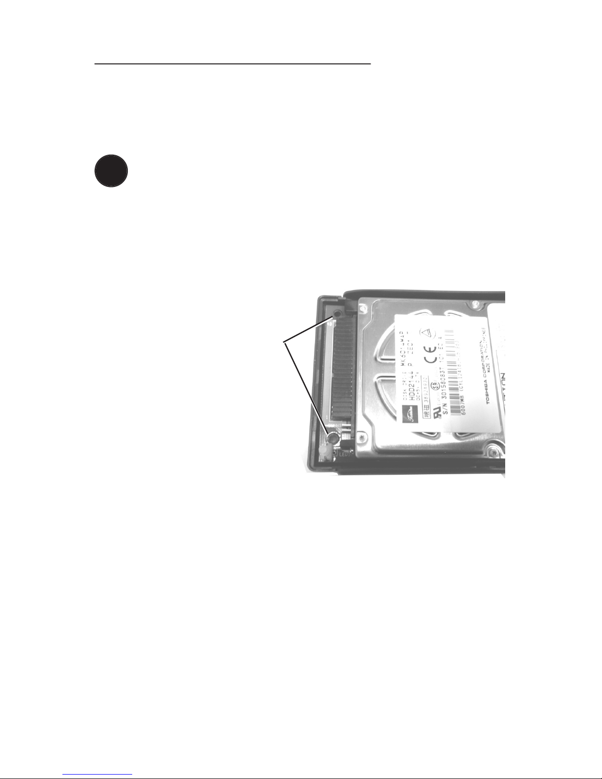
Preparing to Assemble the Transport Kit
List of Items
Your Transport Pro FireWire/USB Portable Hard Drive Kit should
include the fol low ing components:
(1)
Transport Pro FireWire/USB Hard Drive Kit enclosure
!

!
2
MCE Transport Pro Kit Installation Guide
(1) FireWire cable
(1) USB cable
(1) Hard Disk Speed Tools FireWire driver software
(1) AC adapter
(4)
4mm metric screws (inside the enclosure)
(4)
1cm tapping screws (inside the enclosure)
(1)
MCE mini combo screwdriver
Assembling the Transport Pro Kit
You will need a 2.5” IDE hard drive and a little patience to com-
plete this in stal la tion.
Caution:
Electro-Static Dis charge (ESD) can easily dam-
age elec tron ic com po nents. Be fore pro ceed ing, ensure
that you are dis charged of static electricity by touch ing a
ground ed metal object or by using the pro vid ed disposable
grounding wrist strap according to its in struc tions.
Step 1:
Place the hard drive and Kit materials on a table or other
dry, at work area. Orient the enclosure such that its ports are fac-
ing to your right.
Step 2:
If you have not
already done so, lift the top
cover of the enclosure off of
the base (they are not per ma -
nent ly attached yet) and place
it nearby. Remove the small
bag of screws from inside the
en clo sure and lay them aside.

!
Hard Drive Pins
Group B
Group A
!
MCE Transport Pro Kit Installation Guide
3
Note:
The faceplate surrounding the Trans port Proʼs
FireWire/USB ports is re mov able and may come out of its
slot. If so, simply remember to put it back before re plac ing
the en clo sureʼs top cover later.
Step 3:
Holding the en clo sure
base with your right hand,
grasp the long black connec-
tor (la beled CONN1A in small
white letters) with your left
hand and lift the left side of
the green Printed Circuit Board
(PCB) up slightly and then to the
left until it comes away from the base.
You may need to wiggle the PCB gently
to detach the FireWire/USB ports from the port faceplate.
Step 4:
Lay the enclosure base aside and gently lay the PCB in
front of you.
Caution:
In the upcoming steps, be VERY gentle with the
Transport Pro PCB. Be careful not to touch the electronic
com po nents it con tains on its underside.
Step 5:
Examine the con nec tor pins of your hard drive and no-
tice that the drive has two distinct groups of pins. The rst group
(Group A) has 2 rows of 22 con tig u ous pins (one pin in the bottom
row will be missing). The second group (Group B) con sists of 4
pins, which are sep a rat ed from the other group by a no tice able gap.

4
MCE Transport Pro Kit Installation Guide
Step 6:
Holding the drive at a slight angle,
align the Group A pins of the hard drive
with the black hard drive
con nec tor labeled
CONN1A and insert
the tips of the hard
drive pins into the con-
nec tor.
Step 7:
Once the tips of the hard drive pins are inserted, you can
lay the drive down onto the PCB. Holding the left end of the PCB
with your left hand,
care ful ly but rmly
push the hard drive to
the left with your right
thumb and index nger
to com plete ly insert the
hard drive pins into the
con nec tor.
Step 8:
Making sure that the
hard drive does not fall, turn
the PCB/hard drive as sem bly
over and secure the drive to
the PCB. Screw the four short
metric screws provided into
either the four outer screw slots or
the four inner slots, depending on the
drive installed.

MCE Transport Pro Kit Installation Guide
5
Step 9:
Be sure the FireWire/USB port faceplate is prop er ly set
into the Transport Pro enclosure base.
Note:
If you need to slip the faceplate back in, be sure that
the lip at the bottom of the face plate ts into the slotted
groove in the enclosure base. The side of the faceplate fac-
ing outward should be ush with the base.
Step 10:
Carefully lay the PCB/hard drive as sem bly (hard
drive facing up) into the Transport Pro base by rst inserting the
FireWire/USB ports
into the faceplate and
then gently lowering
the other side of the
PCB. Make sure that
the two circular slots
in the PCB on either
side of the long black
con nec tor labeled
CONN1A t per fect ly
over two posts in the
base of the Transport Pro.
Step 11:
Lower the top cover of the Transport Pro onto the enclo-
sure base, aligning the two halves for a proper t.
Step 12:
Carefully turn the entire unit over and use the four 1cm
tapping screws to secure the two en clo sure halves together. Be
careful not to over-tighten the screws.
Your Transport Pro FireWire/USB Portable Drive is now ready for
use. Please refer to the Userʼs Guide for information on op er a tion
of the drive.
!

6
MCE Transport Pro Kit Installation Guide
Troubleshooting
Troubleshooting
The power/activity LED does not light up when power is supplied
to the drive.
•
This is usually due to either the FireWire cable not being con-
nect ed properly while operating in FireWire mode, or the AC
adapter not being properly connected while operating in USB
mode. Dis con nect the rel e vant cable and re con nect it en sur ing
that it is securely seated into its con nec tor at both ends of the
cable.
The hard drive mechanism does not spin when powered by either
the FireWire bus or AC power.
•
This is usually due to either the FireWire cable not being con-
nect ed properly while operating in FireWire mode, or the AC
adapter not being properly connected while operating in USB
mode. Dis con nect the rel e vant cable and re con nect it en sur ing
that it is securely seated into its con nec tor at both ends of the
cable.
•
The hard drive may be improperly con nect ed to the PCB drive
con nec tor. Check to ensure that the drive is secured properly by
dis con nect ing it and then reconnecting to the drive connector on
the PCB, making sure that the Group B pins are NOT connected,
but are left completely exposed (Step 5 on page 3).
If you have exhausted all of the troubleshooting recommendations
outlined here and still have not resolved the problem, you may re-
ceive technical as sis tance by calling (949)458-0800 or by send ing
an email to [email protected]. Please provide the

MCE Transport Pro Kit Installation Guide
7
following information:
•
Your name
•
Invoice number
•
Date of the invoice
•
MCE part number
•
PowerBook model
•
Mac OS version number
•
Description of the problem, including any relevant error mes-
sages
Since technical assistance representatives do not have access to
invoice in for ma tion, it is necessary that you have this information
with you when contacting them.

MCE Technologies, LLC
Irvine, California, USA
Technical Support
(949)458-0800
Sales
(800)500-0622
http://www.mcetech.com
Copyright © 2001 MCE Technologies, LLC. All rights reserved.
MCE, the MCE logo, and Transport Pro are trade marks of MCE Tech-
nol o gies, LLC.
Apple, Mac, the Mac OS logo, Macintosh, PowerBook, iBook, and Drive
Set up are trademarks of Apple Computer, Inc. reg is tered in the U.S. and
other countries.
Products and company names are trademarks of their respective com-
pa nies, and are mentioned for informational purposes only and con sti tute
neither an endorsement nor a recommendation.
Every effort has been made to ensure that the information in this manual
is accurate. MCE Technologies, LLC is not re spon si ble for print ing or
clerical errors. Information in this document is sub ject to change without
notice and does not represent a com mit ment on the part of MCE Tech-
nol o gies, LLC.
Rev. 0231
Table of contents
Other MCE Technologies Storage manuals

MCE Technologies
MCE Technologies POWERBOOK G4 User manual

MCE Technologies
MCE Technologies Xcaret Pro User manual

MCE Technologies
MCE Technologies Xcaret Pro User manual

MCE Technologies
MCE Technologies OptiBay User manual

MCE Technologies
MCE Technologies Optibay series User manual

MCE Technologies
MCE Technologies Desktop Internal DVD-R/RW and CD-R/RW Drive User manual

MCE Technologies
MCE Technologies Xcaret Pro-99 User manual

MCE Technologies
MCE Technologies Xcaret Pro User manual