manuals.online logo
Brands
  1. Home
  2. •
  3. Brands
  4. •
  5. McIntosh
  6. •
  7. Amplifier
  8. •
  9. McIntosh MX 110 User manual

McIntosh MX 110 User manual

CONTENTS
GENERAL
DESCRIPTION.
1
TECHNICAL
DESCRIPTION.
1
INTRODUCTION.
3
FM
ALIGNMENT.
4
MULTIPLEX
ALIGNMENT.
6
SCHEMATIC.
8
DIAL
STRINGING.
11
PARTS
LIST.
12
SPECIFICATIONS..
16
CHASSIS
LAYOUT.
.
18
OPERATING
CURVES.
20
M
AND
X
SERIES
SCHEMATICS.POCKET
2
CHAMBERS
ST.
BINGHAMTON,
N.Y.
WARRANTY
STATION
MX
110
SERVICE
MANUAL
nWntosh
mx
MX
110
TUNER
PREAMPLIFIER
GENERAL
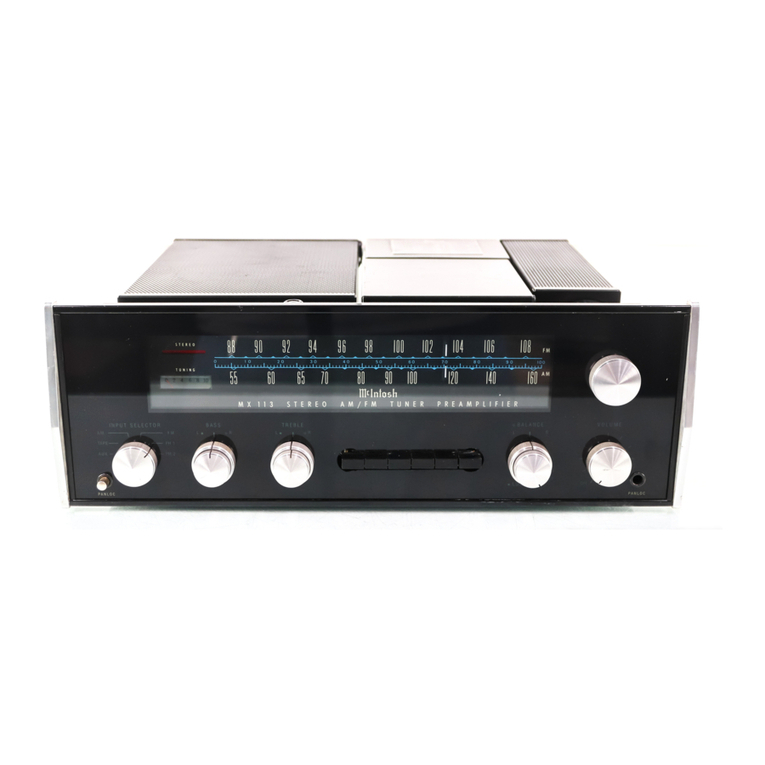
DESCRIPTION
The
MX
110
combines
in
one
unit
an
extremely
low-distortion
preamplifier
with
a
highly
sensitive
FM
multiplex
stereo
tuner.
Every
desirable
feature
of
a
tuner
and
a
preamplifier
is
included
in
this
design.
Interstation
noise
suppression,
tuning
indicator,
FM
multiplex
indicator,
indi¬
vidual
channel
bass
controls,
individual
channel
treble
controls,
electronic
phase
switch
have
all
been
engineered
into
the
MX
110.
The
INPUT
SELECTOR
gives
you
a
choice
of
six
different
program
sources.
The
MODE
SELECTOR
is
a
newly
developed
control
which
makes
it
very
easy
to
balance
a
stereo
system.
It
is
designed
to
add
left
to
right
for
monophonic
operation,
to
control
the
left
to
right
stereo
perspective
or
to
compare
the
left
and
right
channels
of
a
stereo
program.
The
loudness
of
the
phono
channels
and
the
auxiliary
channel
may
be
balanced
to
the
TECHNICAL
The
radio-frequency
amplifier
of
the
MX
110
is
a
“cascode”
type
circuit.
The
circuit
is
specially
designed
to
amplify
weak
signals
with
less
noise
and
distortion.
By
carefully
tuning
this
RF
amplifier
during
manufacturing
and
controlling
other
circuit
constants,
spurious
response
rejec¬
tion
is
improved.
The
high-frequency
oscillator
mechanical
layout
is
engineered
for
minimum
response
to
temperature
variations.
In
fact
the
combination
of
mechanical
and
electronic
design
is
so
unusually
good
in
this
circuit
that
automatic
frequency
control
is
not
needed
in
the
MX
110.
The
mixer
output
is
amplified
by
four
inter¬
mediate
frequency
amplifiers.
The
transformers
used
in
the
I.F.
amplifiers
are
designed
for
max¬
imum
adjacent
channel
rejection,
for
electrical
stability,
and
for
electrical
and
mechanical
resistance
to
shock
and
vibration.
tuner
loudness.
These
adjusting
controls
are
located
on
the
top
of
the
MX
110
behind
the
front
panel.
By
releasing
the
PANLOC
buttons
on
the
front
panel,
you
can
slide
the
MX
110
out
of
its
mounting
until
the
second
latch
en¬
gages.
The
top
mounted
LEVEL
set
controls
are
now
available.
The
McIntosh
designed
PANLOC
system
is
the
first
professional
installation
technique
to
be
used
on
stereo
instruments.
The
PANLOC
sys¬
tem
gives
you
absolute
ease
of
installation,
operation,
and
maintenance.
The
McIntosh
MX
110
is
a
beautifully
engi¬
neered
control
center
for
the
finest
stereo
sound
systems.
The
extreme
care
in
manufacturing,
in
layout
design
and
in
thermal
engineering
prom¬
ises
the
usual
McIntosh
extra
values
of
reliability,
performance,
and
long
life.
DESCRIPTION
The
R.F.
and
I.F.
circuits
of
the
MX
110
are
completely
shielded
and
exceed
the
FCC
requirements
for
suppression
of
oscillator
radia¬
tion.
Either
a
300
ohm
or
75
ohm
antenna
may
be
used
with
the
MX
110.
A
VHF
television
antenna
which
is
suitable
for
FM
reception
can
be
connected
to
the
MX
110.
In
the
MX
110,
a
new
type
of
mechanical
tuning
assembly
gives
smooth
flywheel
tuning.
By
controlling
the
relations
between
mass
and
mechanical
resistance,
and
dividing
work
loads
in
the
dial
drive
system,
it
becomes
nearly
impossi¬
ble
to
detect
any
backlash.
Yet
the
entire
dial
drive
is
a
model
of
mechanical
stability.
For
smooth,
quiet
action
and
extended
life
with
virtually'
no
wear,
a
teflon
lined
dial
pointer
carriage
and
nylon
pulleys
are
used
in
the
dial
cord
assembly.
1
MULTIPLEX
DECODER
The
multiplex
decoder
uses
a
special
McIntosh
developed
detecting
circuit.
One
of
the
advan¬
tages
of
this
circuit
is
the
elimination
of
the
critical
adjustments
necessary
with
commonly
used
matrixing
methods.
This
circuit
detects
the
L+R
sidebands
and
automatically
matrixes
the
recovered
information
with
the
L+R
main
carrier
signal.
This
circuit
then
yields
the
left
and
the
right
program
with
maximum
separation.
A
temperature
stabilized
19KC
amplifier
locks-in
a
highly
stable
push-pull
synchronous
oscillator.
Apart
from
other
advantages,
this
method
provides
greatest
noise
immunity.
Bal¬
anced
detectors
cancel
the
38KC
component
in
the
output
and
insure
low
distortion.
A
three-section
sharp
cut
off
filter
rejects
SCA
interference
and
reduces
susceptibility
to
spuri¬
ous
signals.
The
MX
110
has
an
MPX
stereo
indicator
that
lights
when
the
dial
pointer
crosses
a
station
broadcasting
MPX
stereo.
A
unique
circuit
using
a
transistor
operates
the
MPX
stereo
indicator.
The
transistor
is
controlled
by
a
differential
detecting
circuit
that
amplifies
the
19KC
pilot
signal.
This
circuit
automatically
discriminates
between
the
19KC
signal
and
noise.
AUDIO
The
MX
110
audio
amplifier
consists
of
three
negative-feedback
amplifying
sections
in
dupli¬
cate
for
the
left
and
right
stereo
channels
and
a
separate
L+R
monophonic
amplifier.
The
first
section
in
each
channel
is
a
feedback
preamplifier
used
to
amplify
and
compensate
for
the
input
signals
coming
from
phonograph
pickups
or
tape
heads.
Level
set
controls
are
connected
into
the
output
circuit
of
this
preamplifier
section
when
the
INPUT
SELECTOR
is
switched
to
PHONO
1
or
PHONO
2.
These
controls
may
be
used
to
maintain
uniform
loudness
between
phono
and
tuner
inputs.
Skillful
layout,
grounding,
and
shielding
for
low-hum
pickup,
metal
film
resistors,
low-noise
tubes
and
extreme
care
in
manufactur¬
ing
combine
to
reduce
noise
and
hum
in
t
input
amplifiers.
octave)
rumble
and
high-frequency
filters
are
associated
with
this
section.
The
third
amplifier
section
is
a
two
stage
negative
feedback
amplifier.
The
variable
bass
and
treble
controls
are
included
in
the
feedback
loop
to
maintain
the
lowest
possible
distortion.
For
example
a
wave
meter
analysis
of
the
three
amplifier
sections
of
the
MX
110
shows
less
than
1/10
of
1%
distortion
at
3
volts
output.
The
MODE
SELECTOR,
balance
controls
and
left
and
right
outputs
are
associated
with
the
third
amplifier
section.
The
L+R
monophonic
amplifying
section
is
a
feedback
summing
amplifier.
It
supplies
mono¬
phonic
output
as
well
as
L+R
output.
The
second
amplifier
section
in
each
channel
is
a
cathode
follower.
The
sharp
cut-off
(18db
per
POWER
SUPPLY
The
power
supply
of
the
MX
110
has
received
very
special
design
attention.
Two
separate
rectifier
circuits
are
used.
A
full-wave
rectifier
supplies
D.C.
to
the
heaters
of
all
audio
stages.
A
bridge
rectifier
supplies
D.C.
to
the
anodes
of
the
audio
stages.
A
half-voltage
tap
on
the
bridge
rectifier
supplies
D.C.
to
the
tuner
stages.
This
elaborate
power
supply
design
insures
the
lowest
possible
background
hum
level
and
also
the
maximum
stability.
In
addition
to
this
care¬
ful
work
the
power
transformer
uses
special
magnetic
shielding
to
minimize
possible
hum
pickup
in
the
MX
110
as
well
as
in
any
other
equipment
used
with
it.
Hi
2
INTRODUCTION
All
McIntosh
tuners
are
carefully
aligned
and
tested
at
the
factory
using
the
finest
available
test
equipment.
All
McIntosh
tuners
will
meet
their
published
specifications
when
shipped
from
the
factory.
After
extensive
operation,
especially
when
tubes
have
been
replaced,
it
may
be
desirable
to
realign
the
tuner
circuits
for
best
performance.
This
manual
gives
complete
information
on
the
circuit
realignment
procedure
for
the
MX
110
tuner-preamplifier.
The
test
equipment
listed
below
(or
its
equivalent)
is
necessary
to
properly
align
an
MX
110.
The
accuracy
of
the
alignment
will
be
directly
related
to
the
accuracy
and
calibration
of
the
test
equipment
used.
FM
Signal
Generator
(Measurements
210A
or
equivalent)
VTVM
Multiplex
Generator
(RCA
WR-51A
or
equivalent)
10.7
MC
Generator
(Preferably
crystal
controlled)
Oscilloscope
(Hewlett-Packard
120B
or
equivalent)
Harmonic
Distortion
Analyzer,
desirable
but
not
essential—(Hewlett-
Packard
330B
or
equivalent)
If
the
necessary
test
equipment
is
not
available,
alignment
should
not
be
attempted.
You
may
contact
the
McIntosh
Customer
Service
Department
for
additional
information.
Customer
Service
McIntosh
Laboratory,
Inc.
2
Chambers
Street
Binghamton,
New
York
Our
telephone
number
is
723-5491
The
direct
dial
area
code
is
607
T
MX
110
FM
STEPS
TUNER
DIAL
SETTING
SIGNAL
GENERATOR
INDICATOR
FREQ
COUPLING
MODULATION
TYPE
CONNECTED
TO
Point
of
no
interference
or
signal
10.7MC
Through
external
.01
MF
cap
to
pin
7
of
12AT7
mixer
cw
VTVM
TP
#1
SAME
SAME
SAME
SAME
MX
110
tuning
eye
SAME
SAME
SAME
SAME
VTVM
TP
#2
or
(discriminator
output
on
"M"
series)
SAME
SAME
SAME
SAME
SAME
Pin
6
of
discriminator
transformer
105MC
105MC
300
ohm
antenna
terminals
with
*
matching
network
400
cycles
75KC
deviation
(100%
modulation)
VTVM
connected
to
TP1
and
scope
connected
to
L
or
R
audio
output
90MC
90MC
SAME
SAME
SAME
105MC
105MC
SAME
SAME
SAME
90MC
90MC
SAME
SAME
SAME
Point
of
no
interference
Scope
L
or
R
output
105MC
105MC
SAME
400
cycles
75KC
deviation
(100%
modulation)
attenuated
to
2.5
microvolts
output
VTVM
connected
to
TP
#1
and
Scope
connected
to
L
or
R
audio,
output
ANTENNA
MATCHING
NETWORK
FM
SIGNAL
GENERATOR
100
OHMS
-AAA—
-O
-AAA—
150
OHMS
TUNER
300
OHM
ANTENNA
°
TERMINALS
*
IF
SIGNAL
GENERATOR
HAS
OTHER
THAN
50
OHM
INTERNAL
IMPEDANCE,
USE
A
RESISTOR
OF
150
OHMS,
LESS
INTERNAL
GENERATOR
IMPEDANCE.
1
]
ALIGNMENT
ADJUST
TEST
LIMITS
REMARKS
Top
(secondary)
and
bottom,
(primary)
of
1st,
2nd
and
3rd
IF
transformers
Maximum
possible
negative
voltage
Shunt
to
ground
the
winding
not
being
adjusted
with
a
.01
MF
capacitor
in
series
with
a
1
K
resistor.
Attenuate
signal
generator
until
output
voltage
at
TP
#1
is
less
than
1.5
volts
with
one
IF
transformer
winding
shunted.
IF
transformers
have
terminal
#1
marked
with
a
green
dot
and
are
numbered
clockwise.
4th
IF
transformer,
top
and
bottom.
Eye
should
close
to
approx,
’/is”
with
strong
signal.
Make
additional
adjustments
of
eye
closure
by
varying
the
length
of
parallel
conductors
connected
to
pins
1
and
4
of
the
4th
IF
transformer.
(This
changes
the
capacitive
coupling
between
pins
1
and
4.)
Discriminator
transformer
upper
core
(secondary)
Adjust
for
0
volts
!
-
-
Discriminator
transformer
lower
core
(primary)
Maximum
negative
voltage
Repeat
step
3
if
a
large
change
is
made
in
the
setting
of
the
lower
core.
i
Oscillator
trimmer
cap.
Maximum
negative
voltage
As
output
increases,
attenuate
signal
generator
to
keep
maximum
output
at
TP
#1
to
less
than
2
volts.
Oscillator
coil
tuning
slug
SAME
Repeat
steps
5
and
6
until
dial
calibration
is
accurate.
j
Mixer
trimmer
and
RF
trimmer
SAME
1
|
Mixer
coil
tuning
slug
and
RF
coil
tuning
slug
SAME
Repeat
steps
7
and
8
until
output
is
as
high
as
possible.
Muting
adj.
control
Turn
muting
switch
to
"in''
position.
Adjust
muting
control
until
background
noise
just
disappears.
i
IHFM
sensitivity
2.5
microvolt
for
3
%
total
noise
and
distortion
Step
10
is
an
overall
sensitivity
check,
and
requires
a
distortion
analyzer
and
i
FM
signal
generator
with
attenuator.
With
2.5
microvolts
input
at
the
300
ohm
antenna
terminals,
TP
#1
voltage
should
be
.6
volts
or
more.
MX
IIO
MULTIPLEX
TUNER
SIGNAL
GENERATOR
_
INDICATOR
STEPS
DIAL
SETTING
FREQ.
COUPLING
MODULATION
TYPE
CONNECTED
TO
i
Point
of
no
interference
or
signal
Audio
generator
set
to
67KC,
0.5
volts
output
or
less
TP
H2
(MPX
input
on
"M"
series)
Audio
VTVM
Pin
6
of
38KC
transformer
(yellow
wire
connected
at
this
pin)
2
SAME
MPX
generator
with
19KC
pilot
attenuated
to
approx.
5%
level
(5%
level
is
14
of
normal
10%
level)
1
9KC
pilot
must
be
attenuated
for
correct
alignment
SAME
SAME
Pin
3
or
8
of
12AU7
MPX
oscillator
100MC
100MC
modulated
300
ohm
antenna
1
KC
100%
SAME
Pin
1
or
2
of
by
MPX
generator,
terminals
with
19KC
pilot
at
approx.
1000
normal
output
microvolt
signal
modulation
(34KC
deviation)
modulating
left
or
right
only
38KC
transformer
4
SAME
SAME
SAME
SAME
Audio
VTVM
and
scope
L
or
R
output
jack
5
SAME
SAME
SAME
SAME
SAME
SAME
6
SAME
SAME
SAME
SAME
SAME
SAME
7
SAME
SAME
SAME
Turn
off
1
KC
audio
modulation
SAME
SAME
8
SAME
SAME
SAME
Same
as
step
3
SAME
SAME
DECODER
ALIGNMENT
ADJUST
TEST
LIMITS
REMARKS
67KC
trap
Adjust
for
minimum
voltage
1
9KC
phase
coil
and
1
9KC
transformer
1.
Disable
local
38KC
oscillator
by
placing
a
jumper
wire
across
6.8K
resistor
connected
to
pins
1
and
6
of
12AU7
MPX
oscillator.
2.
Shunt
pin
2
of
19KC
transformer
to
ground
with
.01
capacitor
in
series
with
1
K
resistor.
3.
Adjust
19KC
phase
coil
for
maximum
output.
Proper
adjustment
places
core
approx.
%"
from
bottom
of
coil
form.
4.
Adjust
lower
core
of
19KC
transformer
for
maximum
output.
5.
Shunt
pin
3
of
19KC
transformer
to
ground
with
.01
capacitor
in
series
with
1
K
resistor.
6.
Adjust
upper
core
of
19KC
transformer
for
maximum
output.
7.
Remove
jumper
used
in
step
1
above.
38KC
transformer
bottom
core
Adjust
for
maximum
voltage
38KC
transformer
upper
core
Adjust
for
stable
scope
display
1.
Turn
off
19KC
pilot
on
MPX
generator.
2.
Adjust
upper
core
of
38KC
transformer
to
obtain
a
stable
and
uniform
1
KC
signal
scope
display.
This
adjustment
may
be
critical,
so
turn
core
very
slowly.
3.
Turn
19KC
pilot
back
on.
19KC
phase
coil
30db
separation
or
more
Modulate
left
channel
and
measure
right
channel
output.
Adjust
19KC
phase
coil
for
minimum
right
channel
output
(maximum
separation).
Remove
all
test
leads
from
TP
#2
for
separation
checks.
SAME
Modulate
right
channel
and
measure
left
channel
output.
Separation
in
steps
5
and
6
should
be
at
least
30db
This
step
checks
the
rejection
of
19KC
and
38KC
frequencies.
Residual
output
should
be
at
least
40db
below
modulated
output.
1
'
'
.
Check
for
MPX
indicator
light
1.
MPX
light
should
turn
on
with
MPX
signal
2.
Tuning
slowly
across
dial,
MPX
light
should
turn
on
only
with
MPX
signal.
ALL
SWITCHES
SHOWN
IN
CCW
POSITION
STEREO
INPUT
SELECTOR
SWITCH,S2
MODE
SELECTOR
SWITCH.
S3
ALL
VOLTAGES
MEASURED
UNDER
FOLLOWING
CONDITIONS:
UNLESS
OTHERWISE
SPECIFIED
I
-USE
OF
II
MEGOHMS
INPUT
IMPEDANCE
VTVM
VOLTMETER.
ALL
RESISTORS
1/2
W
20%
2
-
ALL
VOLTAGES
±10%,WITH
RESPECT
TO
GROUND.
ALL
CAPACITORS
IN
PF
3-A.C.
INPUT
AT
MTV
50
-
60
CPS.
ALL
INDUCTORS
IN
MICRON
4-NO
SIGNAL
AT
ANTENNA
AND
OTHER
INPUT
TERMINALS
5
-
FRONT
PANEL
CONTROLS
AT
FMIFHOTMC
MODE
SELECTOR
-STEREO
MUTING
-OUT
INPUT
SELECTOR
-
yPX
lF/HF
FILTERS
-
OUT
VOLUME
CONTROL
-MAX
LOUD
-OUT
BALANCE
CONTROL-ZERO
TAPE
MONITOR-OUT
TONE
CONTROLS
-FLAT
PHASE
-
0
#
MX
110
PARTS
LIST
TUBES
ITEM
NO.
USE
IDENTIFICATION
NUMBER
VI
RF
Amplifier
1
6DS4
V2
RF
Amplifier
2;
Mixer
12AT7
V3
Oscillator
6AB4
V4
IF
Amplifier
1
6AU6
V5
IF
Amplifier
2
6AU6
V6
IF
Amplifier
3;
Limiter
1
6AU6
V7
Limiter
2
6CS6
V8
Muting;
L+R
Amplifier
12AT7
V9
Tuning
Indicator
6HU6/EM87
(X,
Z
series)
6FG6
(EM84A)
M
series
VI0
FM
Audio
(Left
and
Right);
1st
Audio
Amplifier
6D10
VII
MPX.
Amplifier
and
19KC
Separator/Indicator
control
6U8
VI2
MPX.
38KC
Oscillator
12AU7
VI3
Phono
Preamplifier
Left
12AX7
VI4
Phono
Preamplifier
Right
12AX7
VI5
Left
and
Right
2nd
Audio
Amplifier
12AX7
VI6
Left
3rd
Audio
Amplifier
6U8
VI7
Right
3rd
Audio
Amplifier
6U8
TRANSISTOR
Q1
Transistor
(Switching)
Motorola
#MA-113
DIODES
D1
AGO
Clamp
Type
1
N542
Germanium
Diode
D2
Muting
and
Tuning
Eye
Detector
Type
1
N542
Germanium
Diode
D3,
D4
Discriminator
(Matched
Pair)
Type
1
N542
Germanium
Diode
D5,
D6
Balanced
Detector
(Matched
Pair)
for
Indicator
Type
1
N542
Germanium
Diode
D7,
D8
Balanced
MPX.
(Matched
Pair)
Detectors
(Left
Channel)
Type
1N542
Germanium
Diode
D9,
DIO
Balanced
MPX.
(Matched
Pair)
Detectors
(Right
Channel)
Type
1
N542
Germanium
Diode
Dll,
D12,
D13,
D14
High
and
Low
Voltage
Supply
G.E.
H6RS20PH6RGD1
D15,
D16
DC
Filament
Supply
#1N1217
12
MX
IIO
PARTS
LIST
(Cont.)
ITEM
NO.
FUNCTION
CONTROLS
RESISTANCE
IDENTIFICATION
NUMBER
R1
Muting
Adj.
Pot.
500
K
R142-217
R2
Aux.
Set
Level
(Left)
200K
R142-144
R3
Aux.
Set
Level
(Right)
200
K
R142-144
R4
Phono
1
Set
Level
(Left)
200
K
R142-144
R5
Phono
2
Set
Level
(Right)
200K
R142-144
R6
Phono
2
Set
Level
(Left)
200
K
R142-144
R7
Phono
1
Set
Level
(Right)
200K
R142-144
R8
Bass
Control
1M
(dual)
R142-142
R9
Treble
Control
500K
(dual)
R142-141
RIO
Balance
Control
68K
(dual)
with
switch
R142-109
R11
Volume
Control
40K
(dual)
R142-110B
ITEM
NO.
FUNCTION
SWITCHES
DESCRIPTION
IDENTIFICATION
NUMBER
SI
Muting
SPST
Stackpole
tfSS-26
S2
Input
Selector
6
position
rotary
S142-108A
S3
Mode
Selector
7
position
rotary
S142-147A
S4
Tape
Monitor
DPDT
Stackpole
flSS-50
S5
LF
Filter
DPDT
Stackpole
ftSS-50
S6
HF
Filter
DPDT
Stackpole
HSS-50
S7
Phase
Reverse
SPDT
Stackpole
ftSS-26-1
S8
Loudness
DPDT
Stackpole
//SS-50
S9
On-Off
(Part
of
R10)
S10
Panel
Light
Dim—Bright
SPST
Stackpole
flSS-26
ITEM
NO.
FUNCTION
TRANSFORMERS
IDENTIFICATION
NUMBER
T1
FM
first
IF
T107-134A
T2
FM
second
IF
T107-1
33A
T3
FM
third
IF
T107-133A
T4
FM
fourth
IF
T124-136A
T5
FM
discriminator
T107-135B
T6
19KC
amplifier
T129-101
T7
38KC
oscillator
T129-102A
T8
Baiun
T9
Power
T124-127B
13
MX
IIO
PARTS
LIST
(Cont.)
CAPACITORS
ITEM
NO.
DESCRIPTION
CAPACITANCE
VOLTAGE
TOLERANCE
IDENTIFICATION
NUMBER
Cl
C2
C3
C4
C6
C8
Variable
FM
Antenna
Trimmer
Mixer
Trimmer
Oscillator
Trimmer
ceramic
feed
thru
ceramic
feed
thru
1
-8pf
1
-8pf
.001
.001
C142-130A
Part
of
C-1
C9
ceramic
tubular
5pf
±.25pfN330
CIO
ceramic
tubular
5pf
±.25pfN330
C11
ceramic
feed
thru
.001
Cl
2
ceramic
tubular
5pf
±.25pfN220
Cl
3
ceramic
tubular
5pf
±.25pfN330
Cl
5
ceramic
tubular
1.5pf
±.25pfNPO
Cl
6
ceramic
disc
20%
N470
Cl
7
ceramic
tubular
3pf
+
.25NPO
Cl
8
ceramic
feed
thru
.001
mf
Cl
9
phenolic
,39pf
10%
C24
ceramic
feed
thru
.001
C28
phenolic
.18pf
10%
C31
ceramic
feed
thru
.001
C33
ceramic
feed
thru
.001
C34
ceramic
tubular
15pf
±.75pfN150
C38
ceramic
tubular
lOpf
NPO
C39
ceramic
feed
thru
.001
C44
ceramic
feed
thru
.001
ceramic
disc
47pf
C48
ceramic
feed
thru
lOOpf
C49
ceramic
feed
thru
.001
C53
silver
mica
10OOpf
10Ov
5%
C55
ceramic
disc
lOOpf
10%N1500
C59
silver
mica
1200pf
lOOv
5%
C60
silver
mica
2700pf
10Ov
5%
C61
silver
mica
1200pf
lOOv
5%
C70
silver
mica
4700pf
lOOv
5%
C73
silver
mica
10OOpf
lOOv
5%
C75
silver
mica
10OOpf
10Ov
5%
C79
ceramic
disc
39pf
20%N1
500
C80
ceramic
disc
39pf
20
%N
1500
C83
ceramic
tubular
430pf
±5%
C84
ceramic
tubular
430pf
±5%
Cl
13
ceramic
disc
2x
.01
mf
1400v
Cl
14
electrolytic
10mf
450v
Cl
15
electrolytic
40,40,
20,30
300,200,350,200
Cl
26
electrolytic
12mf
250v
Cl
17
electrolytic
1000,
2000
15v
Cl
18
ceramic
feed
thru
.001
Cl
19
ceramic
feed
thru
.001
Cl
20
ceramic
feed
thru
.001
Cl
16
electrolytic
50,50,
50,
50
200v
Cl
24
silver
mica
4700
10Ov
5%
14
MX
110
PARTS
LIST
(Cont.)
COILS
ITEM
NO.
DESCRIPTION
VALUE
IDENTIFICATION
NUMBER
LI
Antenna
Coil
LI
24-227
L2
Mixer
Coil
LI
24-247
L3
Oscillator
Coil
LI07-206A
L4
Peaking
coil:
19KC
trap
LI
29-103
L5
Filter
coil:
67KC
trap
L129-110
L6
RF
choke
.47
micro
H.
L7
RF
choke
2.2
micro
H.
L8
RF
choke
1.2
micro
H.
L9
RF
choke
SP10,
004
LI
0
RF
choke
1.2
micro
H.
L11
RF
choke
75
micro
H.
LI
2
RF
choke
38
micro
H.
LI
29-123
LI
3
Filter
coil
LI
29-109
LI
4
Filter
coil
LI
29-109
LI
5
RF
choke
2.2
micro
H.
LI
6
RF
choke
2.2
micro
H.
LI
7
RF
choke
1.2
micro
H.
LI
8
RF
choke
1.2
micro
H.
LI
9
RF
choke
1.2
micro
H.
ITEM
NO.
SPECIAL
RESISTORS
DESCRIPTION
VALUE
TOLERANCE
WATTAGE
R102
metallic
film
330K
5%
1
R103
metallic
film
330K
5%
1
R104
metallic
film
330K
5%
1
R105
metallic
film
330K
5%
1
R96
metallic
film
1,8K
5%
Vz
R97
metallic
film
1.8K
5%
%
\
MISCELLANEOUS
Lamp,
festoon:
7
volts,
2
watts,
6
x
43mm
Lamp,
Incandescent:
No.
1850
(for
MPX.
indicator
light)
Plate,
printed
circuit
for
tone
control:
No.
PC
124-113
Plate,
printed
circuit
for
LF
Filter:
No.
PC
124-112
Plate,
printed
circuit
for
HF
Filter:
No.
PC
124-1
65
Cable,
coaxial:
50
ohms,
Amphenol
No.
21
-598
15
MECHANICAL
SPECIFICATIONS
DIMENSIONS
Chassis:
16
inches
wide;
5
7
/,
6
inches
high;
13
inches
deep
including
connectors.
Front
Panel:
16
inches
wide;
5
7
/i«
inches
high.
Knob
Clearance:
1
%
inches.
FINISH
Anodized
gold
and
black
(front
panel).
INSTALLATION
Convenient,
professional
PANLOC.
WEIGHT
Chassis:
27
%
pounds.
Shipping
Weight:
36
pounds.
TUNER
SPECIFICATIONS
SENSITIVITY
Better
than
2.5
microvolts
at
100%
modulation.
R.F.
AMPLIFIER
Cascode.
I.F.
AMPLIFIERS
Four.
LIMITERS
Two.
I.F.
BANDWIDTH
200KC
flat
top.
I.F.
TRANSFORMERS
Mechanically
captive.
MUTING
I.F.
injected.
TUNING
INDICATOR
Tuning
is
indicated
by
an
electron
ray
tube.
FREQUENCY
RESPONSE
Within
+1db
20
to
20,000
cycles.
(Including
75
microseconds
deemphasis.)
HUM
Greater
than
70db
or
more
below
100%
mod.
(Audio
tubes
have
D.C.
on
the
filaments.)
DRIFT
Less
than
25KC.
ANT.
INPUT
IMPEDANCE
300
balanced,
75
ohms
unbalanced.
RADIATION
Substantially
below
F.C.C.
requirements.
DISTORTION
Less
than
0.6%
distortion
at
100%
modulation,
+
75KC
deviation
above
2.5
microvolts
at
antenna.
MULTIPLEX
DECODER
SPECIFICATIONS
MPX
DECODER
Hum
Level:
Better
than
60db
below
100%
stereo
modulation.
Distortion:
Less
than
0.3%
(Multiplex
Decoder
only).
Channel
Separation:
Better
than
30db
at
1000
cps.
Suppression
of
Pilot
(19KC),
and
Carrier
(38KC):
Greater
than
40db
below
100%
modulation.
Front
Panel
Stereo
Indicator
Light:
Activated
by
19KC
pilot
carrier
only.
INPUTS
Total
5
each
channel:
AUX.;
PHONO
1
MAG.
or
XTAL;
PHONO
2
MAG.;
TAPE
HEAD;
TAPE
MONITOR.
AUDIO
SPECIFICATIONS
OUTPUTS
Main
Stereo
Outputs;
1
Tape
Stereo
Output;
1
L+R
Output.
AC
AUX
OUTLETS
1
unswitched,
2
switched.
16
CONTROLS
Input
Selector:
Total
6
positions:
AUX,
MPX,
FM,
PHONO
1,
PHONO
2,
TAPE
HEADS.
Mode
Selector:
Total
7
positions:
LTO
L&R,
R
TO
L&R,
STEREO
REV.,
STEREO,
MONO,
L
+
R
TO
L,
L+R
TO
R.
Tone:
Dual
treble
and
bass
negative-feedback
con¬
trols
with
slip
clutch
for
independent
adjustment
of
each
channel.
Bass
Boost:
15db
at
50
cycles.
Bass
Cut:
18db
at
50
cycles.
Treble
Boost:
15db
at
10,000
cycles.
Treble
Cut:
15db
at
10,000
cycles.
Balance:
Turn
to
right
to
emphasize
the
right
chan¬
nel.
Turn
to
the
left
to
emphasize
the
left
channel.
Phase:
2
positions:
NORMAL
or
REVERSED:
Changing
phase
does
not
increase
distortion.
H.F.
Cutoff
Filter:
2
positions:
Flat,
or
5KC
cutoff.
(20db
per
octave.)
L.F.
Cutoff
Filter:
2
positions:
Flat,
or
50
cycles
cutoff.
(20db
per
octave.)
Loudness:
Fletcher
Munson
compensation.
Tape
Monitor:
2
positions:
IN
and
OUT.
For
com¬
parison
of
recorded
tape
with
program
source
after
recording.
Tuning:
Flywheel
tuning—no
backlash.
Muting:
2
positions:
IN
or
OUT
for
interstation
noise
suppression.
Level
Set:
Three
left
and
three
right
controls.
2
for
AUX,
2
for
PHONO
1,
and
2
for
PHONO
2.
These
controls
are
located
back
of
the
front
panel
on
the
top
of
the
MX
110.
AC
Power—Concentric
with
BALANCE
control:
ON-OFF.
AUDIO
ELECTRICAL
SPECIFICATIONS
FREQUENCY
RESPONSE
+
'4-db
20
to
20,000
cycles.
DISTORTION
Less
than
0.2%
at
rated
output.
HUM
AND
NOISE
High-level
inputs:
80dg
below
rated
output.
Low-
level
inputs:
less
than
3
microvolts
at
input
terminals.
INPUT
SENSITIVITY
AUX:
0.3
volt
at
200K.
PHONO
1:
3
millivolts
at
47K.
PHONO
2:
3
millivolts
at
47K.
TAPE
HEAD:
3
millivolts
at
220K.
TAPE
MONITOR:
0.3
volt
at
100K.
OUTPUTS
MAIN:
3
volts
each
channel.
L+R:
3
volts.
TAPE:
From
FM
0.9
volt.
PHONO
is
0.9
volt
for
9
millivolts
cartridge.
POWER
REQUIREMENTS:
105-125
volts
AC
50/60
cycles;
75
watts.
FUSE:
1
amp.
Slo-Blo.
TUBE
COMPLEMENT
1
6DS4
R.F.-1
amplifier
(nuvistor)
1
12AT7
R.F.-2
Mixer
1
6AB4
Oscillator
1
6AU6
IF-1
1
6AU6
IF-2
1
6AU6
IF-3/Limiter
1
1
6CS6
IF-4/Limiter
2
1
12AT7
Muting/L+R
Amplifier
1
6HU6/EM87
Tuning
Indicator
1
6D10
FM
AUDIO/Left
and
Right
1st
Audio
Amplifier
1
6U8
MPX
Amplifier
and
19KC
Separator/Indicator
control
1
12AU7
MPX
38KC
Oscillator
1
12AX7
Phono
Preamplifier
Left
1
12AX7
Phono
Preamplifier
Right
1
12AX7
Left
and
Right
2nd
Audio
Amplifier
1
6U8
Left
3rd
Audio
Amplifier
1
6U8
Right
3rd
Audio
Amplifier
2
Diodes
Discriminator
1
Diode
Muting
and
Tuning
Eye
Detectors
1
Diode
AGC
Clamp
4
Diodes
Balanced
MPX
Detectors
2
Diodes
Balanced
Det.
for
Indicator
Light
17
.
.vT
*
'
hkkiihe*
nicoofR
ijJTTT
*••*
irarm
31s
k
1
Ik-
m
iTTiJ
Tin!
Wm
m
■
Till
ijy

Other manuals for MX 110

3

Other McIntosh Amplifier manuals

McIntosh C200 User manual

McIntosh

McIntosh C200 User manual

McIntosh CR12 User manual

McIntosh

McIntosh CR12 User manual

McIntosh MA12000 User manual

McIntosh

McIntosh MA12000 User manual

McIntosh MX 117 User manual

McIntosh

McIntosh MX 117 User manual

McIntosh MCC404 User manual

McIntosh

McIntosh MCC404 User manual

McIntosh MA6200 User manual

McIntosh

McIntosh MA6200 User manual

McIntosh MA5200 User manual

McIntosh

McIntosh MA5200 User manual

McIntosh MA9500 User manual

McIntosh

McIntosh MA9500 User manual

McIntosh C22CE User manual

McIntosh

McIntosh C22CE User manual

McIntosh C26 Operating and installation instructions

McIntosh

McIntosh C26 Operating and installation instructions

McIntosh MA8900 User manual

McIntosh

McIntosh MA8900 User manual

McIntosh MA 6100 User manual

McIntosh

McIntosh MA 6100 User manual

McIntosh MC257 User manual

McIntosh

McIntosh MC257 User manual

McIntosh Power Amplifier MC303 User manual

McIntosh

McIntosh Power Amplifier MC303 User manual

McIntosh C12000 Controller User manual

McIntosh

McIntosh C12000 Controller User manual

McIntosh MHA100 User manual

McIntosh

McIntosh MHA100 User manual

McIntosh C2300 User manual

McIntosh

McIntosh C2300 User manual

McIntosh MX135 User manual

McIntosh

McIntosh MX135 User manual

McIntosh MC75 User manual

McIntosh

McIntosh MC75 User manual

McIntosh MC352 User manual

McIntosh

McIntosh MC352 User manual

McIntosh MC275 50th Anniversary User manual

McIntosh

McIntosh MC275 50th Anniversary User manual

McIntosh C11 - SERVICE User manual

McIntosh

McIntosh C11 - SERVICE User manual

McIntosh C47 User manual

McIntosh

McIntosh C47 User manual

McIntosh C53 Instruction manual

McIntosh

McIntosh C53 Instruction manual

Popular Amplifier manuals by other brands

Cambridge Audio Azur 840W Code List

Cambridge Audio

Cambridge Audio Azur 840W Code List

Mystère pa21 user manual

Mystère

Mystère pa21 user manual

Fenton 103.148 instruction manual

Fenton

Fenton 103.148 instruction manual

Tascam AV-452 Specifications

Tascam

Tascam AV-452 Specifications

Viking PA-60 product manual

Viking

Viking PA-60 product manual

Audio Authority 1392 user manual

Audio Authority

Audio Authority 1392 user manual

IOTAVX SA 3 instruction manual

IOTAVX

IOTAVX SA 3 instruction manual

Hama Scorpion manual

Hama

Hama Scorpion manual

Yamaha CA-2010 owner's manual

Yamaha

Yamaha CA-2010 owner's manual

JL Audio XD200 owner's manual

JL Audio

JL Audio XD200 owner's manual

Peavey Combo 300 owner's manual

Peavey

Peavey Combo 300 owner's manual

Kramer VM-2N user manual

Kramer

Kramer VM-2N user manual

Focusrite Green Range manual

Focusrite

Focusrite Green Range manual

Korg MMA130 owner's manual

Korg

Korg MMA130 owner's manual

Premier RD-4951USDR instruction manual

Premier

Premier RD-4951USDR instruction manual

Hubbell GAI-TRONICS SP2 manual

Hubbell

Hubbell GAI-TRONICS SP2 manual

Simlatus SoundPals DA-14 manual

Simlatus

Simlatus SoundPals DA-14 manual

Kramer VM-30AV user manual

Kramer

Kramer VM-30AV user manual

manuals.online logo
manuals.online logoBrands
  • About & Mission
  • Contact us
  • Privacy Policy
  • Terms and Conditions

Copyright 2025 Manuals.Online. All Rights Reserved.