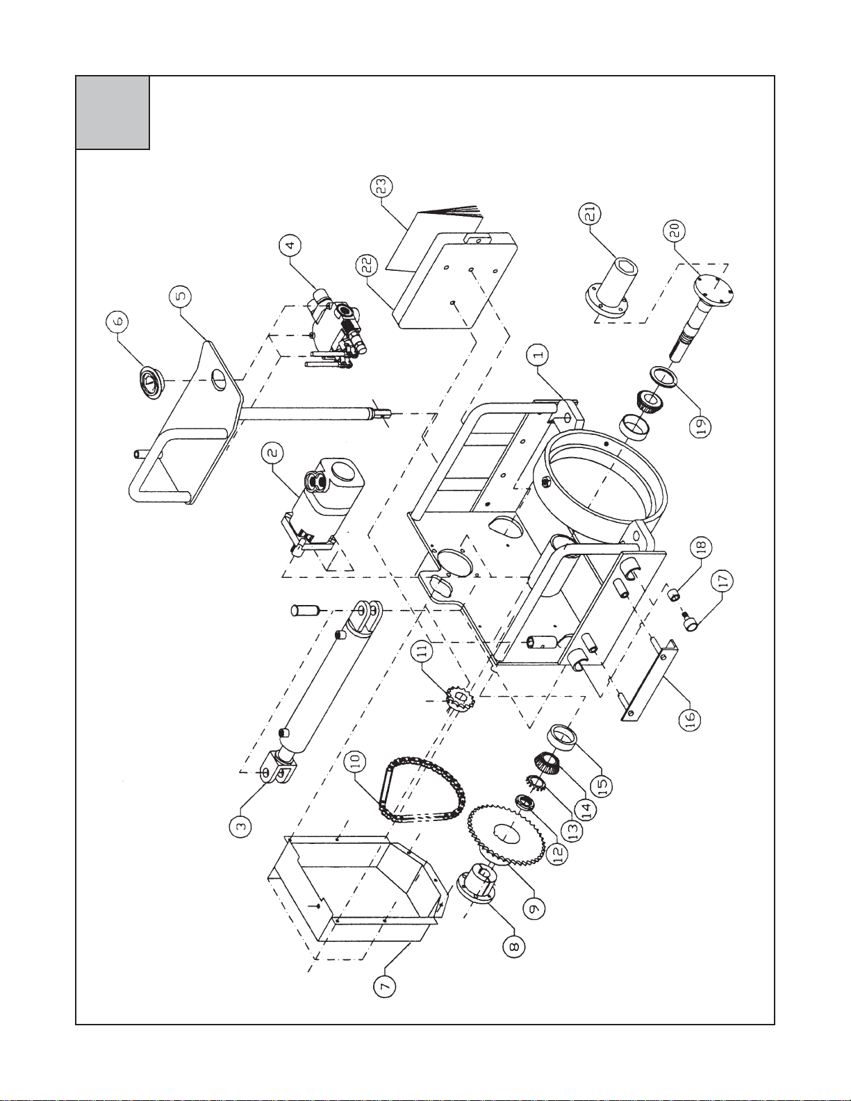
McLaughlin McL-12HB ZIPPER Operating instructions

COMPONENTS AND
REPAIR MANUAL
For Machine Serial No.
12HB - - - - 500
And Higher
MODEL McL-12HB ZIPPER
EARTH BORING MACHINE
PART NO. HD00000
Machine Serial #___________________________
Purchased &
Serviced Thru:
_________________________________________________________________________
Purchase Date: ___________________________
TABLE OF CONTENTS
Specs & Maintenance........................................................................................Section 1
Operation & Safety Manual / Hazard Alert Decal Placement...............................Section 2
Carriage Assembly.............................................................................................Section 3
Dog Plate Assembly...........................................................................................Section 4
Master Track Assembly.....................................................................................Section 5
Hoses & Fittings................................................................................................Section 6
Hydraulic Controls and Components..................................................................Section 7
Repair Instructions.............................................................................................Section 8
Warranty Statement & Return Goods Policy.......................................................Section 8
© 1990 by McLaughlin Group, Inc., reprinted 2000
Allrightsreserved. Nopartofthismanualmaybereproducedinanyformorbyany
means without prior permission of McLaughlin Group, Inc.
RR
RR
Ree
ee
epair Manpair Man
pair Manpair Man
pair Manual Pual P
ual Pual P
ual Parar
arar
art Not No
t Not No
t No.:.:
.:.:
.:
E250079E250079
E250079E250079
E250079
RevisionDate:04.03

SPECS&MAINTENANCE
McL-12HB ZIPPER
SPECIFICATIONS OF McL-12HB
EARTH BORING MACHINE
Tunnel Diameter
Free or Cased Bore 3”-12” (8-30 cm)
Chain Final Drive
Hex Size 13/16” (2.06 cm)
(customer to specify) 1-1/8” (2.85 cm)
1-3/8” (3.50 cm)
1-5/8” (4.12 cm)
Dimensions
Carriage and Pusher
Centerline Height 9-1/2” (24.1 cm)
Width 26” (66.0 cm)
Height 44” (111.8 cm)
Weight (Less Dog Plate) 320 lbs. (145 kg)
Weight (Dog Plate) 40 lbs. (18 kg)
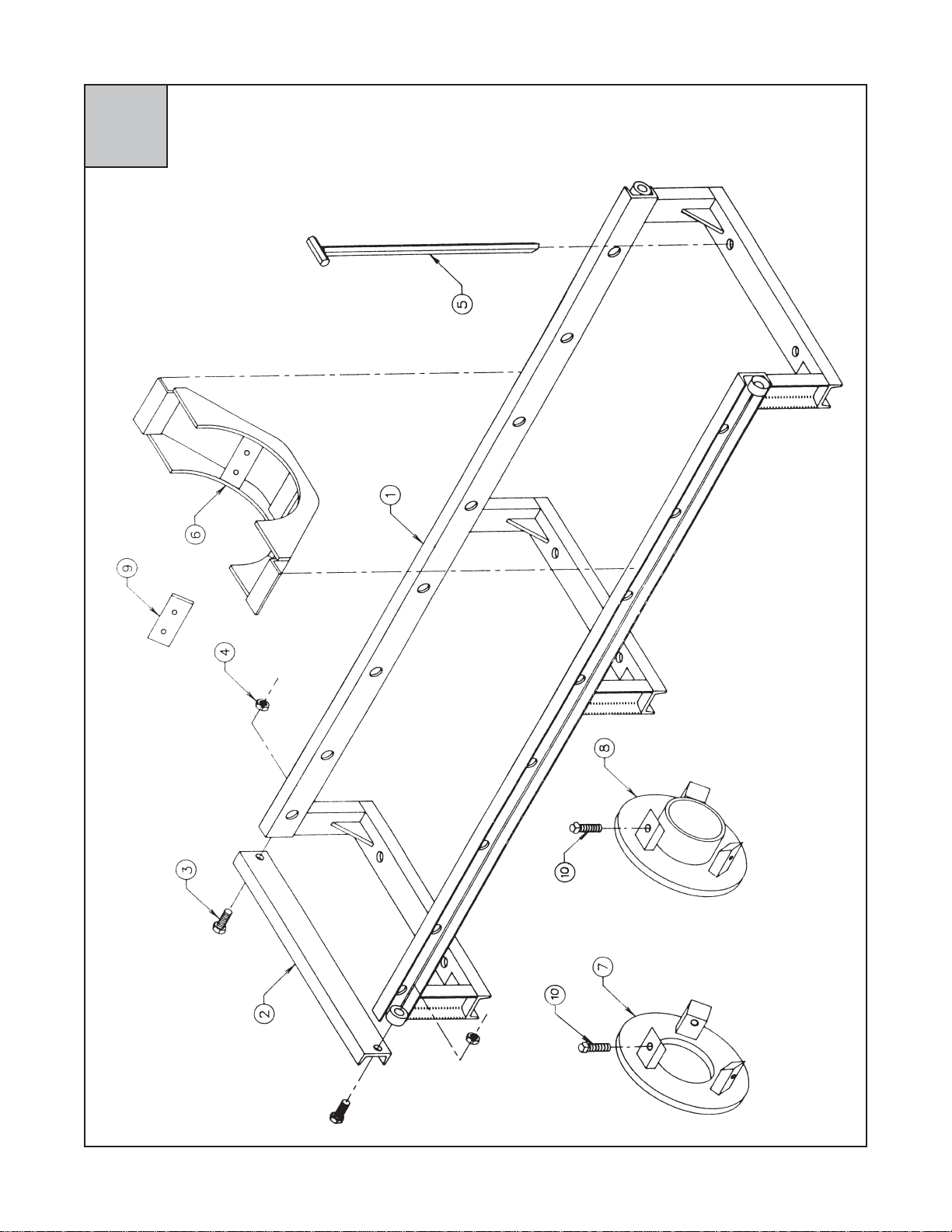
Master Track
For 4’Augers
Length 7’ (213 cm)
For 3’Augers
Length 6’ (183 cm)
Weight 85 lbs. (39 kg)
Extension Track
Length 6’ (183 cm)
Weight 75 lbs. (34 kg)
Performance
Advance Thrust
@ 2500 PSI 24,500 lbs. (109 kN)
Drive Chuck Speed
@ 20 GPM (Forward & Reverse) 120 RPM
Drive Chuck Torque
@ 2500 PSI
(Forward & Reverse) 1030 ft.* lbs. (1340 Nm)
Quick Disconnects
Parker NS-752-12FP and NS-751-12FP
Female disconnect ON MACHINE is the high pressure
side of system.
Specifications are subject to change without notice. All
weights and dimensions given are approximate. Exact
measurements should be verified if required.
MAINTENANCE INSTRUCTIONS
Review the Engine and Operation Manuals supplied
with the power source before starting and operating the
machine. Follow manufacturers recommendations for
operation and maintenance to maintain your engine
warranty.
REPAIRAND MAINTENANCE/GENERAL
Carriage/Tightness of Nuts & Bolts
Check four (4) bolts that mount chuck to the drive shaft
flange of the McL-12HB initially, then check each week
when in continuous use. Each bolt should have lock
washer. Tighten as needed.
Check four (4) bolts that mount hydraulic motor to the
McL-12HB carriage initially, then check each week
when in continuous use. Tighten as needed.
Check nine (9) bolts that hold sprocket cover to the
back of the McL-12HB initially, then once each month
when in continuous use. Tighten as needed.
Check all hydraulic fittings initially, then check each
week when in continuous use. Tighten as needed,
taking care not to twist hoses from original positions.
Check nuts (4) on cam rollers initially, then once each
month when in continuous use. Tighten as needed.
Carriage/Lubrication
Approximately every 50 hours of operation, lubricate
the chain drive of the McL-12HB. To do so, use the
grease fitting on the top of the chain guard. Use about
5-10 pumps with spindle rotating slowly. Do not over
lubricate the chain. Also, periodically grease the cam
rollers with all purpose bearing grease.
Carriage/Quick Disconnects
Wipe each Quick Disconnect with a clean rag to
remove excess oil and dirt. Always return covers to
Quick Disconnects when machine is not in use.
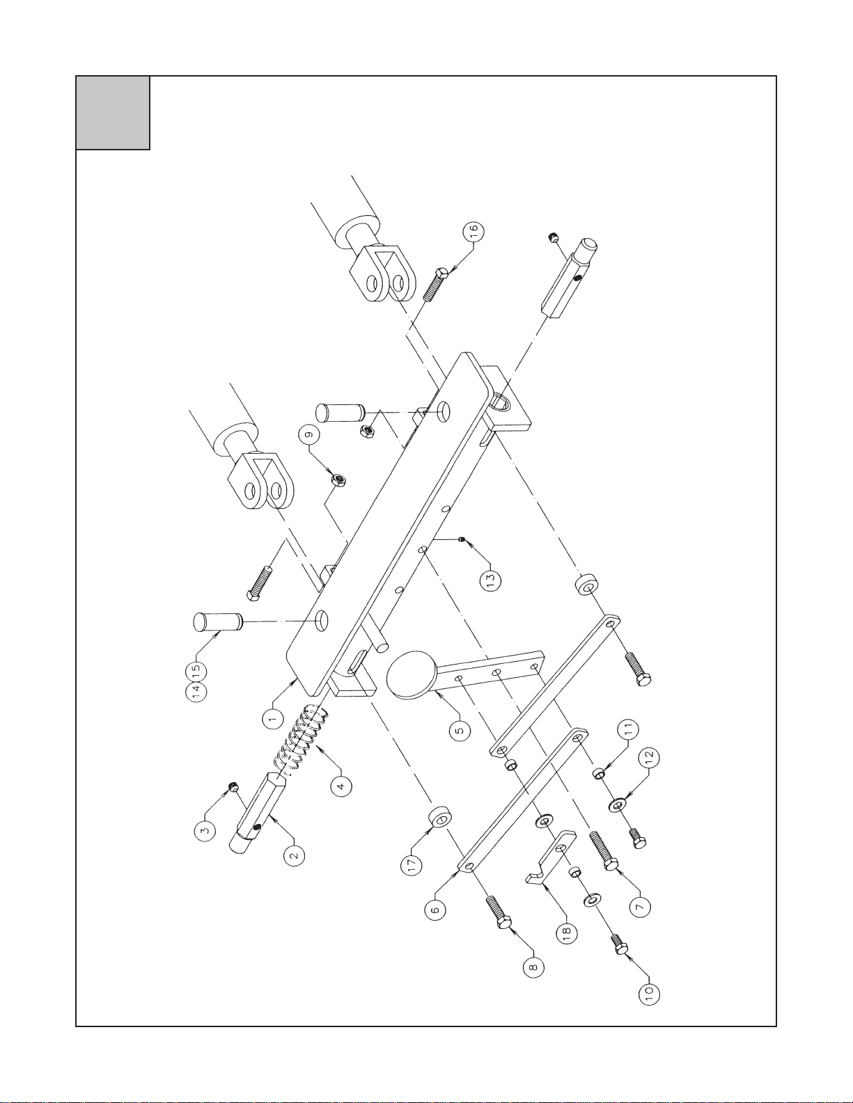
Carriage/Miscellaneous
Once a month, inspect the two (2) hitch pins (also
called Auger Pins, R-Clips, R-Pins) that hold the clevis
pins in place. Replace if worn or damaged.
Also, check hitch pins that hold machine hold downs in
place. Replace if worn or damaged.
After each boring operation is completed, clean the
carriage to remove dirt and mud. Use water if avail-
able. Always clean the unit before storage.
1.1.0

Dog Plate/General Maintenance
Check all bolts on the dog plate initially, then once a
week during continuous operation. Tighten as needed.
When tightening bolts, test dog plate to ensure proper
function.
Lubricate all members of the dog plate, including the
dog pins, initially, then each week during continuous
use. A light machine oil or spray lubricant is recom-
mended. It is also recommended that the dog plate be
removed and cleaned periodically, especially after use
in sticky clay conditions.
Before each boring operation, adjust cylinders using
the following steps: with the machine on the track, fully
extend the cylinders. Make sure the dog pins are
secure in their respective holes. Shut off power source
before working on the machine. Loosen the nuts that
lock the two set screws at the front of the dog plate.
Tighten each of these set screws until the dog plate is
held in place with no movement. Tighten the nuts to
lock the set screws. Remove all tools and personnel
from the area around the dog plate, restart the power
source and test the dog plate. Readjust if necessary.
Track/General Maintenance
Check the rolling surfaces of the track for dirt or
contamination. Clean as required.
Tighten push plate bolts periodically. Always inspect
bolts before boring begins.
Inspect the track for fractures and reweld as necessary.
Auger/General Maintenance
Apply 30W-40W oil to both shank & socket of auger
during the boring operation.
Clean and coat couplings with light oil after every use.
Examine auger after use for fractures and reweld as
necessary.
Cutting Heads/General Maintenance
Examine all teeth and replace as necessary before
use. Check all conical bits on rock heads for rotary
freedom.
Decal Identification Kit: J100110
1.2.0
SPECS&MAINTENANCE
McL-12HB ZIPPER

OPERATION&SAFETYMANUAL
McL-12HB ZIPPER
Operation and Safety Manual
E250076
2.1.0
Call 1-800-435-9340
for a replacement
Operation and Safety Manual.
Free of Charge.

McL-12HB ZIPPER
J000200 J000100
J000080
J000210
J000020
J800030 J000160
DECAL SAFETY KIT
PART NUMBER: E250600
2.2.0
HAZARDALERTDECALPLACEMENT

CARRIAGE ASSEMBLY
McL-12HB ZIPPER
3.1.0

CARRIAGE ASSEMBLY
McL-12HB ZIPPER
3.1.0
#METI.YTQREBMUNNOITPIRCSED
11 10001DHylbmessAegairraC
21 080002TciluardyH,rotoM
4020070UX31-005.CH,wercS 05.1
4001012U005.,kcoL,rehsaW
31 01603DHcilu
ardyH,rednilyC
41 09503DHciluardyH,evlaV
3022000UX81-313.CH,wercS 52.1
4040002U313.,talF,rehsaW
4501021U81-313.,kcoL
,tuN
51 05003DHgnitnuoMevlaV ylbmessA
1064000UX61-573.CH,wercS 05.1
1060001U61-573.,xeH,tuN
61 29000MHciluardyH,eguaG er
usserP
6005030UX04-5DHR,wercS 00.1
6300012U04-5kcoL,rehsaW
6300001U04-5xeH,tuN
71 52021DHdrauGtekcorpS
8081000UX81-313.
CH,wercS57.
8040012U313.talF,rehsaW
1020005T521.,gnittiFesaerG TPNM
1060504T05.,gulP,gnittiF TPNM
1relaeSenociliS
81 5
220808gnihsuBkcoLrepaT
3005000U0.2X81-573.,wercS
3060012U573.,kcoL,rehsaW
1030042UX61-8/3,teS,wercS05.
91 4220808,ht
ooT54,tekcorpS 06#
011 222080806#,niahCevirD
#METI.YTQREBMUNNOITPIRCSED
111 3220808htooT61,tekcorpS
2010420UX02-052.,teS,wercS05.
211 1320808tuNkcoLgniraeB pmalCssorC/w
311 032080821#/wetelosbO
412 9220808gniraeBtsurhT
512 8220808gniraeBtsurhT,puC
612 59001DHylbmessAnwoDdloH
4571007RpilC-R,niP
714 020000WgniraeBre
lloRmaC
4510061U02-005.maJ,tuN
4080005T881.,gnittiFesaerG .dutS
814 28002DHrelloRmaC,recapS
911 7220808laeStfahS
021 01011DHtfahSevirD
111011DH00.2X05..QS,yeK
121 seilbmessAkcuhC
05004DHxeH526.1,kcuhC
05014DHxeH573.1,kcuhC
05024DHxeH521.1,kcuhC
05044DHxeH318.,kcuhC
5718000UX31-005.CH,wercS 8.rG00.1
001012U005.kcoL,rehsaW
221 012052EytefaS,xoBlaunaM
3040000UX02-052.CH,wercS57.
6020002U052.talF,rehsaW
3001021U02-052.xeH,tuN
1tnalaeSenociliS
321 670052E&ytefaS,launaM BH21-LcM-noitarepO

DOGPLATEASSEMBLY
McL-12HB ZIPPER
4.1.0

DOGPLATEASSEMBLY
McL-12HB ZIPPER
4.1.0
#METI.YTQREBMUNNOITPIRCSED
11 00012DHylbmessAydoBniaM
22 06002DHniPgoD
32 011220U83.X31-005.teS,wercS
42 040006UnoisserpmoC,gnirpS
51 07002DHladePtooF
62 08002DHmrAegakniL
71 049000U05.3X31-005.paCxeH,wercS
82 088000U00.2X31-005.paCxeH,wercS
92 021001U31-005.xeH,tuN
011 028000U52.1X31-005.paCxeH,wercS
113 00102DHgnihsuB
213 001002U005.talF,rehsaW
311 040220U83.X02-052.teS,wercS
412 080048TniPsivelC
*512 081007RpilCreguA
612 060020U00.2X31-005..qS,wercS
712 28002DHrecapS
811 58002DHhctaLetalPgoD
nwohStoN*

MASTERTRACK ASSEMBLY
McL-12HB ZIPPER
5.1.0

MASTERTRACK ASSEMBLY
McL-12HB ZIPPER
5.1.0
#METI.YTQREBMUNNOITPIRCSED
11 00007DHkcarTretsaM'7
21 06007DHetalPhsuP
32 004100U52.2X01-057.CH,wercS
42 002001U01-057.xeH,tuN
54 00017DHnwoD-dloHkcarT,
ekatS
61 00005DHelddaS
:)tseuqernopuelbaliava(tnempiuqElanoitpO 00006DHkcarTretsaM'6
00008DHkcarTnoisnetxE'6
7010
41DHleetS,tiKretpadA"01
80041DHleetS,tiKretpadA"8
60041DHleetS,tiKretpadA"6
50041DHleetS,tiKretpadA"5
40041DHl
eetS,tiKretpadA"4
8P01041DHCVP,tiKretpadA"01
P80041DHCVP,tiKretpadA"8
P60041DHCVP,tiKretpadA"6
P50041DHCVP,tiK
retpadA"5
P40041DHCVP,tiKretpadA"4
900039DHtiKeohS
00149DHretpadA"01,tiKrecapS
00249DHretpadA"8,tiKrecapS
00349
DHretpadA"6,tiKrecapS
00449DHretpadA"4,tiKrecapS
01021020U00.2X01-057.teSdH.qS,wercS

HOSES&FITTINGS
McL-12HB ZIPPER
6.1.0

HOSES&FITTINGS
McL-12HB ZIPPER
6.1.0
#METI.YTQREBMUNNOITPIRCSED
11 080002TciluardyH,rotoM
22 01603DHciluardyH,rednilyC
31 09503DHevlaVlortnoC
42 29000MHeguaGerusserP
sgnittiF 012 004004TJM01
-BM80noinU
112 012004TJM01-bM21,noinU
214 021104TJM80-PM60,09,woblE
312 040204TJM80-JM80-JM80,eeT
411 211004TJM40-PF40,no
inU
512 041004TJM80-BM80,noinU
612 001004TJM21-PM21,noinU
712 485104TPF21-PM21,54,woblE
811 000214TPF21,elaM,csiDkciuQ
911 10
0214TPF21,elameF,csiDkciuQ
022 200214T.csiDkciuQ,paC
sesoH 032 05100HTrotoM-)loopSnoitatoR(evlaV
131 85100HTeeTdoR.lyC-)loopStsurhT(evlaV
231 75100HTeeTesaB.lyC-)loopStsurhT(evlaV
331 35100HT)ediSthgiR(doRrednilyC-eeT
431 45100HT)ediS
tfeL(doRrednilyC-eeT
531 55100HT)ediStfeL(esaBrednilyC-eeT
631 65100HT)ediSthgiR(esaBrednilyC-eeT
731 95100HTeguaG-e
eTtelnI,evlaV
831 06100HTerusserP-daehkluBottelnI,evlaV
931 16100HTnruteR-daehkluBotnruteR,evlaV
Item #2 - Serial Number: 12HB 030104 620 and Later
Item #3 - Serial Number: 12HB 072104 624 and Later

CONTROLVALVEOPERATION
McL-12HB ZIPPER
7.0.0
Rotation
Lever Thrust
Lever
Thrust
Gauge

7.1.0
HYDRAULICCYLINDER
McL-12HB ZIPPER
HYDRAULICCYLINDER
McL-12HB ZIPPER
#METI.YTQREBMUNNOITPIRCSED
11 yrotcaFtlusnoC
22 580048TniPsivelC
32 081007RniPpilC-R
11-41 1001603DHtiKlaeS
211 yrotcaFtlusnoC
311 yrotcaFtlusnoC
1yrotcaFtlusnoC

HYDRAULICVALVECOMPONENTS
McL-12HB ZIPPER
7.2.0
For Seal Kit and Relief Valve, please consult factory.

HANDLEKIT,HYDRAULICVALVE
McL-12HB ZIPPER
7.3.0
Hydraulic Valve Part No.: HD30590
Handle Kit Part No.: 2400359
*Includes Handle and Linkage
2 required.

McL-12HB ZIPPER
McL-12H ZIPPER
SEALKIT,HYDRAULICMOTOR
7.4.0
#METI.YTQREBMUNNOITPIRCSED
11 180002TtfahS,tiKlaeS
21 280002TrotoMraeR,tiKlaeS
SEALKIT,HYDRAULICMOTOR

REPAIR INSTRUCTIONS
McL-12HB ZIPPER
WARNING:
Moving parts. Keep all guards in place.
Shut down engine before service or mainte-
nance. Being caught in machinery may cause serious
injury.
WARNING:
High Pressure. Leaking hydraulic fluid under
pressure can penetrate and cause serious injury.
Check for leaks with cardboard. Relieve pressure
before working on any system.
WARNING:
Crushing weight can cause serious injury.
Place machine on solid surface to prevent
rollover or falling.
WARNING:
Do not modify this machine. Use only
authorized McLaughlin repair parts. Failure
to comply can result in serious injury. Service this
equipment according with maintenance instructions in
this manual.
CONTROL VALVE SETTINGS:
THRUST AND ROTATION RELIEF VALVE SETTING:
2500 PSI (173 BAR)
BEFORE DISASSEMBLY:
1. CHECK THE POWER SOURCE FOR THE
FOLLOWING:
A. Proper pressure and flow rate.
B. Correct fluid level and filtration.
2. SHUT DOWN THE POWER SOURCE. RELIEVE
SYSTEM PRESSURE AND DISCONNECT
MACHINE FROM THE POWER SOURCE.
FAILURE TO FOLLOW THESE STEPS PRIOR
TO MACHINE DISASSEMBLY MAY RESULT IN
SERIOUS INJURY.
STEP 1:
CHAIN COVER REMOVAL AND INSPECTION -
1. Remove bolts and lockwashers from chain cover
(Photo #1).
2. Pull cover away from the machine frame. Some
resistance may be encountered because of silicone
sealant.
3. Inspect cover for cracks and dirt.
4. Wipe cover interior clean and scrape old silicone
from cover and machine frame.
5. TO BEGIN REASSEMBLY - Apply a bead of
silicone on the flange of cover (Photo #2).
6. Carefully set cover in place. Insert bolts and
tighten.
7. Apply a heavy bead of silicone around the top of
cover and any visible cracks that may allow dust
and dirt to get in the cover.
8. Wipe off excess silicone and allow to dry before
handling or using the boring machine.
1
2
8.1.0

STEP 2:
CHAIN AND SPROCKET REMOVAL AND REPLACE-
MENT
1. Remove chain cover (Ref. Step #1).
2. Remove three (3) bolts from tapered bushing (Fig.
1, #8) of large sprocket (Fig. 1, #9).
3. Loosen the set screw in the bushing.
4. Screw three (3) of the bolts into the threaded holes
of the tapered bushing (Photo #3).
5. Tighten these bolts until sprocket can be moved on
the shaft. Alternate tightening of bolts. Do not
tighten one bolt more than the other.
6. Loosen, but do not remove, the set screws in small
sprocket. (Fig. 1, #11).
7. Using screwdriver, push sprocket away from
machine frame.
8. Pull both sprockets away from the frame to create
a 1” gap.
9. Find the master link of the chain by locating the
clip used to hold the master link in place. This clip
will be on the side of the chain farthest from the
machine (Photo #4).
10. Remove clip and master link and then remove
chain.
11. If only replacing the chain, go to Step #2, Item #19
to begin reassembly.
12. Remove both sprockets.
13. Clean and inspect all parts for dirt, cracks, wear or
damage. Replace parts as needed.
14. TO BEGIN REASSEMBLY - Slip the small
sprocket onto the motor shaft.
15. Slide the large sprocket without the bushing onto
the drive shaft.
16. Slide the tapered bushing onto the drive shaft and
into the large sprocket. Align bushing with key on
shaft.
17. Align the bolt holes between the sprocket and
bushing.
18. Slide both sprockets onto the shaft until there is a
gap of approximately 1” between the sprockets
and the machine frame.
19. Place chain on the sprockets.
20. Slip master link and matching plate onto chain
(Photo #5).
21. Slip clip over the posts of the master link.
22. Check master link and chain to make certain of fit
and that the master link clip is secure..
23. Slide both sprockets toward machine frame.
Position the large sprocket so it is approximately
1/4” from the machine frame.
24. Insert three (3) bolts into large sprocket bushing:
DO NOT TIGHTEN.
Fig. 1
3
4
5
8.2.0
Table of contents
Other McLaughlin Industrial Equipment manuals
Popular Industrial Equipment manuals by other brands

FLENDER
FLENDER B H 23 28 Series Assembly and operating instructions

SCHUNK
SCHUNK ROTA-M flex 2+2 Series Assembly and operating manual

WAMGROUP
WAMGROUP SPECO CPS 200 Installation, operation and maintanance

kosmek
kosmek WVA quick start guide

ABB
ABB HT847430 Operation manual

HappyJapan
HappyJapan HCR2 installation manual