JUKI AF05 User manual

TAPE Feeder (ATF Type)
AF05/08, AN05/08
AQ02HP
INSTRUCTION MANUAL
Thank you very much for purchasing a product of our company.
CAUTION
In order to ensure safe use of the TAPE Feeder, be sure to read this
Manual before using the machine.
After reading this Manual, keep it at a fixed location so that it will be
available at any time.
Inquiry contact regarding the product :
40028346
Rev.02
CUSTOMER SUPPORT DEPARTMENT
ELECTRONIC ASSEMBLY SYSTEMS BUSINESS UNIT
ADDRESS : 2-11-1, Tsurumaki, Tama-shi, Tokyo 206-8551, JAPAN
PHONE : 81-42-357-2218
FAX : 81-42-357-2297

(1) This manual or software may not be copied or reproduced (duplicated), in whole or part,
without the express prior written consent of JUKI Corporation.
(2) This manual is subject to change without notice.
(3) This manual is written as carefully as possible. However, if you have a question,
or find a mistake or missing information, contact our dealers or JUKI Corporation.
(4) JUKI Corporation is not responsible for any defects or malfunction due to your abnormal
operation.
Im
p
ortant

For the safe operation of machinery
CAUTION
All personnel engaged in the operation of the chip placer and its accessories (here after
referred to as "machines") including the operators, service and maintenance personnel are
required to read through this safety warning to make familiar with its handling to prevent
accidents and injuries.
This "Warning: For the safe operation of machinery" instructions contain aspects that are
not included in the instruction sheet attached to the product.
The following symbols are used throughout this instructions and on the product for the better
understanding of various warning labels. Please make yourself familiar with the contents
and act accordingly.
1) Danger levels
DANGER
Parts of machinery the negligence or mishandling of which
committed during the operation, maintenance or other services on
such parts will lead to severe accidents involving serious personal
injuries or even death.
WARNING
Parts of machinery the negligence or mishandling of which
committed, or are left unattended, during the operation, maintenance
or other services on such parts may cause potential danger to the
personnel which may lead to injuries and/or even death.
CAUTION
Parts of machinery the negligence or mishandling of which
committed, or are left unattended, during the operation, maintenance
or other services on such parts may cause the medium-to-light level
of hazards to the personnel involved.
2) Warning, prohibition and directive marks
Warning, prohibition and directives are marked with the following symbols:
Warning marks
Your hands or clothes may get
caught by the machines.
Beware of moving parts.
Contacts with them may cause
injuries.
Beware of movable parts.
Contacts with them may cause
injuries
Beware of hot parts.
Contacts with them may cause a
burn.
I

Matters of Caution Regarding Safety
Basic Matters of Precaution
1. Be sure to read all documents included in this Manual and the attached booklet
before using this machine. Also, keep this Manual carefully so as to be able to
read it whenever necessary.
2. Contents of this Manual include items that are not included in specifications of the
machine purchased.
3. The machine should be operated only by the operator who has learned how to run it.
4. Regarding the repair or maintenance (excluding daily inspection and other matters
specified in the Manual), ask our company or its agent to do it.
5. General maintenance, inspection, and repair (matters specified in this Manual) shall
be conducted only by specialized maintenance engineers who have finished the
maintenance course specified by our company.
With regard to repair (matters specified in this Manual), use genuine parts of our
company.
Safety Equipment, Alarm Label
1. In order to prevent accidents due to nonpresence of safety equipment, start to
operate this machine only after confirming that the equipment is suitably installed at
the specified position.
2. If the safety equipment is dismantled, be sure to attach it to its original position, and
confirm that it operates normally.
3. Make sure that the warning label stuck to the machine will be always clearly visible.
If it has been peeled off or stained, order new labels from our company and
exchange old labels with new ones.
Application
1. Never use this machine for purposes other than its original application.
Our company will not be responsible in the case of its use for other application.
2. Do not remodel this machine. Our company will not be responsible for any
accident arising as a result of its remodeling.
Operational Training
1. To prevent accidents due to unaccustomed handling, operation of this machine
must be limited to operators who have participated in the operation training
specified by our company and have appropriate knowledge and operating skills.
CAUTION
II

Matters of Caution at Each of Its Use Stages
Transport
1. When lifting the machine or moving it, take sufficient safety measures so that no
dropping accidents will occur.
2. Keep the following environment when transportation or storage.
Environment requirements
Temperature : -15℃to 70℃
Humidity : 20%to 95%RH (No condensation)
Before Operation
1. To prevent bodily accidents, never put in your hand into the driving unit.
Maintenance
1. To prevent accidents due to unaccustomedness, repair and adjustment shall be
conducted by maintenance engineers who are versed in the machine.
In replacing parts, use genuine parts of our company. We will not assume any
responsibility for an accident due to the use of non-genuine parts.
2. To prevent accidents or electric shock due to unaccustomedness, entrust electrical
repair or maintenance work (including wiring work) to persons versed in electricity,
or ask engineers of our company or its sales company to do it.
3. To prevent bodily accidents, confirm after such work as repair, adjustment, or parts
replacement that no screws or nuts are loosened.
Use Environment
1. To ensure safety, use the machine under the following environment:
Environment requirements during operation
Temperature : 10℃to 35℃
Humidity : 30%to 80%RH (No condensation)
Altitude : Altitude 1000m or less
2. When you move this machine from a warm place to a cold one, condensation may
occur. To prevent any mechanical lock accident from occurring due to rust of
each part, use the machine after it dries up completely.
CAUTION
III

IV
Precautions for Using the Tape Feeder Safely
1. According to the descriptions of Chapter 3 “Daily Inspection,” inspect, clean and
lubricate the tape feeder regularly.
2. Since the tape feeder is a precision device, never store it over another equipment
or vice versa.
3. Replace a tape on the designated working table.
4. To carry the tape feeder, hold it with both hands.
5. When replacing the tape, do not carry the tape feeder with the upper cover
opened, or do not give a shock to the tape feeder.
6. If you happen to give a shock to or impose unbearable load on the tape feeder,
check the component pick-up position.
7. Before attaching the tape feeder onto a main unit, be sure to check to see if no
foreign substance such as a chip is stuck to the tape feeder.
(Especially if a chip is stuck to any gum between the teeth of the ratchet wheel, it
may cause a feeding error.)
8. After attaching the tape feeder onto a main unit, check to see if the tape feeder
is set on the main unit correctly.
9. Be sure to open the safety cover of a main unit before attaching or
detaching the tape feeder onto/from the main unit.
10. Attach or detach the tape feeder onto/from a main unit so that no shock can be
given to the tape feeder.
11. When attaching or detaching the tape feeder onto/from a main unit, check to see
if there is no foreign substance such as a chip on the feeder bank.
12. When you attach or detach the tape feeder onto/from a main unit, do not strain
the tape feeder in the horizontal direction.
13 To attach or detach the tape feeder onto/from a main unit, slide it in the horizontal
direction
.

ATF Instruction Manual
Table of Contents
1. Overview .....................................................................................................1
1.1 Features ......................................................................................................................... 1
1.2 Specifications................................................................................................................. 1
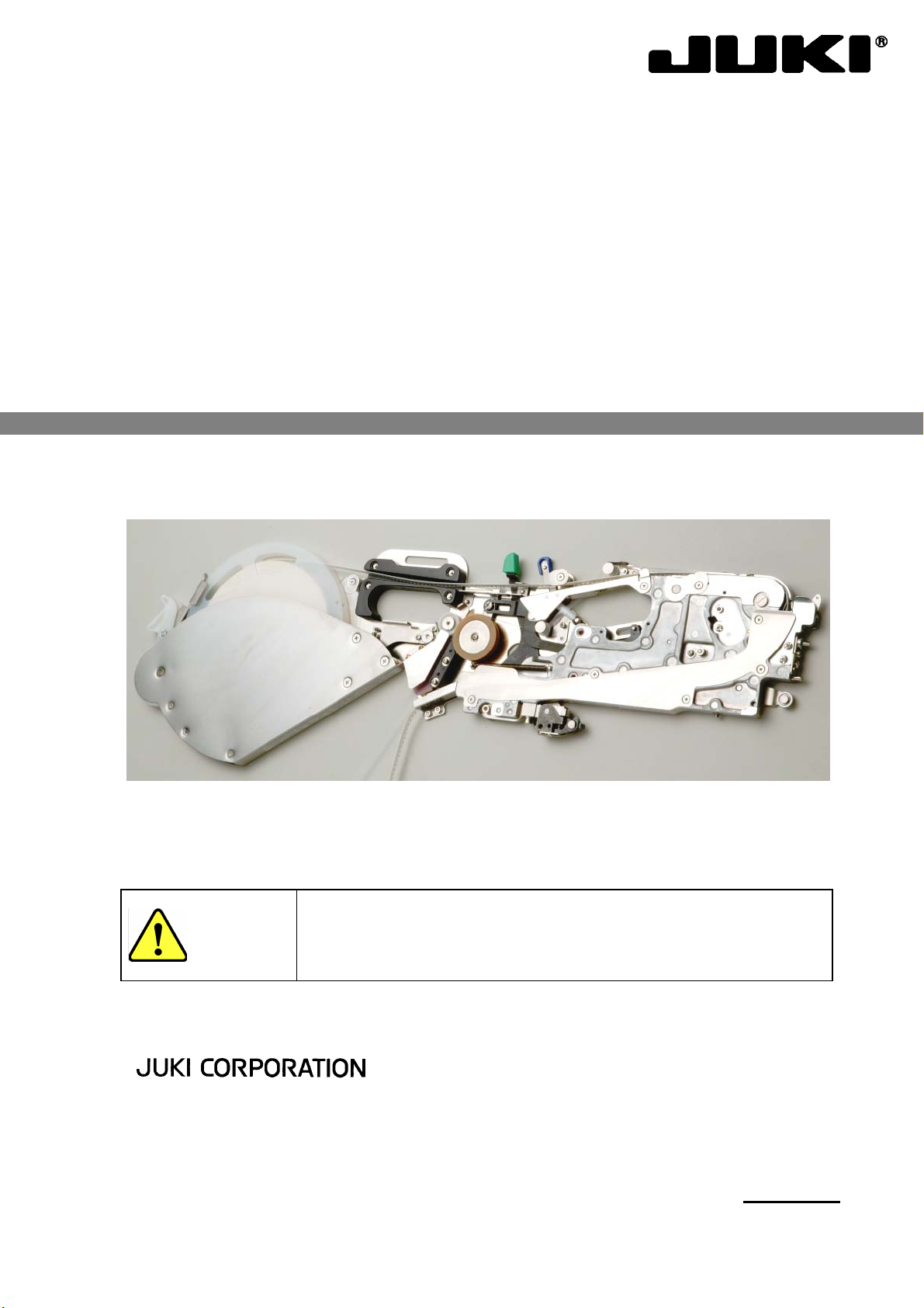
1.3 Name of Each Part......................................................................................................... 2
2. How to Use..................................................................................................4
2.1 Attaching or Detaching the Tape Reel........................................................................... 4
2.1.1 How to attach the tape reel..................................................................................4
2.1.2 Removing a tape..................................................................................................8
2.2 Carrying the Tape Feeder.............................................................................................. 9
2.3 Feeding a Component (Enabling a Component To Be Picked Up)............................... 9
2.4 Splicing........................................................................................................................... 10
2.4.1 Specifications of a splice tape .............................................................................10
2.4.2 How to splice tapes .............................................................................................10
2.5 Attaching or Detaching the Tape Feeder onto a Mounter ............................................. 15
3. Daily Inspection..........................................................................................16
3.1 List of Daily Inspection Items ......................................................................................... 16
3.2 Where to Inspect............................................................................................................ 17
3.3 Where to Clean .............................................................................................................. 20
3.4 Where to Lubricate......................................................................................................... 23
3.5 Parts to Be Replaced Regularly..................................................................................... 24
3.5.1 List of parts to be replaced regularly ...................................................................24
3.5.2 How to replace a part that is to be replaced regularly.........................................24
4. Options........................................................................................................28
4.1 Bar Code Tag................................................................................................................. 28
4.1.1 Attaching a bar code tag......................................................................................28
4.2 Embossed Tape Spacer ................................................................................................ 29
4.2.1 Pasting an embossed tape spacer ......................................................................29
4.2.2 Combination of the embossed tape spacer thickness.........................................29
4.3 Joint tape........................................................................................................................ 30
4.4 Tape reel attaching platform .......................................................................................... 30

ATF Instruction Manual
1
1. Overview
This product is an 8-mm tape feeder (ATF) designed for our high-speed flexible
mounters KE-2050/2060/2050R/2055R/2060R or FX-1/FX-1R, and allows you to feed
components at high speed and with a high degree of accuracy and splice tapes. It is
a component feeder that arranges and feeds components supplied by a tape to the
pick-up position.
This tape feeder can be used with the conventional mounters,
KE-2010/2020/2030/2040 or KE-750/760 also.
AQ02HP is available with KE-2050/2060/2050R/2055R/2060R or CX-1 mounters only.
1.1 Features
(1) Since this tape feeder is driven with the air cylinder (drive cylinder) with which a
mounter is equipped, it does not require any air or power supply, and you can
handle it easily.
(2) Its “shutter mechanism” allows parts to be fed more stably.
(3) Its “toggle clamp mechanism” improves the part pick-up position accuracy.
(4) It can “splice” (connect tapes together) tapes that supply components.
* AQ02HP does not support any splicing function.
1.2 Specifications
Tape type
Product code Paper Emboss
ed
Feeding
pitch
(mm)
Release lever
color
Number of pins
at the edge
(Handle color)
Reel
diameter
(mm)
Typical component
type
AQ02HP Pressed pocket
type tape only −Dark pink 0402 only
AF05HP ○− Light green 1005
AF08HE −○
2
Blue Two-terminal diode
AF081P ○− Dark green 1608、2012、3216
AF081E −○4 Light blue
2 (Black)
SOT
AN05HP ○− Light green 1005
AN08HE −○2 Blue Two-terminal diode
AN081P ○− Dark green 1608、2012、3216
AN081E −○ Light blue SOT
AN081C ○○
4
Black
1 (White)
180
1608、2012、3216
Number of occupied positions 2
Power/Air supply None/None
Dimensions L=645mm, W=16.8mm, H=213mm
Mass 1.8 kg or less (excluding a reel)
Pick-up position accuracy ± 0.05 mm (See Notes 1 and 2.)
Parts feeding method Ratchet driven method
Note 1: When a JUKI jig tape is used.
Note 2: The pick-up position accuracy varies depending on the accuracy of the tape you use.
Note 3: When you use a feeder bank for KE-750/760 or KE-2010/2020/2030/2040, or when
you use an AN081C (for both paper and embossed tapes), you have to perform
teaching operation depending on the thickness of a tape.
CAUTION Use a tape feeder designated for components.
If you use components not applicable to the tape feeder, the tape feeder
cannot operate normally and this may damage the feeder itself.

ATF Instruction Manual
2
1.3 Name of Each Part
20 19 17 21 11 18 14 15 1
10 9 12 13 16 2
Figure 1.1
Figure 1.2
13864 3
Section B
Section A
7
5
1 X-axis reference pin A 12 Lock holder
2 X-axis reference pin B 13 Cross roller
3 Upper cover 14 Guide roller
4 Upper cover hook 15 Tape guide
5 Knock lever 16 Guide cover
6 Shutter 17 Reel support
7 Stopper 18 Manual feeding lever
8 Free link 19 Reel support arm
9 Delivery roller 20 Reel brake
10 Retaining roller 21 Cover tape feeding lever
11 Release lever

ATF Instruction Manual
3
Detailed figure of the section A 23
24
22
25
Figure 1.3
Detailed figure of the section B
26 27
29
28
Figure 1.4
22 X-axis adjustment shaft 26 Lock holder
23 Sprocket wheel 27 Plunger plate
24 Ratchet hook adjustment
eccentric collar
28 Toggle pressure adjustment lock pin
25 Ratchet hook stopper 29 Lock holder Y adjustment lock pin
CAUTION If you do not have any feeder inspection jigs, do not disassemble any parts.
Without a jig, you cannot make correct adjustment to reassemble the parts.

ATF Instruction Manual
4
2. How to Use
2.1 Attaching or Detaching the Tape Reel
2.1.1 How to attach the tape reel
1) Push the upper cover hook in the
direction indicated with the arrow mark to
unhook the upper cover.
Upper cover hook
Figure 2.1.1
2) Lift the upper cover in the direction
indicated with the arrow mark to make
preparations for setting a tape.
Figure 2.1.2
Upper cover
3) Hold down the reel brake in the direction indicated with the arrow mark (see
Figure 2.1.3), set a tape into the reel support shaft, and store it into the reel
support.
Reel support
Outer flange section of the tape reel
Reel brake
Figure 2.1.3 Figure 2.1.4 Figure 2.1.5
CAUTION
Check to see if the outer flange section of the tape reel is in contact with
the reel brake when you attach the reel brake (see fig. 2.1.4, 2.1.5).
If the reel brake is not attached correctly, the tape feeder cannot function
normally.

ATF Instruction Manual
5
4) Thread the carrier tape through the path located on the feeder upper section (in
the direction indicated with the arrow mark) (see Figure 2.1.6), and pull it out to
the bottom of the upper cover. Then, thread the cover tape through the peel-off
slit of the upper cover (see Figure 2.1.7), and close the upper cover.
Check to see if the upper
cover is hooked normally.
Check to see if the feeding teeth of
the sprocket wheel are engaged
into the holes of the carrier ta
p
e.
Peeling slit
Figure 2.1.6 (Upper left), Figure 2.1.7 (Upper right),
Figure 2.1.8 (Lower left), Figure 2.1.9 (Lower right)
CAUTION
•When closing the upper cover, check to see if the teeth of the
sprocket wheel for feeding tape are engaged into the holes of the
carrier tape (see fig. 2.1.8).
If the teeth for feeding tape are not engaged into the holes of the
carrier tape, the tape feeder cannot feed tape normally.
•When closing the upper cover, check to see if the upper cover is
hooked normally (see fig. 2.1.9).
If the upper cover is not attached correctly, the tape feeder cannot
function normally.
•When setting the carrier tape, check to see if the edge of the tape is
not jammed (wrinkled or folded). If the edge is jammed, the tape
feeder may not feed the carrier tape normally.

ATF Instruction Manual
6
5) Thread the cover tape over the guide roller, cross roller, cross roller and guide
roller in this order (①→②→③→④) (see Figure 2.1.12) so that the tape
cannot be twisted, and place the cover tape around the delivery roller while
pushing the retaining roller arm in the direction indicated with the arrow mark to
tuck the tape under the retaining roller (see Figure 2.1.11).
Figure 2.1.10
Manual feeding lever
Figure 2.1.11 Figure 2.1.12
CAUTION
•Be sure to set the cover tape via the guide roller and the cross roller. If you do
not set the cover tape correctly, the tape feeder may not feed the tape normally.
•Thread the cover tape so that its adhesive side can face the retaining roller.
If the adhesive side faces the delivery roller, the tape feeder may not feed the tape
normally.
•Tuck down the cover tape so that it cannot be put into the groove of the delivery
roller. If the cove r tape is put into the groove, the tape feeder may not feed the
tape normally.
•You can set a tape only if the length of the cover tape lead section is 300 mm or
longer. If the length is shorter than this, splice the front edge of the lead section
with an adhesive tape to extend the length. (See page 7.)
6) Feed a component with the manual-feed lever until it reaches the opening of the
upper cover.
CAUTION
When feeding a component manually, check to see if the tape is not fed
further than the peel-off slit.
If the cover tape is fed further than the peel-off slit, the tape feeder
cannot feed the tape normally.
④
Retaining roller arm
Retaining roller Where to roll the
ta
p
e ove
r
②
③Cross roller
Delivery roller
Guide roller
①

ATF Instruction Manual
7
●Setting a tape if the cover tape is short
To wrap the cover tape around the delivery roller, the lead length must be
approximately 300 mm or longer. If the length is shorter than 300 mm, splice the front
edge of the lead section with adhesive tape to extend the length.
(If you use a new tape, you can use the adhesive tape stuck to the front edge of the lead.)
Note: The international standard (IEC60286-3) and JIS (Japanese Industry
Standards) regulate that the lead length should be 400 mm or longer. If you
use the tape that conforms to these standards, you do not have to splice the
front edge of the lead section.
Note: If you splice the front edge of the lead section with adhesive tape to extend its
length, set the cover tape so that its adhesive side can face the retaining
roller (see the figure below).
Delivery roller
Adhesive tape
Adhesive side of the cover
Adhesive side of the
cover tape (spliced)
Retaining roller
●How to operate the cover tape feeding lever
When you push the cover tape feeding lever in the direction “A,” you can feed the cover
tape only. Operate this lever to tension the cover tape after attaching the tape feeder
onto the feeder bank.
Manual feeding lever
Cover-tape feeding lever
A
Note: To feed a carrier tape, use the manual feeding lever.
If you use the cover-tape feeding lever to feed a carrier tape, the tape feeder
feeds it too much, and the component pick-up position error may occur.

ATF Instruction Manual
8
2.1.2 Removing a tape
1) Push the retaining roller arm in the direction indicated in the figure to remove a
tape.
Retaining roller arm
Figure 2.1.13
2) Push the upper cover hook in the direction indicated in the figure to unhook the
upper cover.
Figure 2.1.14
3) Lift up the upper cover in the direction indicated in the figure to remove a tape.
Figure 2.1.15
4) Close the upper cover.

ATF Instruction Manual
9
2.2 Carrying the Tape Feeder
Grasp the grip section of the tape feeder securely to carry it.
Gri
p
section Section “A”
Figure 2.2.1
CAUTION
•When carrying the tape feeder, do not grasp the section “A.” If any
abnormal load is imposed on the section “A,” the tape feeder may be
deformed, and it may cause the component feeding error or pickup.
•When carrying the tape feeder, take extreme care so that you cannot hit
it against any other parts or equipment or drop it.
If any shock is given to the tape feeder by any possibility, be sure to
check to see if the tape feeder does not.
2.3 Feeding a Component (Enabling a Component To Be Picked Up)
Level the tape feeder, and operate the manual feeding lever or knock lever in the
direction indicated with the arrow mark to feed a component and stop it nearby the
pick-up position. If a component is located at the pick-up position before you attach
the tape feeder onto the mounter, the component may drop off due to vibration of the
tape feeder when you are carrying the tape feeder or when you attach it onto the
mounter. Therefore, feed a component to the pick-up position only after attaching the
tape feeder onto the mounter.
Manual feeding lever
Pick-up position
Knock lever
Figure 2.3.1
CAUTION Be sure to feed a component to the pick-up position only when the
mounter does not operate. Check to see if the component is located at
the pick-up position or if it is not shifted from the pick-up position.

ATF Instruction Manual
10
2.4 Splicing
This tape feeder allows you to splice the tape on which only a few components
remain and a new tape without stopping the mounter that is operating.
* AQ02HP does not support any splicing function.
2.4.1 Specifications of a splice tape
Be sure to splice tapes we specified only.
However, you can use a tape on the market that satisfies the regulated requirements
for some models indicated in Table 2.4.2 also.
Table 2.4.1
Width JUKI specified tape part number
5mm E9031706AA0
Table 2.4.2
Model name Detailed requirements for tapes on the market
AF081E
AN081E
AF081P
AN081P
AN081C
-Total thickness of a tape
(Basic material + Adhesive material): 0.06 mm or thinner
-Adhesive strength: 4.2 N/10 mm or higher
Note: Store a splice tape in the environment whose temperature is 30ºC or lower and
that is not exposed to direct sunlight. Use it in six months after you purchase it
without leaving it for a long time.
2.4.2 How to splice tapes
1) When the length of the remaining section of the
tape you use becomes approximately 1.5 m to
2 m, pull and raise the reel support arm to pull
out a tape.
Figure 2.4.3
2) As shown in the figure below, vertically cut the tape you are using at the position
after the feeding hole that is located immediately after the last component.
カバーテープが剥が
れていないこと
The cover tape should
not be peeled off.
切断
Cut here.
Figure 2.4.4
CAUTION When you cut the tape, use a pair of scissors to cut it neatly and
vertically.

ATF Instruction Manual
11
Cover tape
3) After you pull the cover tape of a new component to the first component position
to peel it off, cut the tape without with leaving one cavity in which any component
is not located.
①Pull the cover tape to the first component position to
p
eel it off.
②Cut the tape here.
First component position
Cavity in which no
component is located
Cavity in which no
component is located
First component
position
Cut the tape here.
Figure 2.4.5
CAUTION
When you cut the tape, use a pair of scissors to cut it neatly and
vertically.
If each interval between holes of the carrier tape of the spliced section is
not the same with each other after you splice tapes, the tape feeder
cannot feed a tape normally.
CAUTION
•If you do not peel off the cover tape from the front edge of the tape,
the tape feeder cannot feed the tape normally.
•When you peel off the cover tape from the front edge of the tape, take
care so that any elements cannot turn.
4) Use a waste rug or cotton-tipped swab moistened with IPA (isopropyl alcohol) or
ethanol to remove any oil or dust stuck to the surface of the cover tape that is to
be pasted on a splice tape.
5) Cut the splice tape by approximately 40 mm, and paste its half portion over the
cover tape of a new tape securely. Note that the splice tape should not stick out
to the carrier tape as much as possible.
Approximately 40 mm
Approximately 20 mm
Cover tapeCarrier tape
Splice tape
(Cut
t
h
e
edge
d
i
ago
n
a
ll
y
.
)
Figure 2.4.6
CAUTION Use a pair of scissors to cut the edge of the splice tape diagonally.
If you cut it vertically, the peel-off slit of the upper cover may peel off the
splice tape.

ATF Instruction Manual
12
6) Cover the end of the tape you are using with the front edge of the new tape, and
paste the latter half of the splice tape over the cover tape securely.
Ta
p
e alread
y
usedPaste the splice tape only after
aligning the edge of the cut tape
with the tape already used
New ta
p
e
Figure 2.4.7
CAUTION Check to see if all hole-pitches of the carrier tape in the vicinity of the
spliced section are the same with each other. If any pitch is different
from another one, the tape feeder cannot feed a tape normally.
7) Cut the splice tape by approximately 40 mm, and securely paste each half portion
over the carrier tape of the new tape and that of the tape already used.
カバーテープ面
キャリアテープ面
40mm程度
接続用テープ
Cover tape
Splice tape Carrier tape
Approximately 40 mm
Figure 2.4.8
8) Rewind the spliced tape around the reel of the new tape, set the reel into the reel
support shaft, and store it in the reel support.
CAUTION Use a waste rug or cotton-tipped swab moistened with IPA or ethanol to
clean the peel-off slit of the upper cover approximately once a week. (See
Section 3 “Daily Inspection.”)

ATF Instruction Manual
13
●When you splice am embossed type of carrier tape
When you splice an embossed type of carrier tape, use a joint tape after splicing tapes
normally. It is useful to splice tapes stably.
1. Paste a joint tape over the carrier tape as shown in the figure below, and cut the
pasted tapes so that the width can become approximately 3 mm.
2. Paste a cut joint tape on the position shown in the figure below so that it can wrap
around the tape closely. Note that you have to paste the joint tape so that it
cannot cover a half or more area of each feeding hole.
3mm程度
半分以上穴を
塞がないこと
Approximately 40 mm
Do not cover a
half or more area
of each hole. Approximately 3 mm
カバーテープ面
Cover ta
p
e
キャリアテープ面
40mm程度
接続用テープ
Splice tape Carrier tape 半
塞
分以上穴を
がないこと
Do not cover a half
or more area of
each hole.
A
pp
roximatel
y
40 mm
キャリアテープに密着するように貼付けること
Paste the joint tape so that it can be stuck to the carrier tape closely.
断面図
Cross-sectional view
This manual suits for next models
4
Table of contents
Other JUKI Industrial Equipment manuals

JUKI
JUKI JaNets JT Simple User manual

JUKI
JUKI 72005824 User manual

JUKI
JUKI FX-1 Operating manual

JUKI
JUKI ACF-164-1903 Quick start guide

JUKI
JUKI KE-2070 User manual

JUKI
JUKI PS-900-13090 User manual

JUKI
JUKI PS-800SB-8045 User manual

JUKI
JUKI M92 Manual

JUKI
JUKI LK-1900B series Instruction Manual

JUKI
JUKI AW-3S User manual
Popular Industrial Equipment manuals by other brands

McElroy
McElroy DynaMc HP Series Operator's manual

SMC Networks
SMC Networks EX510-DYN3 instruction manual

ABB
ABB HT611671 Operation manual

Comco
Comco MicroBlaster MB1005 Operation and service instructions

stellar labs
stellar labs TireMan 4110 owner's manual

AndyMark
AndyMark Climber in a Box Assembly guide