Plockmatic HCI3500 User manual

Read this manual carefully before you use this product and keep it handy for future
reference.
For safety, please follow the instructions in this manual.
Doc no: X04105B
Date: 24 January 2017
Operating Instruction
Plockmatic HCI3500
High Capacity Interposer

WARNING:
This is a Class A product. In a domestic environment this product may cause radio
interference in which case the user may be required to take adequate measures.
The product (System) which is connected to this machine will be class A.
NOTE:
The domestic environment is an environment where the use of broadcast radio and
television receivers may be expected within a distance of 10m of the apparatus concerned.

Introduction
This manual contains instructions on the operation and maintenance of this machine. To
get maximum versatility from this machine all operators should carefully read and follow
the instructions in this manual. Keep this manual in a handy place near the machine.
Please read the Safety Information before using this machine. It contains information
related to USER SAFETY and PREVENTING EQUIPMENT PROBLEMS.
How to Read This Manual
Notation Conventions
Whenever necessary, the following points for attention are indicated in this manual.
WARNING:
Indicates a potentially hazardous situation which, if instructions are not followed,
could result in death or serious injury.
CAUTION:
Indicates a potentiality hazardous situation which, if instructions are not followed, may
result in minor or moderate injury or damage to machine or property.
NOTE:
This sign refers to:
• Remarks for making the operation much easier. You get practical hints or knowledge to
assist you in the machine operation such as:
• Preparations required before operating
• How to prevent papers from being misfed or damaged
• Precautions required or actions to take after misoperation
• Limitations like numerical limits, functions that cannot be used together or conditions,
under which a particular function cannot be used or obtained.
• Information.
[ ]
Keys that appear on the machine’s display panel.

WARNING:
• To avoid hazardous situations like for instance electric shock or danger while exposed
to moving, rotating or cutting devices, do not remove any covers, guards or screws
other than those specied in this manual.
• Turn off the power and disconnect the power plug (by pulling the plug, not the cable) if
any of the following conditions exists:
• You drop objects or spill something into the equipment.
• You suspect that your equipment needs service or repair.
• Your equipment’s covers has been damaged.
• You notice unusual noises or odours when operating the equipment.
• If the power cable or plug becomes worn out or otherwise damaged.
• Before cleaning and care (unless otherwise specically instructed).
• Electromagnetic compliance:
• This is a Class A product. In a domestic environment this product may cause radio
interference in which case the user may be required to take adequate measures.
• The product (System) which is connected to this machine will be class A.
Safety Information
When using this machine, following safety precautions should always be followed.
Safety During Operation
General Safety
WARNING:
• Always connect the equipment to a properly grounded power source (wall outlet). If in
doubt, have the power source checked by a qualied electrician.
• Improper grounding of the equipment can result in electrical shock. Never connect the
machine to a power source that lacks a ground connection terminal. This machine is
destined for specic purpose only. Any use going beyond this specic purpose is re-
garded as beyond the determination. The manufacturer will not be liable for damages
resulting from any use beyond the determination, unallowed operation, respectively.
The user alone bears the risk.
• Do not make arbitrary changes or modications to the machine. The manufacturer will
not be liable for modications made at the machine on your own and damages result-
ing thereof. EC declaration of conformity and the mark CE will be invalidated, if you
make changes at the machine or at the individual components.
• Do not override or bypass electrical or mechanical interlock devices.
• The machine is to be used only by authorized and instructed persons. The responsibil-
ities on operating the machine have to be strictly laid down and observed so that there
are no unclear competences regarding safety aspects.
• Vent holes serve for air circulation to protect the machine from overheating. Make sure
that the holes are not covered.
• Do not expose ngers or other parts of the body to moving, rotating or cutting devices
such as for instance between upper and lower trimmer knives.
• Always locate the equipment on a solid support surface with adequate strength tor the
weight of the machine.

NOTE:
• The operator manual always has to be available at the place of use of the machine.
• In the interest of technical development the company reserves the right to make
alterations to specications without prior notice!
CAUTION:
• The machine and its peripherals must be installed and maintained by a customer service
representative who has completed the training course on those models.
• Always follow all warnings marked on, or supplied with, the equipment.
• When you disconnect the power plug from the wall outlet, always pull the plug (not the cable).
• Disconnect the power cord before you move the machine. While moving the machine, always
exercise care and make sure that the power cord will not be damaged under the machine.
• Always contact service if relocating the equipment.
• Do not move the machine while the machine is running.
• Do not open covers while the machine is running.
• Do not switch off the power while the machine is running. Make sure the machine cycle has
ended.
• Lay the power cord in a way that nobody will stumble over it. Do not place things on the cord.
• Never attempt any maintenance function that is not specically described in this
documentation.
• Always keep magnets and all devices with strong magnetic elds away from the machine.
• If the place of installation is air-conditioned or heated, do not place the machine where it will be:
• Subject to sudden temperature changes.
• Directly exposed to cool air from an air-conditioner.
• Directly exposed to heat from a heater.
• If the machine is not used over an extended period of time it should be unplugged to prevent
damage in the case of overload.
General Safety (Continued)

Page intentionally blank.

TABLE OF CONTENTS
What You Can Do With This Machine .................................................. 9
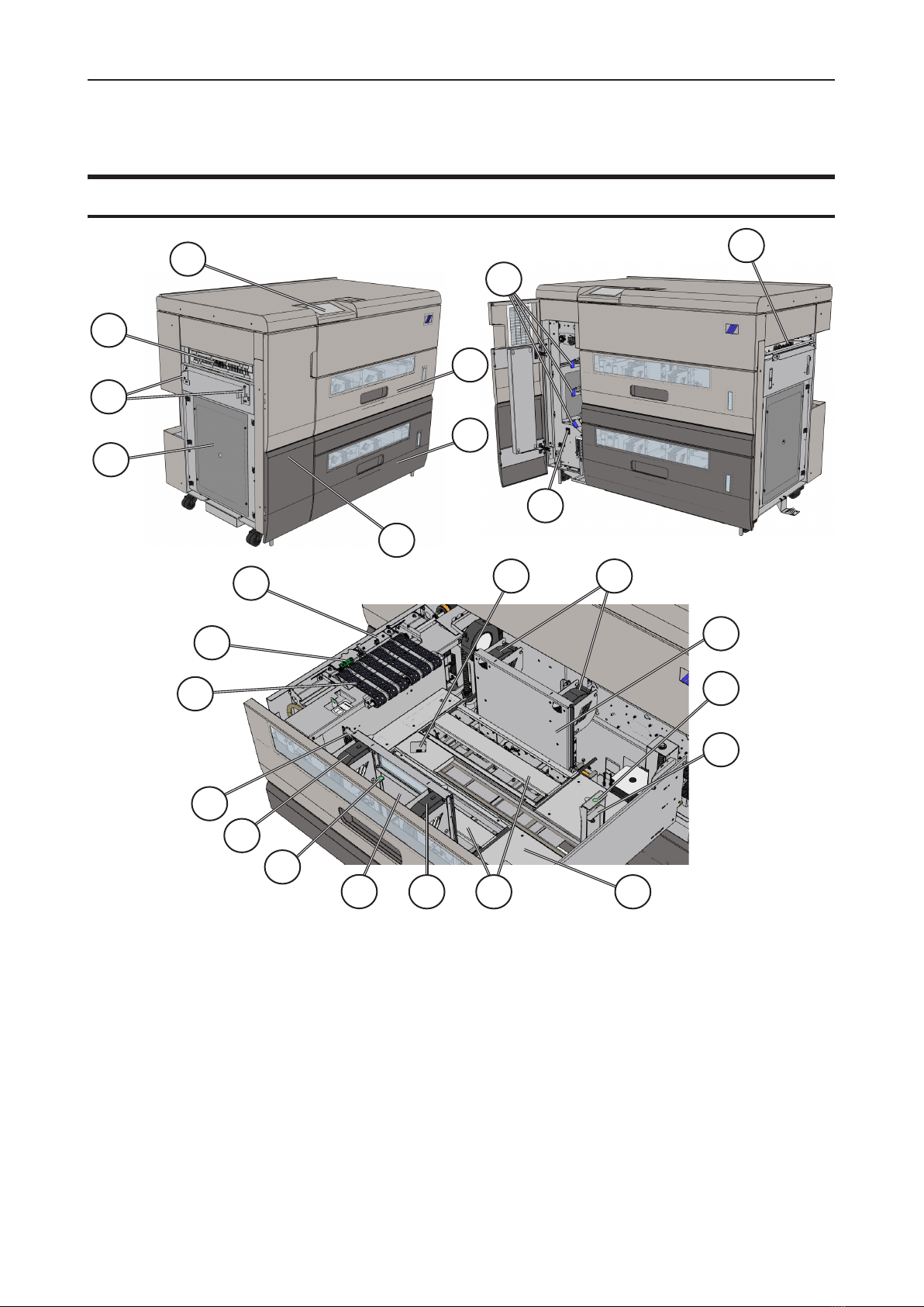
Guide To Components ..................................................................................................... 11
HCI3500...................................................................................................................................... 11
User Interface ............................................................................................................................. 14
1. Basics............................................................................................... 17
Turning On / Off the Power .............................................................................................. 17
Calibration......................................................................................................................... 18
Job Preparation ................................................................................................................ 19
Paper stack preparation.............................................................................................................. 19
Measuring the paper curl ............................................................................................................ 21
Loading Paper ............................................................................................................................ 22
2. Setting Up a Job .............................................................................. 25
Settings Sub-Menus......................................................................................................... 25
Settings....................................................................................................................................... 25
Tray A/B ...................................................................................................................................... 25
Auto Fans / Manual Fans............................................................................................................ 26
Paper Curl................................................................................................................................... 26
DSD Sensors .............................................................................................................................. 27
Advanced.................................................................................................................................... 28
Manual Fans Adjustment ............................................................................................................ 28
Process Position ......................................................................................................................... 31
Saving changes .......................................................................................................................... 32
3. Tools ................................................................................................. 33
The Tools Menu ................................................................................................................ 33
Units............................................................................................................................................ 33
Language.................................................................................................................................... 33
Test ............................................................................................................................................. 34
Calibrate DSD and Ultrasonic DSD ............................................................................................ 34
Service Mode.............................................................................................................................. 34
Software version ......................................................................................................................... 35
4. Jobs .................................................................................................. 37
Handling jobs.................................................................................................................... 37
Loading a Job ............................................................................................................................. 37
Saving a Job ............................................................................................................................... 38
Saving a New Job....................................................................................................................... 38
Deleting a Job............................................................................................................................. 38
5. Clearing Misfeed(s) ......................................................................... 39
Clearing Misfeed(s) .......................................................................................................... 39
Misfeed / Jam in Feeder Tray ..................................................................................................... 39
Misfeed / Jam in Paper Transport Area ...................................................................................... 39
Misfeed / Jam in Infeed / Bypass Area ...................................................................................... 39

6. Troubleshooting .............................................................................. 41
HCI3500 Fault codes ........................................................................................................ 41
General ....................................................................................................................................... 41
HCI3500 Fault Codes ................................................................................................................. 42
Jam recovery manual setting...................................................................................................... 46
Miss error .............................................................................................................................................. 46
Jam, Too long, Too thick errors ............................................................................................................. 47
Sensor Calibration ...................................................................................................................... 48
7. REMARKS ........................................................................................ 51
Do’s And Don’ts................................................................................................................ 51
Where to Put Your Machine ............................................................................................. 52
Machine Environment ................................................................................................................. 52
Power Connection ...................................................................................................................... 52
Access to Machine...................................................................................................................... 53
Maintaining Your Machines ............................................................................................. 54
HCI3500 Maintenance ................................................................................................................ 54
Cleaning HCI3500................................................................................................................................. 54
Limitations of the HCI3500 .............................................................................................. 56
8. Specications ................................................................................. 57
HCI3500 ............................................................................................................................. 57
Declaration of Conformity HCI3500 ................................................................................ 60

9
What You Can Do With This Machine
Upstream Printers
Ricoh Pro 8200 Series
Other future printers
Stackers / Multiple
Ricoh Finishing
Devices
HCI3500
The Plockmatic HCI3500 High Capacity Interposer is a newly engineered option for Ricoh
Production printers. The HCI3500 attaches inline and is compatible with multiple Ricoh
printers and downstream modules.
The design of the Plockmatic HCI3500 is tailored specically to complement Ricoh printing
systems and provides features that set Ricoh systems apart from their competitors.
The HCI3500 utilizes the latest Plockmatic vacuum feed technology for efcient paper
feeding and is equipped with a state of the art touchscreen GUI.
The HCI3500 contains two paper trays and a paper bypass route, which allows for custom
sequencing of sheets from three different sources (the two trays and the printer output).
This means that ofine pre-printed media of varying types and formats can be integrated
into the workow. Ultimately, this results in the elimination of hand feeding covers and in-
serts into the nishing process.
The Plockmatic HCI3500 effectively widens the range of media types/sizes that Ricoh sys-
tems can handle. The HCI can reliably feed media all the way up to 350gsm.
The HCI3500 integrates seamlessly with the Ricoh printing systems and is setup and con-
trolled either from the Ricoh printer User Interface or from the Fiery controller if a Fiery is
available in the conguration.

10
Guide To Components
HCI3500
1 Exit Area
2 Docking Plate
3 Exit Side Cover Plate
4 Upper Tray / Tray A
5 Lower Tray / Tray B
6 Front Door
7 Jam Clearance Bafes (blue)
8 Power Switch
9 Bypass Inlet
10 Paper Guide Lock Release
11 Paper Guide Fans
12 Vacuum Feed Belts
13 Optical Double Sheet Detection
(DSD) Sensor (Q101/201)
14 Ultrasonic Double Sheet
Detection (DSD) Sensor
(Q102/202)
15 Tray Empty Sensors
(Q105/Q205)
16 Rear Paper Guide (RPG)
17 RPG Lock Release
18 Elevated Tray Bottom
19 SP Sensor (Process Position
Sensor)
20 Paper Guide
21 Wide Paper Support
22 Graphical User Interface
8
9
7
1
22
2
3
6
5
4
10
11
16
20
17
18
11
19
12
14 15
21
20
13
11

11
Guide To Components (Continued)
HCI3500 Top View
21 Exit Sensor (Q303)
22 Paper Infeed Sensor (Q310)
23 Paper Path Detection Sensor (Q311)
24 Bypass Bafe
25 Bypass Bafe, Infeed
26 Bypass Bafe, Exit
27 Exit Module (not visible, located under the
bafe)
2327
222521 2426
*Top cover removed for clarity

12
Guide To Components (Continued)
HCI3500 Upper Support Assembly
27 Ultrasonic Distance Sensor (USDS) (Q301/302)
28 Upper Support Assembly
27
28
*Top tray removed for clarity

13
User Interface
Main Menu
When the system power is switched
on, the Main Menu will be shown.
From the Main Menu one can access
the Settings, Tools, Counter, and
Jobs sub-menus from the top ribbon
interface. Selecting ‘Home’ from any
sub-menu will bring the user back to
the Main Menu.
The Main Menu displays the
current loaded job, paper inventory
percentage in each tray, and any
relevant error information. It also
has buttons which unlock the trays
for paper loading.
Settings
Pressing the [Settings] button from
the Main Menu opens the Settings
sub-menu. From here you can
view and/or modify performance
parameters.
See Section 2 for a detailed
description of each Setting.
The control panel is of touch screen type. Point at the screen and press the “button” to
reach the desired function or change the desired setting.
The Plockmatic HCI3500 has a Graphical User Interface (GUI) / Control Panel which allows for
viewing or adjusting local machine settings and properties. In other congurations where the
HCI3500 is connected to an upstream printer or device, setting up a job will be handled via the UI
of the upstream device.
NOTE:
Depending on modules and features installed, the screen may look different from what you
see here. Some functions are greyed out or not visible at all and remaining buttons may
stretch to t the screen. This manual will most often show a fully congured system.
Control Panel

14
Tools
Pressing the [Tools] button from the
Main Menu opens the Settings sub-
menu. From this sub-menu the user
can modify parameters such as Units
and Language.
This sub-menu also allows the user
to test the manual settings, calibrate
sensors, enter service mode, and
check the Software version.
See Section 3 for a detailed
description of each sub-menu within
the Tools sub-menu.
Counter
The Counter sub-menu contains
three different counters. The trip
counter can be reset at any time
by pressing the [0] on the number
pad and will increment after each
sheet until it is reset again. The tray
counters tally the total amount of
sheets from each tray.
Jobs
The Job sub-menu allows for
programming of jobs when the
HCI3500 is used as primary feeder.
If the HCI3500 is connected to an
Upstream Printer or other device,
jobs will be programmed using the
user interface of the upstream device
and the HCI3500 Jobs sub-menu will
be disabled.
See Section 4 for a detailed
description of the Jobs sub-menu.

15
A
Turning On / Off the Power
Main Power Switch
1
Ensure that the main power cord is
plugged into the wall and to the back of
the HCI3500.
2
Make sure the two shorting plugs are
plugged in, as shown in the picture.
1. Basics
NOTE:
The HCI3500 contains two power switches (Service and Main). The default position for
the Service Power Switch is ‘off’. If the Service Power Switch is ‘on’, the HCI3500 will
be able to power up as a standalone unit, but will ignore power on signals from upstream
devices. If this is occuring, contact a service technician to turn off the Service Power
Switch.
3
Open the front door
4
Toggle on/off the Main Power Switch [A]

16
1
Sensor Calibration
Calibration
The HCI3500 has two types of double sheet detection (DSD): optical and ultrasonic. The
machine also contains a Ultrasonic Distance Sensor (USDS). If feed errors begin occuring
more frequently, these sensors may need to be calibrated. Refer to Section 6 for full cali-
bration details and instructions.
Ultrasonic Double Sheet
Detection Sensor
Optical Double Sheet
Detection Sensor

17
1
Paper stack preparation
Job Preparation
1
Hold the paper stack on a at surface
as shown
2
Bend the paper stack
3
Use your ngers and thumbs to pinch
the paper stack
4
With the paper pinched between your
ngers, straighten out the paper stack
Continued on next page...

18
1
Paper stack preparation (continued)
5
Flex the paper back and forth a couple
of times to break surface tension and
preseparate the sheets
6
Realign the sheets into a stack before
putting them into the tray

19
1
YES!
NO!
Measuring the paper curl
Take a sample of the stack (about 15 mm / 0.59” high) and place it on a at surface
1
Take the midpoint as reference and
do all the measurements within the
marked area of the picture (from the
center to the leading edge in paper
feed direction)
2
Measure the lowest point of the stack
of paper
3
Measure the leading edge height
of the stack of paper: the difference
between the leading edge and the
lowest point is the amount of paper
curl
NOTE: always measure the positive
curl of a stack of paper, meaning that
the leading edge of the stack should be
pointing up as shown in the picture.
If the paper needs to be loaded in the
trays with the edge pointing down, insert
the negative curl amount on the GUI.
Measure within this area
This procedure can also be used to
measure the cross process direction curl.

20
1
Loading Paper
1
From the Main Menu, select Load tray A,
Load tray B or Load tray A/B depending
on which tray you intend to open and load.
Tray A is the upper tray
2
Lift the Paper Guide lock release levers
[A], move the Paper Guides [B] inwards
and adjust them according to the size of
the paper: see label [E]. If the paper stack
is wider than 260 mm / 10.24” install the
Paper Supports [F]
3
Prepare the stack of paper following
the procedure described in the “Job
preparation” section
4
If running jobs in “auto mode”, measure
paper curl and insert value in the GUI
5
Place the sheets on the elevated tray
bottom [C]. Place the leading edge of the
sheets against the Separation Frame [D],
underneath the vacuum belts.
Continued on next page...
A
A
B
F
B
B
EC FD
8½
8
11
12
A5
A4 A5
A3 A4
SRA3
5½
B4 B5
B5
2016-11-14
HCI3500
131-110717B
AD
PS 1 1:1 A4 --
RoHS-compliant
Fri från sexvärt krom
Free from hexavalent chrome
Notes
Design dat.
Doc. No.
Art. no.
FormScale
Adhesive
Gen. tol. Rev. dat.
Title
Material
Dim.
-
McDermid Autotex Velvet V207
Tray Paper Alignment Label
3M 468MP 0,127mm
NCS S 9000-N
NCS S 3000-N
30mm
123,5mm
2mm
Myriad Pro, Semi Bold
Black:
Grey:
Width:
Height:
Rounded Corners:
Fonts:
8½
8
11
12
A5
A4 A5
A3 A4
SRA3
5½
B4 B5
B5
Other manuals for HCI3500
1
Table of contents
Other Plockmatic Industrial Equipment manuals

Plockmatic
Plockmatic MPS XL User manual

Plockmatic
Plockmatic Morgana VFL Feeder User manual

Plockmatic
Plockmatic FeederPro 1000 User manual

Plockmatic
Plockmatic BM3000 User manual

Plockmatic
Plockmatic SF 4000 User manual

Plockmatic
Plockmatic Morgana PowerSquare 160 User manual

Plockmatic
Plockmatic 510 User manual

Plockmatic
Plockmatic Pro XL User manual

Plockmatic
Plockmatic HCI3500 User manual