© MDM INCORPORATED
WWW.MDMINC.COM
Reliable. Efficient.
PROUDLY MADE
IN THE USA
®
750
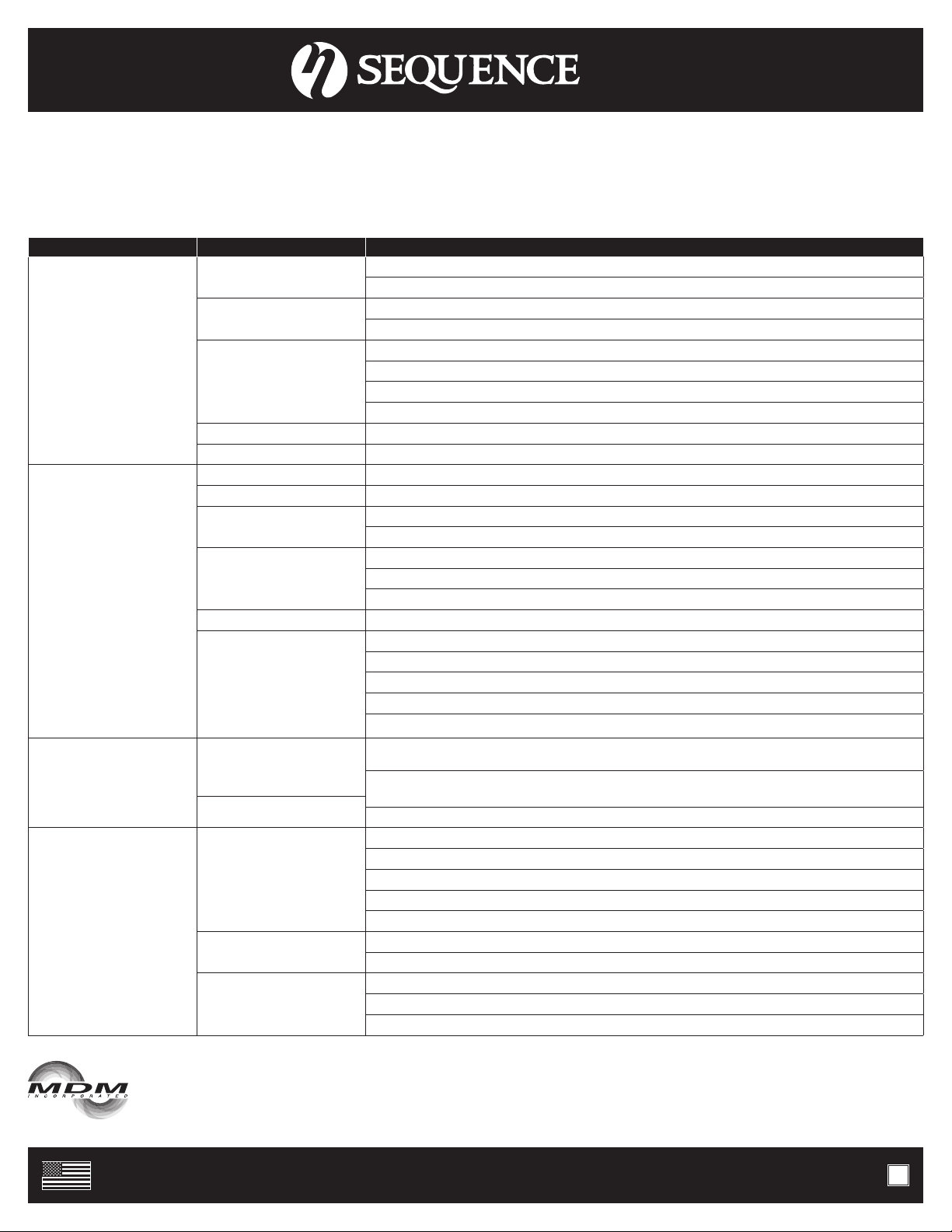
MAINTENANCE
Lubrication
Motor - Permanently Lubricated ball bearings - no service required.
Rotary Seal - Requires no lubrication after assembly.
SYMPTOM PROBLEM RESOLUTION
No Flow
Insufficient Prime Prime system with water and purge all air from suction piping.
Install check valve.
Insufficient Power Verify power supply and connection from panel to pump.
Verify proper voltage. Some models are dual voltage (115/230).
Flow Restriction
Ensure valves are open.
Ensure plumbing is clear, including suction strainers, check valves, etc.
Verify check valve orientation and direction of permitted flow.
Clean out leaves or other debris from basket strainer (if applicable).
Air leak Fix air leaks at fittings, connections, strainer basket etc. This typically occurs on the intake side.
System Incompatibility Verify hydraulic compatibility: i.e. pump and pipe are sized for the system.
Low Flow
Air leak Fix air leaks at fittings, connections, strainer basket etc. This typically occurs on the intake side.
System Incompatibility Verify hydraulic compatibility: i.e. pump and pipe are sized for the system.
Insufficient Power Verify power supply and connection from panel to pump.
Verify proper voltage. Some models are dual voltage (115/230).
Flow Restriction
Ensure valves are open.
Ensure plumbing is clear, including suction strainers, check valves, etc.
Clean out leaves or other debris from basket strainer (if applicable).
Insufficient Prime Prime system with water and purge all air from suction piping.
Cavitation
Verify airtight plumbing on the suction plumbing especially fittings.
Clean out leaves or other debris from basket strainer (if applicable).
Increase pipe size where possible.
Decrease suction pipe length, reduce the number of elbows, etc.
Verify hydraulic compatibility: i.e. pump and pipe are sized for the system.
Sporadic Operation
Insufficient Power Verify power supply and connection from panel to pump.
Verify proper voltage. Some models are dual voltage (115/230).
Poor Ventilation Ensure adequate airflow over motor to prevent overheating.
Excessive Noise
Cavitation
Verify airtight plumbing on the suction plumbing especially fittings.
Clean out leaves or other debris from basket strainer (if applicable).
Increase pipe size where possible.
Decrease suction pipe length, reduce the number of elbows, etc.
Verify hydraulic compatibility: i.e. pump and pipe are sized for the system.
Insufficient Power Verify power supply and connection from panel to pump.
Verify proper voltage. Some models are dual voltage (115/230).
Flow Restriction
Ensure valves are open.
Ensure plumbing is clear, including suction strainers, check valves, etc.
Verify check valve orientation and direction of permitted flow.
WARNING: EYE PROTECTION IS STRONGLY RECOMMENDED
*The pump must be drained before servicing or if stored below freezing
temperatures. Periodic replacement of seals may be required due to normal
carbon wear.
MDM INCORPORATED
3345 N. Cascade Ave • Colorado Springs, CO • 80907
Phone (719) 634-8202 • Fax (866) 425-1346
P.4
Gasgacinch®is a registered trademark of Porter Manufacturing.
Noryl®is a registered trademark of the General Electric Company.
Teflon®is a registered trademark of the Chemours Corporation.
Sequence®is a registered trademark of MDM Incorporated.
Sequence 750 Installation Manual 2020.indd. Adobe Indesign CC. Updated 10/12/20.