Me-Mover Speed User manual

1
ME-MOVER.COM
QUICKSTART
GUIDE
for assembly and initial ride
Me-Mover
Fitness
Speed
Designed in Copenhagen
0 - 25+ mph
0 - 35+ km/h
54.5 Lbs
23.2 kg
Foldable Front and rear
disc brakes
Ø 16”
Wheel
Variable
Transmission
S20200412
2ME-MOVER.COM
!Visit our website for more information:
https://me-mover.com
Watch the Me-Mover tutorials & tips:
Find videos on how to assemble, adjust and ride the Me-Mover.
https://youtu.be/Qexn10Gc1-4
3
ME-MOVER.COM
Congratulations on your Me-Mover Speed!
Thank you for your purchase! Here is a Quickstart Guide to get you started.
Safety notications
To highlight some of the most important safety concerns, this Quickstart Guide contains
safety warnings that are featured throughout this guide.
The following symbol WARNING! calls attention to a potential hazard that, if not
properly addressed or avoided, could cause serious injury or death, property
damage and/or void your warranty.
Me-Mover Speed is not a toy.
Children must only ride the Me-Mover Speed with adult supervision.
WARNING!
Always read the User Manual before use, as this Quickstart Guide is for your
convenience only. Please visit: https://me-mover.com
WARNING!
Any unapproved modication to the Me-Mover Speed can make it unsafe and
voids your warranty. A component that is not approved, or assembly that is not
correct can put high stress on your Me-Mover Speed or components. A frame,
fork, or component with modifications could decrease your control and cause you to
fall. Do not sand, drill, file, remove secondary retention devices, install incompatible
forks, or make other modifications. Do not remove, tighten or release any bolt(s)
connected to the structural frame, or connecting the frame to the transmissions.
Before you add an accessory to your Me-Mover FIT consult your dealer to confirm that
it is compatible and safe.
WARNING!
You must always obey your local road laws and regulations. Me-Mover is not
liable for any legal infringements. It is up to the individual rider to remain up to
date with the laws in their respective area.

4ME-MOVER.COM
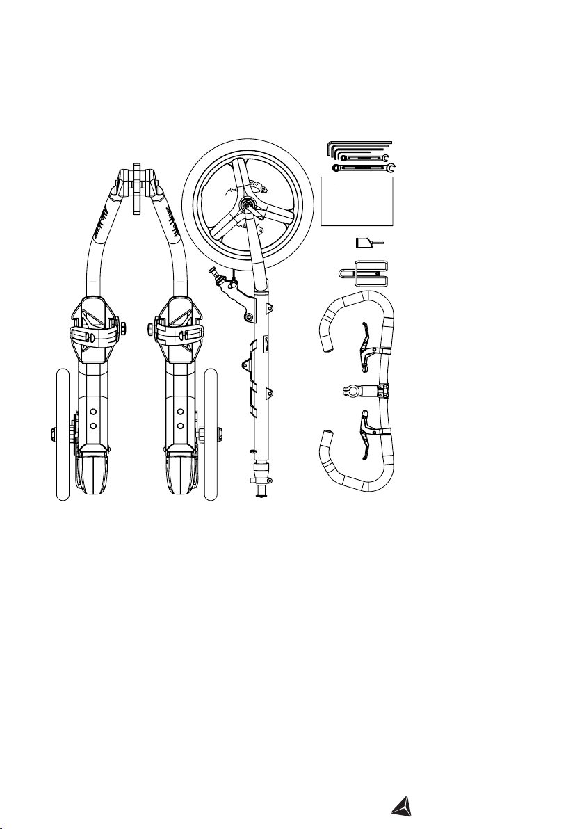
Me-Mover Speed Content Box
This is how your Me-Mover Speed is packaged in the box.
All pictures shown are for illustration purpose only. Actual product may vary due to
product enhancements.
5
ME-MOVER.COM
Frame with transmissions
and wheels
Steering column
Handlebar
Waterbottle holder
(optional)
Rear-light adaptor
Quickstart Guide
6 mm long hex-key
5 mm long hex-key
4 mm long hex-key
3 mm short hex-key
Open end 10mm wrench
Open end 13mm wrench
Quickstart Guide
The Me-Mover Speed box contains the following pieces and sub-assemblies:
6ME-MOVER.COM
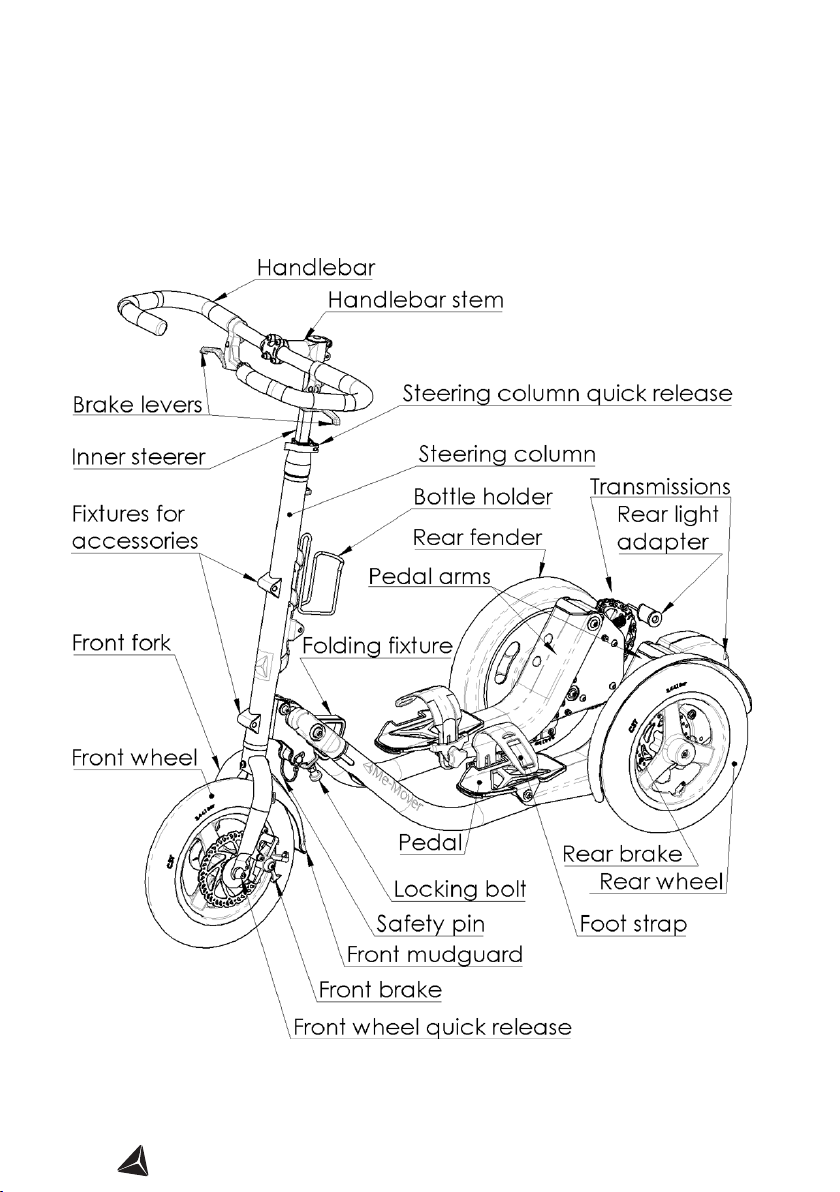
AN OVERVIEW OF YOUR ME-MOVER Speed
7
ME-MOVER.COM
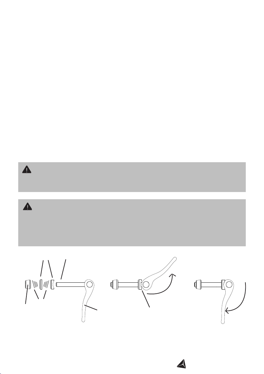
WARNING!
Always ensure that the quick releases are securely tightened suciently. If they come
loose you must re-adjust the quick release to make it tighter. Never drive the
Me-Mover Speed without having tested that your quick releases are correctly
mounted and secured.
WARNING!
To close the clamp you must use a fair amount of force, otherwise it may be too
loose.
OPEN position CLOSED position
Adjustment
screw
Washers Screw
Clamp
NOTE: When in open position, the adjustment screw needs to be adjusted so that closing
the quick release requires some force to close the clamp. The narrow part of the spring
should point towards the wheel, as illustrated.
Springs
HOW TO: USE THE QUICK RELEASES
The Me-Mover Speed has two quick releases. It is extremely important that these
quick releases are tightened securely before you use your Me-Mover Speed.
Front wheel quick release: used to secure the front wheel to the front fork.
Steering column quick release: used to adjust the height of the steering column. It can
be adjusted to suit a child or an adult.
To ensure the tightness of a quick release you need to:
1. Hold the clamp OPEN while you rotate the nut in a clockwise direction.
2. Rotate the nut until you cannot close the clamp anymore.
Then release the nut slightly so you can JUST close the clamp.
3. To close the clamp push it rmly inwards.
Grease can help to
smoothen the open/close
procedure

8ME-MOVER.COM
STEP ONE: UNBOXING THE ME-MOVER
1. Open the top layer and remove the cardboard sheet.
2. Remove now the accessory bag and handlebar.

9
ME-MOVER.COM
3. Remove the foam layer and cardboard pieces that hole the Me-Mover Speed in
place.
4. Grab the black centre part and carefully pull it up into a vertical position. Carefully lift
the product out of the box.
NOTE: The component is heavy! We urge you to use a second person to lift the object out
of the box.
5. Carefully remove the front column away from the transmissions and remove it
out of the box. We recommend to place the items on the cardboard you removed in the
beginning. Beware: Please handle the items with care. Risk of damaging the paint.
10 ME-MOVER.COM
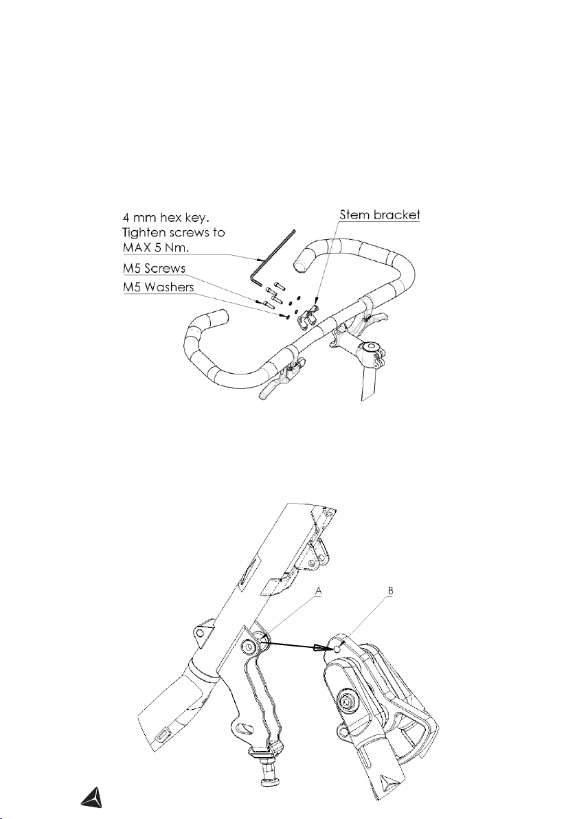
STEP TWO: HANDLEBAR AND FRONT
COLUMN ASSEMBLY
1. Mount the handlebars. Place the handlebar in the stem. Place the stem bracket in
the center and then insert the four M5 screws with the washers through the bracket into
the stem. Tighten the screws using the 4mm hex key to maximum 5Nm. Your handlebar
may already be preassembled.
STEP THREE: CONNECTING THE FRONT
AND REAR FRAME
1. Connecting the front column to the frame. Align hole A in the front column ange
with hole Bin the center block.
11
ME-MOVER.COM
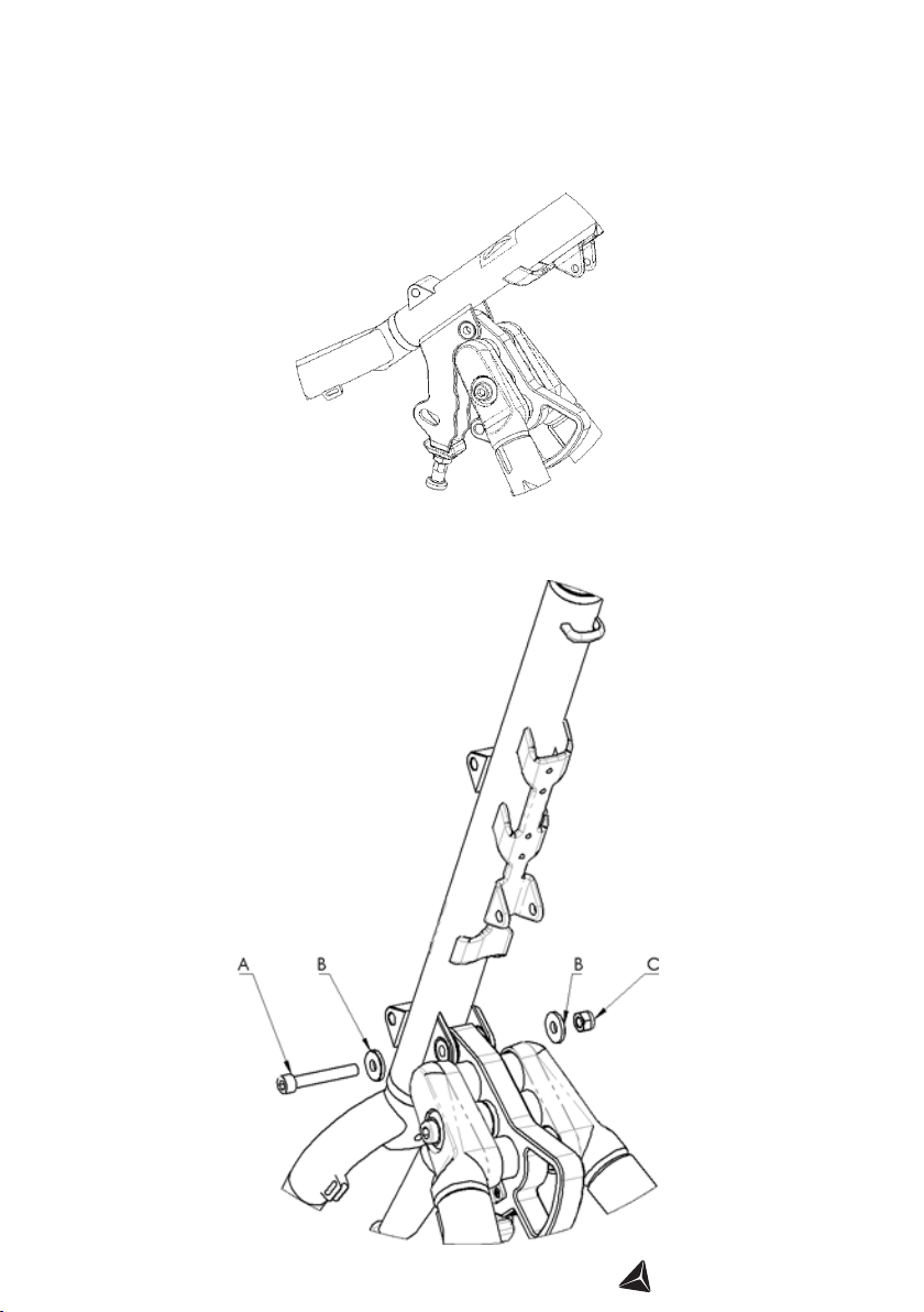
2. Connecting the front column to the frame. Front column aligned with the center
block.
3. Connecting the front column to the frame. Insert the M8 screw Awith the washer
Bfrom the left side. Place the other washer Bon the right side and mount the M8 nut C
on the right side.
12 ME-MOVER.COM
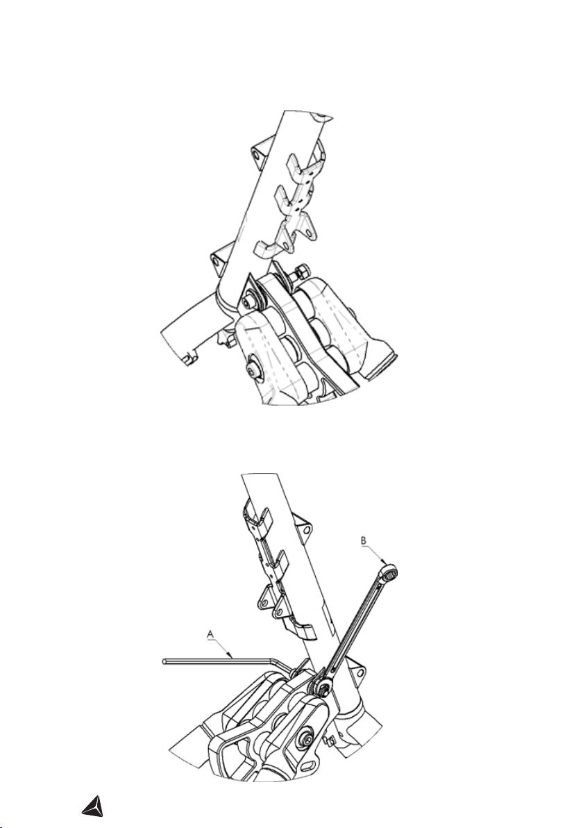
4. Connecting the front column to the frame. Front column connected with the cen-
ter block.
5. Connecting the front column to the frame. Use the 6mm hex key A and the 13mm
open wench B to tighten the screws. Tighten the screws to 15Nm.

13
ME-MOVER.COM
2. Remove the top cap. Firstly remove the dust cap. Put this somewhere safe. Then, use
the 5mm hex key anticlockwise to unscrew and remove the top cap.
Steering column
quick release OPEN
1. Mount the handlebars. Release the quick release and pull out the inner steerer. Pull
it out roughly 10cm. Whilst holding the steerer, lock the steering column quick release in
place.
Important: The quick release needs to
be locked rmly to avoid loosing the inner
steerer into the front column!
STEP FOUR: MOUNTING THE HANDLEBARS
Steering column
quick release CLOSED
Inner steerer
Top cap
Dust cap
14 ME-MOVER.COM
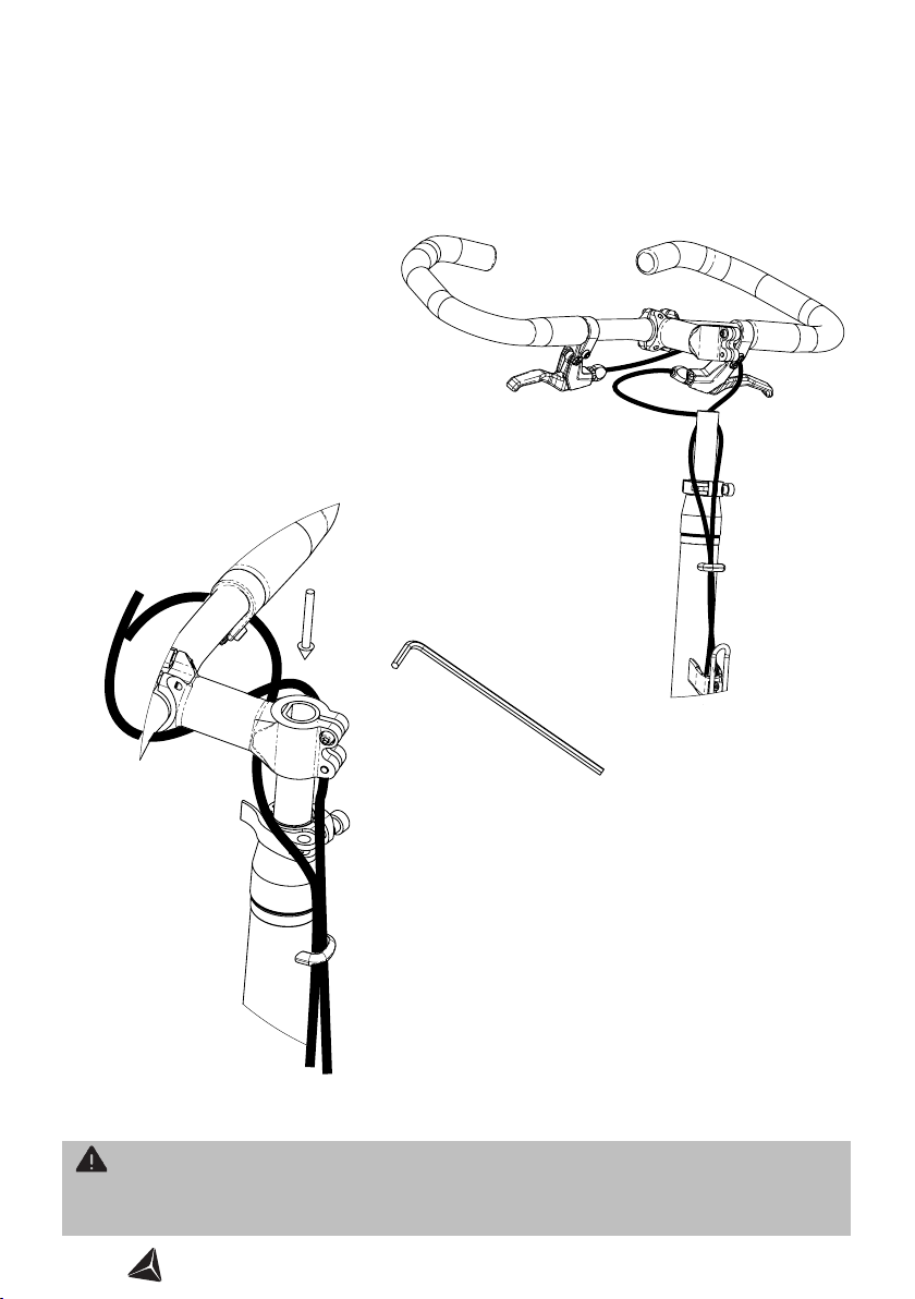
3. You are now ready to mount the bars on the steering column! Firstly, ensure
the brake cables are threaded correctly as illustrated. The cables should be thread-
ed behind the bottle holder, through the cable loop on the steering column, and then
around the inner steerer below the stem as shown below.
4. Insert the stem onto the steerer. Make it
ush with the top of the steerer. Use the 4mm
hex key to tighten the screws. Do not over tighten.
Tighten to a no more than 5Nm.
WARNING!
Do not tighten the screws with more than 5Nm. 5Nm corresponds to a 20cm long
wrench with a force of 2.5kg.
NOTE: Lubricate the inner steerer with oil or grease.
NOTE: The left brake cable loops under
the stem from the left hand side. The
right brake cable loops under the stem
from the right hand side. This ensures
the cables are close to the frame; not
interfering with the riders knees whilst
riding.

15
ME-MOVER.COM
STEP FIVE: MOUNTING THE BRAKE CABLES
1. Fitting the brake cables. The cables should be threaded behind the bottle holder,
through the cable loop on the steering column, and then around the inner steerer below
the stem as shown below.
NOTE: The left brake cable loops under the stem from the left hand side. The right brake
cable loops under the stem from the right hand side. This ensures the cables are close to
the frame; not interfering with the riders knees whilst riding.

16 ME-MOVER.COM
2. Final checks: The handlebar should look like below. Remember, if the cables are not
organised correctly they may get in the way when riding.
NOTE: The left brake cable loops under the stem from the left hand side. The right brake
cable loops under the stem from the right hand side. This ensures the cables are close to
the frame; not interfering with the riders knees whilst riding.
Cable loop
LR
Inner steerer
Stem
WARNING!
Make sure that the front cable is not twisted before you drive your Me-Mover. The
cable may twist if you accidently turn the handlebar by 360 degrees.
17
ME-MOVER.COM
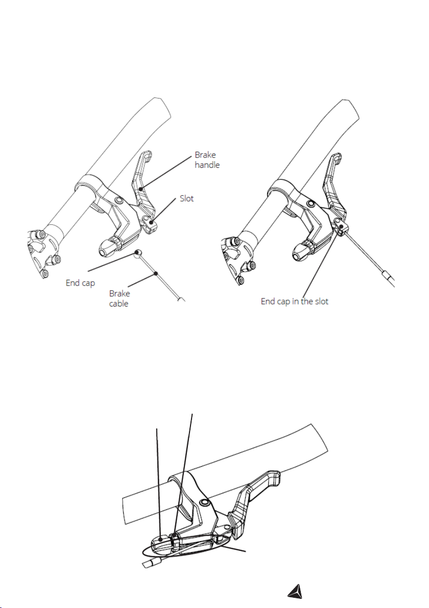
3. Connect the brake cables with the brake levers. Pull the brake handle and insert
the end cap into the slot in the brake handle.
4. Align the lock nut and adjustment screw and slide the cable into the groove. If
necessary, pull the brake cable housing so more cable is exposed. Screw the lock nut and
adjustment screw tight.
NOTE: Please take note of which cable operates the front and the rear brake when doing
this step. There may be local laws regulating how your brakes need to function.
Lock nut
Adjustment
screw
Groove
18 ME-MOVER.COM
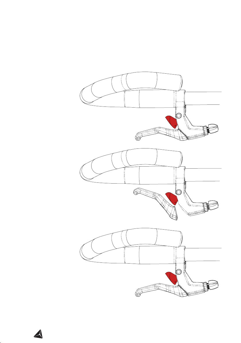
2. whilst keeping pressure on the red lever, pull the brake lever. Until you hear a click.
HOW TO: ENGAGE THE PARKING BRAKE
2. Whilst keeping light pressure on the red lever,
pull the brake lever until you hear a click.
1. Put light pressure on the red lever.
3. Maintain light pressure on the red lever.
Release the brake lever. The parking brake will
now be engaged.
CLICK!
In order to disengage, just pull the brake lever. You do not need to touch the red lever.
The brake lever may or may not
have the parking brake feature.
Subject to availability.

19
ME-MOVER.COM
A
.
Don’t forget to re-insert the
safety pin. Do not ride the
Me-Mover without the safety
pin.
Engage the front brake whilst pushing forward on the handlebar. You should hear a click.
This click is important to ensure safe riding.
CLICK!
WARNING!
If you do not hear the ‘CLICK’ sound it means the locking bolt has not been secured in
place. If the locking bolt does not click into place, do not use the Me-Mover Speed
under any circumstance. There should be no space around the locking bolt. Remem-
ber to re-insert the safety pin.
HOW TO: UNFOLD YOUR ME-MOVER Speed
1. Remove the safety pin: Open the safety clip Aby releasing the spring with your
thumb. Remove the pin.
20 ME-MOVER.COM
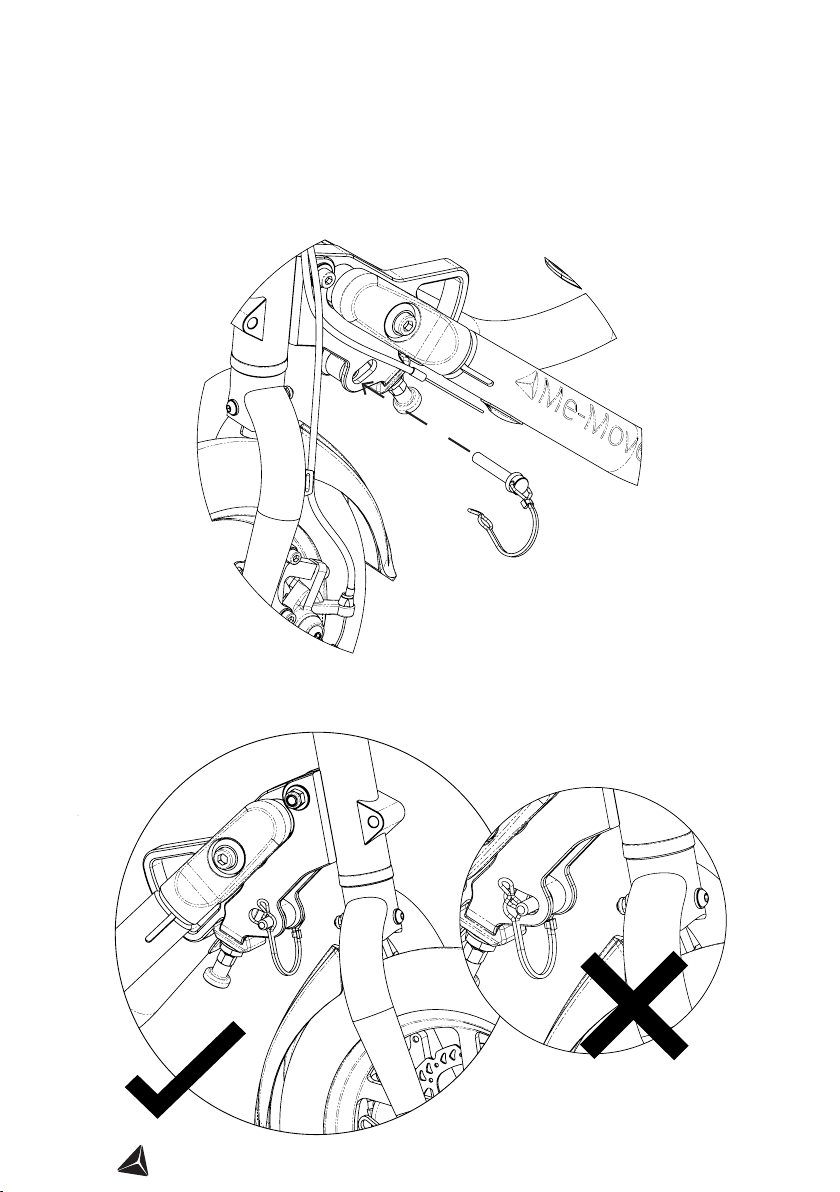
HOW TO: FIT THE SAFETY PIN
NOTE: When tting the safety pin, ensure the attached wire loops around the pin as
shown below. Do not ride the Me-Mover Speed without correctly tting the safety pin.
NOTE: Ensure the attached wire loops around the pin as shown below. Do not ride the
Me-Mover Speed without correctly tting the safety pin.
This manual suits for next models
1
Table of contents
Other Me-Mover Bicycle manuals


 owner's manual")


