Measurement Systems International MSI9850 User manual

MSI9850
RF Remote Weight Indicator
Operator’s Manual

Page 2 MSI-9850 RF Remote Indicator • User GuideMSI-9850HANDHELDRFREMOTEINDICATORforCELLSCALE®TABLEOFCONTENTSSECTION 1 – INTRODUCTION & ORIENTATION ................................4
Introduction .........................................................................4
MSI-9850 Front Panel .........................................................4
Key Descriptions .................................................................4
9850 Display Symbols ........................................................6
General Information ............................................................7
Manual & 9850 Conventions ..............................................7
Features ...............................................................................8
9850 Block Diagram ...........................................................8
The CellScale Family ........................................................9
Unit Setup .........................................................................10
Battery ...............................................................................10
9850 Connectors & Wiring ...............................................11
Main Power Input ..............................................................12
Aux Power and Switches ..................................................13
Serial Ports ........................................................................14
Set Points Output ..............................................................15
Antennas ............................................................................19
Standard Antenna ..............................................................20
Long Range OMNI 9dBi Antenna w/ Pipe Mount ...........20
YAGI Antenna ...................................................................21
Corner Reflector Antennas ................................................21
Vehicle Mount Whip Antenna ...........................................21
Standard antenna bulkhead extensions .............................22
Other Antennas ..................................................................22
2.4 GHZ Interference ........................................................22
FCC’s MPE Requirements ................................................22
SECTION 2 – RF SCALE COMMUNICATIONS ..................................23
FCC Statement ..................................................................23
Network Description .........................................................23
RF Network Setup .............................................................24
Advanced Modem Settings ...............................................25
Configuring for multiple networks ....................................26
Troubleshooting RF Connection Problems .......................27
RF Site Testing ..................................................................28
CellScale Network Auto Scan ...........................................28
SECTION 3 – SCALE OPERATION .................................................29
Power ...............................................................................29
Multiple Scale Channels ...................................................29
Selecting The Active Channel ...........................................29
Multi-Channel Systems .....................................................30
To Select The Display Channel .........................................30
Zero ...................................................................................31
Tare ....................................................................................32
Setup Tare Menu ...............................................................33
Net / Gross ........................................................................34
Units ..................................................................................34
Peak Hold (Function Key Option) ....................................34
Send / Print ........................................................................34
Display Test .......................................................................35
SECTION 4 – FUNCTION KEYS ....................................................36
Setup Function Keys .........................................................36
Default Function Keys ......................................................37
Default ENTER-Function Keys ........................................37
Default External (p2) Switches .........................................37
Default RF Remote Keys ..................................................37
Default RF Remote Keys ..................................................37
Available F-Key & Switch Functions ...............................38
Custom Function Key Labels ............................................41
SECTION 5 – RF REMOTE CONTROL OPTION ...............................42
Description ........................................................................42
Functions ...........................................................................42
Setting the Transmitter Address ........................................42
Contention Considerations ................................................43
Battery Replacement .........................................................43
RF Remote Control FCC Statement ..................................43

MSI CellScale® System • 9850 User Guide Page 3
MEASUREMENTSYSTEMSINTERNATIONAL
Firmware Version 5-XX for 2450 Modems
SECTION 6 – ID CODES ..............................................................44
ID Code Organization .......................................................44
Setup ID Codes Menu .......................................................45
Using ID Codes .................................................................46
ID Code String 1 & String 2 .............................................47
SECTION 7 – TOTAL / STATISTICS ................................................48
Total ...................................................................................48
Auto Total ..........................................................................48
Setup Total Menu ..............................................................49
View Total .........................................................................50
Statistics ...........................................................................51
SECTION 8 – 9850 SETUP ..........................................................53
System Setup Menu ..........................................................53
Password Locks .................................................................54
Keyboard Lock ..................................................................55
LC Display Backlight & Contrast .....................................55
Standard & Custom Display Setup ...................................56
Scale Display Setup Menu – Preset Displays ...................59
Using Display Setup ..........................................................60
Custom Display Setup .......................................................61
Custom Screen Setup Procedure .......................................64
Custom Single Channel Display Setup Menu ...................65
Custom Multi-Channel Display Setup Menu ....................66
SECTION 9 – SET POINTS ...........................................................67
Introduction .......................................................................67
Set Point Setup Menu ........................................................68
Program Set Point Menu ...................................................69
9850 Response Menu ........................................................70
Set Point Formula Menu ...................................................71
SECTION 10 – COMMUNICATION PORTS .......................................72
Introduction .......................................................................72
Electrical Conformance .....................................................72
Mating Cable .....................................................................72
Data Configuration ............................................................72
Trigger Print ......................................................................72
Comm Port SeLECT Menu ...............................................73
Comm Port Setup Menu ....................................................73
General Text Entry ............................................................75
General Text Entry Menu ..................................................76
Printer / Output Formatting ...............................................77
Example Printer Formatting ..............................................77
Programming the End of Line or Start of Line Strings .....78
Editing the Print String .....................................................78
General Text / Control Character Entry ...........................82
Serial Output “@” Commands ..........................................83
SECTION 11 – DATA LOGGING ....................................................84
Introduction .......................................................................84
Data Logging Setup ..........................................................84
Data Logging Control Menu .............................................84
SECTION 12 – TEXT MESSAGING ................................................86
Host Message Design ........................................................86
9850 to Host Messages .....................................................87
SECTION 13 – BAR CODE ..........................................................88
Bar Code Setup Menu .......................................................88
SECTION 14 – CHANNEL SETUP & CALIBRATION .........................90
Channel Setup Menu .........................................................90
Calibrate General Information ..........................................91
Enable Calibration .............................................................91
To Calibrate ......................................................................91
To Enable / Disable AZM (Auto Zero Maintenance) ........93
Motion Band .....................................................................93
Center-of-Zero (COZ) Indicator .......................................94
Reset All ............................................................................94
Installing Firmware Updates .............................................95
9850 Setup Duplicating .....................................................97
APPENDIX A – MENU MAPS ......................................................98
Setup Select Menu ............................................................98
Total Settings .....................................................................98
Password Locks .................................................................98
Function Keys ...................................................................99
Serial & Strings ...............................................................100
Product ID Codes ............................................................101
Bar Code Setup ...............................................................101
Tare Settings ....................................................................102
RF Modem Settings ........................................................102
Scale Display Setup ........................................................103
Scale Single Channel Custom Display Setup .................104
Scale Multi-Channel Custom Display Setup ..................105
Channel / Calibrate Settings ...........................................106
System Settings ...............................................................107
Display Test .....................................................................107
Monitor Batteries ............................................................107
Calibration .......................................................................108
Reset All or Reset RF Modem ........................................108
General Text Entry ..........................................................109
Set Points .........................................................................110
APPENDIX B – ASCII CHART ..................................................111
APPENDIX C – SPECIFICATIONS & SUMMARY OF FEATURES ........112
THE MSI LIMITED WARRANTY ................................................113

Page 4 MSI-9850 RF Remote Indicator • User GuideMSI-9850HANDHELDRFREMOTEINDICATORforCELLSCALE®KEYDESCRIPTIONSSECTION1–INTRODUCTION&ORIENTATIONINTRODUCTIONThe Measurement Systems International MSI-9850 RF Remote Indicator is an accessory component of MSI's
CellScale® System. Combined with 1 or more CellScales, the 9850 provides complete control over all scale and
data functions. The 9850 serves as a remote terminal for any CellScale and has no internal measurement capabil-
ity. One 9850 can read the output of many CellScales, and 1 CellScale can also provide data to many 9850's. The
backlit, alphanumeric graphic display provides precise, unambiguous indication of operating modes such as Net,
Gross, or Total. The 9850 can calibrate a CellScale remotely and provides a user interface to the advanced features
of the CellScale. The CellScale system is digitally calibrated from either the 3750CS Indicator, the MSI-9850
Advanced Indicator, a 9850 Indicator, or with a terminal program hooked directly to the CellScale model 9000.
The 9850 combined with a CellScale is designed to meet or exceed the requirements of all regulatory agencies.
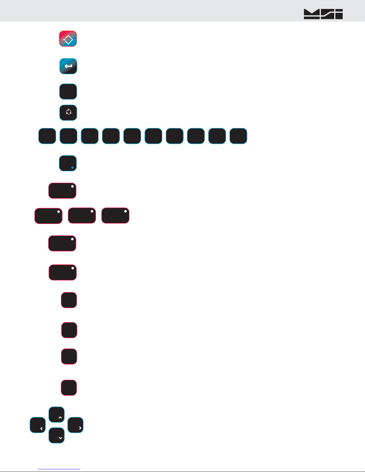
MSI-9850FRONTPANEL
POWER
ZERO0
TARET
NET/GROSSB/G
The POWERkey turns the 9850 On and Off. The POWERkey must be held for 1 second to ensure startup.
The ZEROkey is used to zero out residual weight on the scale.
The TARE key is used to zero out the weight of containers, trucks, or carriers and to place the scale in the Net weight
mode.
The NET/GROSS key allows the operator to alternate the weight display from Net (Tared) weight to Gross weight. In
some Legal-for-trade jurisdictions, the Gross weight display is limited to 3 seconds.
9850
MeasurementSystemsInternational
Seattle,WashingtonU.S.A.
TAREZEROSETUPNET/GROSSABCDEFGHIPQRESC!TB/G0Aa1SPACEEXITSTUVWX@YZMNOJKLPOWERIDCHANNELCLEARENTERF7F8F9F10DATA 1DATA 2DATA 3RF ADDRSEND / PRINTTOTAL VIEW TOTAL DISPLAY
F1F2F3F4F5F6 LO BATTAW502433RevA.2/2/2005FH10
Six User Programmable Illuminated Function Keys6 Digit 1.2” High Bright-ness LED Display8 Line x 21 Character Information Display4 User Progammable Function KeysCursor KeysScale Control KeysData Entry Alpha-numeric KeypadDownloaded from www.Manualslib.com manuals search engine
MSI CellScale® System • 9850 User Guide Page 5
MEASUREMENTSYSTEMSINTERNATIONAL
Firmware Version 5-XX for 2450 Modems
SETUPESC!
ENTER
Aa1
9
@YZ6
PQR3
GHI2
DEF5
MNO8
VWX0
SPACE7
STU4
JKL1
ABC
F10 DISPLAY
F8TOTAL
CHANNELF7
SEND / PRINTF6
RF ADDRF5
F9 VIEW TOTAL
IDF1
DATA 1F2
The SETUPkey allows entry into the setup submenus. Use this to find menus for setting the Date and Time, setting up
the function keys, controlling the display mode and backlight, password locks, calibration, etc.. The key is also used for
ESCape. Use ESC to return to the previous menu, or display mode.
The ENTER key finalizes the entry of numeric or alphanumeric text entries. It also provides an alternate way to maneu-
ver through menus combined with the cursor keys. Pressing ENTER before certain keys takes you directly into various
modes. Pressing ENTER before a Function key enacts the alternate Function key mode.
The ALPHAkey is used during text entries to select upper case, lower case or numbers. Also used for negative number
entry in numeric entry screens.
The numeric keypad provides all numerals
and letters for data entry. Submenus pro-
vide punctuation and control characters.
DATA 2F3
DATA 3F4
F1 defaults to NEXTID. Pressing F1will change you to the next defined ID. Any data field or 9850 function can be
assigned to this key. The blue light will illuminate when the button is pressed to indicate the 9850 is waiting for Data
(when the key is assigned a Data field type).
F2, F3, and F4 are for user defined Data entry. Any data field or 9850 function can be assigned to
these keys. When these keys are programmed for Data entry, the blue light will illuminate when
the button is pressed indicating the 9850 is waiting for data. These default to Get Barcode 1-3.
F5 defaults to RFADDRESS. The RFADDRESSkey is used to log on to other CellScale Networks. Pressing the
ADDRESSkey alone will change the active network to the next defined Network. Preceding the RFADDRESSkey
with a Network number (0-63) will cause the 9850 to log directly on the entered Network, if it exists and is active. If
changing the network is not necessary, any data field or 9850 function can be assigned to this key.
F6 defaults to SEND/PRINTALL. The action of this key is dictated by the Function key menu, but is usually used to send
data to the CellScale or one of its hosts. If the Send/Print function is not necessary, any data field or 9850 function can be
assigned to this key. The blue light will illuminate until the Send/Print function is completed and acknowledged.
F7 defaults to NEXTCHANNEL. When the CellScale has more than 1 channel defined in its Scan List, the F7key
will select the next active channel in the list. Precede the NEXTCHANNELkey with a numeric entry (1-32) to switch
directly to a channel scan list position. Press SETUP-CHANNEL for a shortcut to the “Channel Setup Menu”. If chang-
ing the channel is not necessary (as in single channel scale systems), any data field or 9850 function can be assigned to
this key.
F8 defaults to TOTAL. Pressing this key will cause the current weighment to be added to the total register (Manual Total
mode). In Auto-Total modes, the TOTALkey turns Auto-total off and on. If the Total function is not necessary, any data
field or 9850 function can be assigned to this key.
F9 defaults to VIEWTOTAL. When pressed the information display will show the Totals screen with links to the statistics
and grand total screens. Press VIEW TOTAL again to return to the previous screen. LFT 9850’s default F9 to the UNITS
function. Pressing this key will change the operational units (if enabled) of the current focus channel. If the View Total
function is not necessary, any data field or 9850 function can be assigned to this key.
F10 defaults to DISPLAY. The DISPLAYkey is used to alternate between single channel displays and multiple chan-
nel displays. While in the multiple channel display, highlight the desired channel using the UP/DOWN Cursor keys,
then press DISPLAY to bring up the single channel display. This selected channel is the “Active” or “Focus” channel to
which all subsequent actions will be applied. Provides the overwrite cursor (the cursor defaults to insert mode) function
in text and data entry screens.
The Cursor keys are used to select the active channel while in multiple display modes. The active channel is displayed
on the LED display. While in setup menus, the cursor keys are used to navigate menu choices and to control the text
editing cursor.
CLEARC
The CLEARkey is used for deleting entries and editing. In data entry screens, pressing CLEAR deletes the character
in front of the blinking cursor.
EXIT
The Decimal Point key is used in numeric entries. The EXIT function is used to exit out of setup screens. EXIT will cause
the 9850 to exit out of all levels of menus and return the LCD to the last weight display. This differs from the ESC key
which just backs you up one menu level.
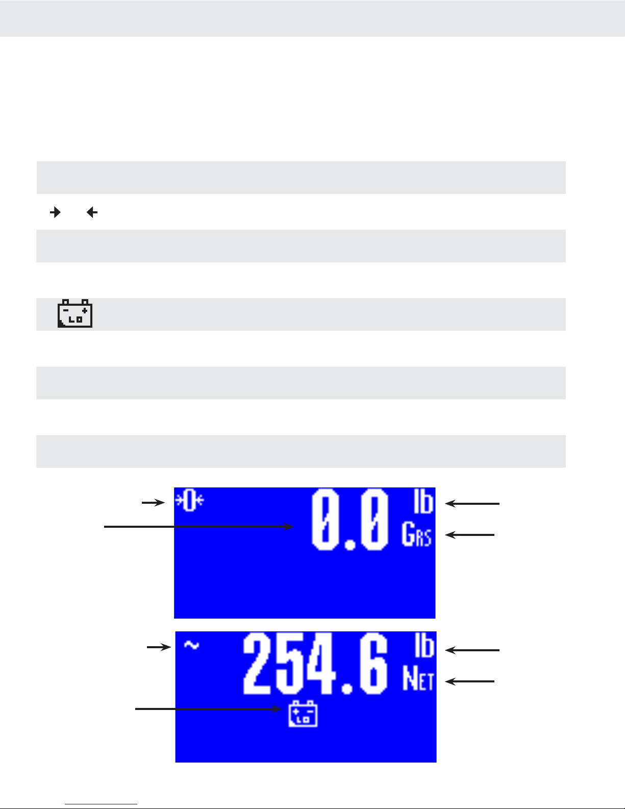
Page 6 MSI-9850 RF Remote Indicator • User GuideMSI-9850HANDHELDRFREMOTEINDICATORforCELLSCALE®9850DISPLAYSYMBOLSThe 9850 uses a full dot matrix graphics display which allows 3 sizes of fonts and full use of graphic symbols.
On standard single channel and multi-channel displays, certain symbols are used for scale specific indications.
The motion symbol indicates that the weight has not settled within the motion window (usually ±1d). While this
symbol is illuminated, the scale will not zero, tare, or totalize.
Center-of-Zero – Indicates the weight is within 1/4d of zero. In the small font it appears as “>0<”.
The Sigma symbol is used to indicate a total weight
GRS – Abbreviation for Gross Weight
Low Battery Symbol – Appears when approximately 10% of battery life remains. The 9850 places the indicator
in various locations depending on the display mode
ton– Indicates US short tons equal to 2000 lb.
tne – Indicates metric tons equal to 1000 kg.
daN – Indicates the force measurement unit dekaNewtons.
Dashes indicate data not yet received from the CellScale, or the RF network is disconnected.
O~∑
GRStontnedaNCenter of Zero Indicator
Weight Display
Scale in Motion Indicator
Low Battery Indicator
Units Indicator
Weight Mode
(Gross, Net, Tare)
Units Indicator
Weight Mode
(Gross, Net, Tare)
------––TypicalLCDweightdisplaysshowingtheuseofcommonsymbolsDownloaded from www.Manualslib.com manuals search engine

MSI CellScale® System • 9850 User Guide Page 7
MEASUREMENTSYSTEMSINTERNATIONAL
Firmware Version 5-XX for 2450 Modems
GENERALINFORMATIONThe 9850 is a versatile indicator capable of displaying many data items. As a member of the CellScale family the
9850 does not stand alone. It is a slave device to a MSI-9000 CellScale. All data displayed on the 9850 is received
via RF from a master CellScale. Many menus in the 9850 depend on information from the CellScale. Therefore,
turn the CellScale on before using the 9850.
Due to the high data rates in the CellScale system menus usually respond instantly. However there are times
when the CellScale is busy and it will not “service” the 9850 instantly in all circumstances. At these times you
may see the word “Pending” or dashes, or data placeholders which will indicate the CellScale has not yet sent
the required information. Weight displays have priority and are sent before all text strings are updated (such as
channel name, ID name, etc.).
The majority of CellScale installations have only a single scale input. In this case the Multiple Display modes
are not needed. However, even with only a single scale input, Math Channels are available which can be applied
for specialized applications.
MANUAL&9850CONVENTIONS 1) Keys used in operations are printed in BLUEand capitalized. Numeric keys are bracketed (e.g. [5]).
2) Setup procedures are usually shown with the shortcut method of reaching the menu. All menus can also be
reached through the “Setup Select Menu”. Use the[7] key to see all available menu choices.
3) Screen shots are shown for example. Many screens provide additional information to orient the user to the
scale channel, or ID, or selections made. For example, the Function Key Setup menu will show you the current
selection for each key. When you change the function, the previous menu changes to reflect your choice.
4) If a function key does not work, it is probably because the CellScale is not setup to support the key. For
example, if only one channel is defined in the CellScale, pressing the CHANNELkey will have no effect.
This also applies to the RFADDRESSkey. If only one Network has been defined, the RFADDRESSkey
has no other Network to log onto.
5) Menu Titles are shown at the top of the LCD screen and are fully capitalized.
6) When space permits, selected parameters are shown at the right side fully capitalized.
7) Submenus with multiple choices use a highlighted arrow “4” to indicate current choice(s). Multiple choice
menus require the ENTER key to save changes.
8) When in menus, the ESCkey drops back one menu level.
9) When in Setup Menus, the EXITkey returns you directly to the Weight Display (Exit mode).
10) Cursor Keys function in menus and in multi-channel display modes. Use the DOWN (v) cursor key to enable
the cursors then use the UP (^) or DOWN (v) cursor to select line items or change the focus channel in the
multi-channel weight display mode. Channel selection using the cursor keys also picks the channel that is
copied to the large LED Weight display. When in setup menus, use ENTER, LEFT (<), or RIGHT (>) cursor
keys to rotate through menu choices or select the associated submenu.
11) If a submenu is associated with a menu choice, either highlight the menu choice with the cursor keys and
press ENTER, or press the numbered key corresponding to the desired menu item.
12) If a menu applies to any channel, pressing the CHANNELkey will select the next channel in the CellScale’s
scan list.
13) If a menu applies to any ID, pressing the IDkey will select the next ID in the CellScale’s ID list.
14) To input, for example, an ‘E’, first use the ALPHAkey to change to alpha mode, then press [2]twice. If you
need two ‘E’s, pause briefly until the display cursor has moved to the next position, then press [2] twice.
15) In single display modes, pressing the ENTERkey highlights the whole LC Display to indicate the next press
of a Function key will use the alternate mode (Enter-Function Key).
16) From any weight mode, press the ENTER key twice to display the current Function Key, Enter- Function
Key, External Switch, and RF Remote Control Switch assignments. Press ENTER to see each screen. Press
ESC to return to the previous display or wait 20 seconds for the display to return to the previous weight
display.

Page 8 MSI-9850 RF Remote Indicator • User GuideMSI-9850HANDHELDRFREMOTEINDICATORforCELLSCALE®FEATURES• Designed to meet or exceed all US and international standards.
• Multiple Customized Display Modes, single channel or multiple channel modes
• Reliable 2.4 GHz Frequency Hopping RF communications. Highly immune to interference and multi-path
problems. Range in excess of 500 feet indoors (LOS).
• Each 9850 can act as a terminal for any CellScale. A 9850 can monitor multiple scale channels on a single
CellScale, or multiple scales tied to multiple CellScales.
• Store up to 32 per connected CellScale ID Codes with separate Alphanumeric Names, Tare, Mode, and Totals.
ID Codes are addressed by any customer given name or number. Two user entered ID data strings are available
for each ID code. Support for up to four Bar Code entry strings.
• Easy to read annunciation of ID Names and Menu Prompts are provided on the fully customer defined display
screen.
• Full RS-232 output formatting offers exceptionally versatile data output. Weight data can be printed in any
desired way. The customer can add any alpha characters and/or printer formatting commands; including for-
matting for Bar Code printers. Bar Code readers can also be attached to the Comm Port.
• Manual or Automatic Data Logging into battery backed memory. Any data can be stored for later downloading
into a computer.
• Display illumination uses rugged, long life, LED backlighting coupled with a transflective LCD to provide
optimum display contrast under all ambient conditions from full sunlight to total darkness. When the 9850 is
powered by batteries, the backlight automatically turns off and on when needed to conserve battery life.
• Selectable for lb., kg, g, tons, metric tons, ounces, and daN for force measurement (some units and /or units
switching may be prohibited in legal for trade units).
• Multi-mode automatic or manual weight totalizing with multiple ID registers.
• Weather resistant sealing ensures reliable operations under harsh conditions. Rugged, gasketed, Marine Grade
Aluminum Enclosure is rated to IP67.
9850BLOCKDIAGRAMDownloaded from www.Manualslib.com manuals search engine
MSI CellScale® System • 9850 User Guide Page 9
MEASUREMENTSYSTEMSINTERNATIONAL
Firmware Version 5-XX for 2450 Modems
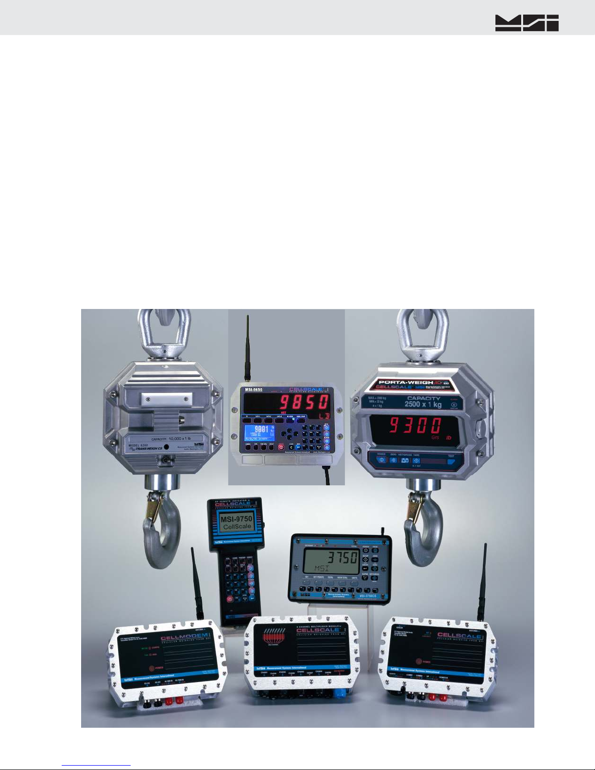
THECELLSCALEFAMILY1) Model MSI-9000 CellScale – Rugged unit for interfacing any scale and converting it to RF networking.
2) Model MSI-9008 Multiplexer – Allows up to eight scales with independent calibrations, to share a single
CellScale input channel.
3) Model MSI-9020 CellModem – For interfacing peripheral devices to a CellScale.
4) Model MSI-3750CS – Fixed mount indicator for CellScales. Capable of control and calibration.
5) Model MSI-9850 – Portable remote indicator for CellScales. Capable of control and calibration. Can display
multiple channels.
6) Model MSI-9300 – CellScale based Crane Scale with local LED display.
7) Model MSI-6260CS – CellScale based Crane Scale. Available in standard capacities up to 100000 lb (50000
kg) and by special order up to 250 tons
8) Model MSI-9850 – Advanced Capability Fixed mount Remote Indicator.
Model MSI-9260 – (Not pictured) Motion Compensated Crane Scale used in scrap metal weighing.
Model MSI-9002 Summing Box – (Not pictured) Single or Dual Channel summing of up to 4 load cells.
Model MSI-9300HT – (Not pictured) High Torque version of the MSI-9300 for fixed hook, rotating load
applications.
1
23
4
5
6
78

Page 10 MSI-9850 RF Remote Indicator • User GuideMSI-9850HANDHELDRFREMOTEINDICATORforCELLSCALE®UNITSETUPThe 9850 is simple to setup and use. If there are no peripheral devices such as a printer or bar code scanner, setup
consists of applying power, and setting the modem controls to talk to a 9000 CellScale.
BATTERYFuture Option - Contact MSI for information
MSI CellScale® System • 9850 User Guide Page 11
MEASUREMENTSYSTEMSINTERNATIONAL
Firmware Version 5-XX for 2450 Modems
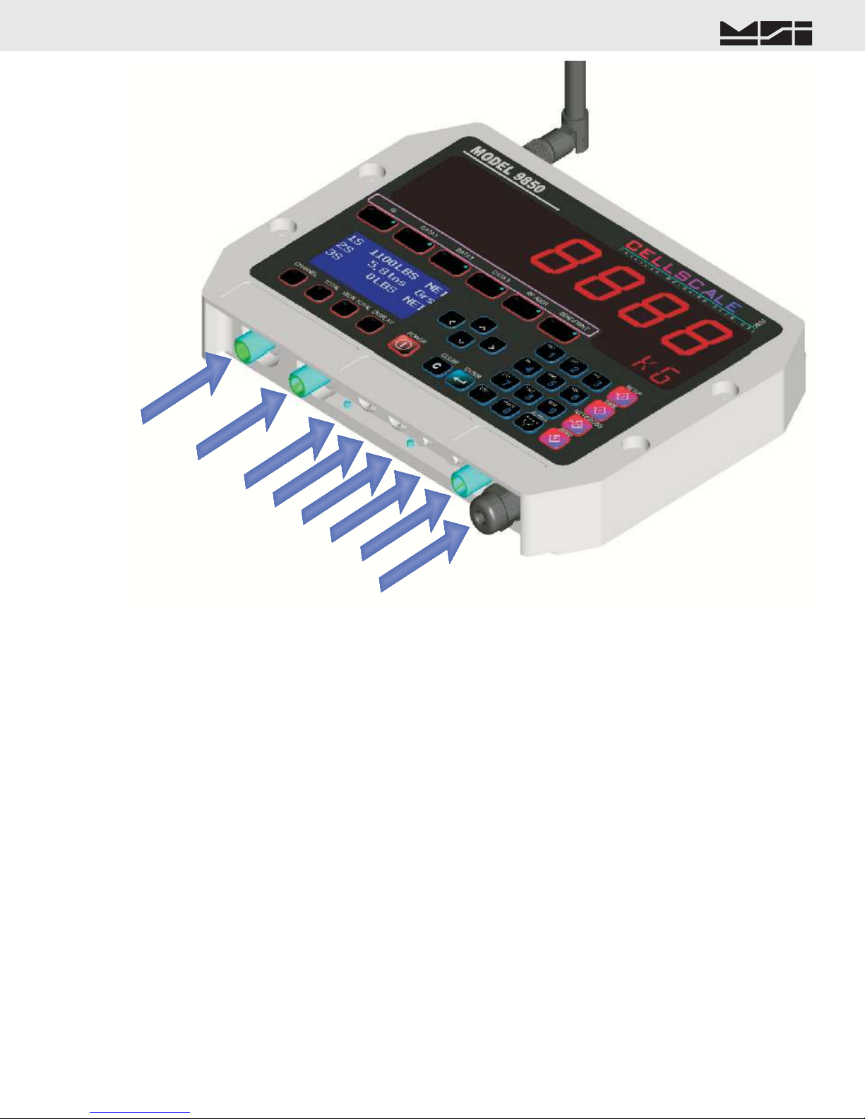
Power Input
AUX3
AUX1
AUX2
Aux Pwr + Switches
Set Points Output
Comm Port 2
Comm Port 1
P2
P3
P4
P5
9850CONNECTORS&WIRINGThe standard configuration of the 9850 has the following connectors:
1) Main Power Input – Usually a heavy duty cable for power input. Available also with a connector by special
order. AC and DC power modules are available for all industrial voltage sources.
2) Aux Power and Switches (P2) – Provides a means to attach external user programmable switches for foot-
switches, joy stick mounted switches, etc. The Auxiliary Power input can be used for battery backup to ensure
continuous operation. Recommended Power Source is a 12V Sealed Lead Acid Battery.
3) Set Points Output (P3) – Provides a relay driver for up to 5 external relays, lamps, or alarms.
4) Comm Port 2 (P4) – RS-232 Serial I/O.
5) Comm Port 1 (P3) – RS-232/422/485 Serial I/O with programable termination.
6) Antenna – Standard TNC Coaxial. Fits all MSI Antenna Options. In outdoor or washdown applications, the
antenna connector must be sealed with adhesive heat shrink to ensure sealing.
Accessory Connectors AUX1, AUX2, and AUX3 are for system expansion. If not occupied, the mounting holes
are covered with a seal plate.
Contact MSI for information on available and planned expansion option modules.

Page 12 MSI-9850 RF Remote Indicator • User GuideMSI-9850HANDHELDRFREMOTEINDICATORforCELLSCALE®MAINPOWERINPUTThe 9850 is powered by AC or three choices of DC inputs.
Universal AC Supply
The universal AC Supply is suitable for mains inputs from 86 to 265VAC, 47-440 Hz. The 9850 can be ordered
with a standard US Cord (NEMA 5-15 Plug) or an unterminated AC Cord for direct panel wiring or adding a
country specific AC Plug. Always connect the ground wire (Green or Green/Yellow Stripe) to an Earth Ground.
The 9850 Chassis is connected to earth ground.
Color Code, International Cord:
Brown Connect to Hot (L)
Blue Connect to Neutral (N)
Green/Yellow Stripe Connect to Earth Ground
Color Code, US Cord (SJOOW):
Black Connect to Hot (L)
White Connect to Neutral (N)
Green Connect to Earth Ground
The universal AC Supply can also be used for High Voltage DC inputs. In this mode it is rated from 120VDC to
370VDC. The ground wire must be connected to earth ground. When connecting to high voltage DC sources, MSI
suggests a line conditioner to filter large spikes generated by motors and contactors. Use the Hot wire to connect
to the positive high voltage terminal. Use the Neutral wire for the DC return.
For installations that might have intermittant power interuptions (such as bridge cranes), we suggest a battery is
connected to the Aux Power input to provide uninterrutible power. The battery should output less voltage than the
main supply, so that it will not drain in normal use. With the internal AC supply (15V), a 12V Sealed Lead Acid
is a good choice. However, the Aux Power input will take over when the main power is shut down, so the user
must turn off the 9850 (or use the auto power down modes) to prevent discharging the backup battery.
The9850ContainsHazardousVoltages.Alwaysdisconnectpowerbeforeopeningtheenclosure.Inoperation,thechassismustbeproperlygroundedthroughthepowercordsafetyground.The 9850’s internal AC Supply is fused. Panel fusing, if necessary, can be as small as .25A @115VAC or .125A @
230V. Due to power on surge currents, slightly increased fuse ratings might be needed, or use a slow or medium
blow fuse type. Total input power consumption of the 9850 is below 15 watts, and is typically 7-8 watts.
DirectDCSupply,7-25VThe direct DC supply is not isolated and is primarily intended for battery or 12V vehicle power. It is NOT suitable
for 24V batteries or vehicles due to charging voltages that exceed the maximum input voltage. However, 24VDC
industrial supplies are suitable, as long as they are well regulated.
The DC input cord, in order to have suitable environmental ratings, uses AC cordage (SJOOW). Do not wire to
any AC source.
Color Code:
Black Connect to 7-25Vdc Positive Terminal
White Connect to 7-25Vdc Negative Terminal
Green Connect to Earth Ground.
The negative input and earth ground are shorted internally in the 9850.The 9850’s Direct DC Supply is protected with self-resetting Polymer Fuses. Panel fusing, if necessary, shoud be
1.5A @12Vdc or 3/4A @ 24V. Due to power on surge currents, slightly increased fuse ratings might be needed,
or use a slow or medium blow fuse type. Total DC input power consumption of the 9850 is below 12 watts, and
is typically 7-8 watts.
IsolatedDCSupply,9-36Vdcor18-72VdcThe Isolated DC supply is available in two ranges. Choose the 9-36Vdc range for 24Vdc Vehicles. Choose the
18-72V range supply high voltage vehicles and 48V systems. The DC input cord, in order to have suitable envi-
ronmental ratings, uses AC cordage (SJOOW). Do not wire to any AC source.
Color Code:
Black Connect to Supply Positive Terminal
White Connect to Supply Negative Terminal
MSI CellScale® System • 9850 User Guide Page 13
MEASUREMENTSYSTEMSINTERNATIONAL
Firmware Version 5-XX for 2450 Modems
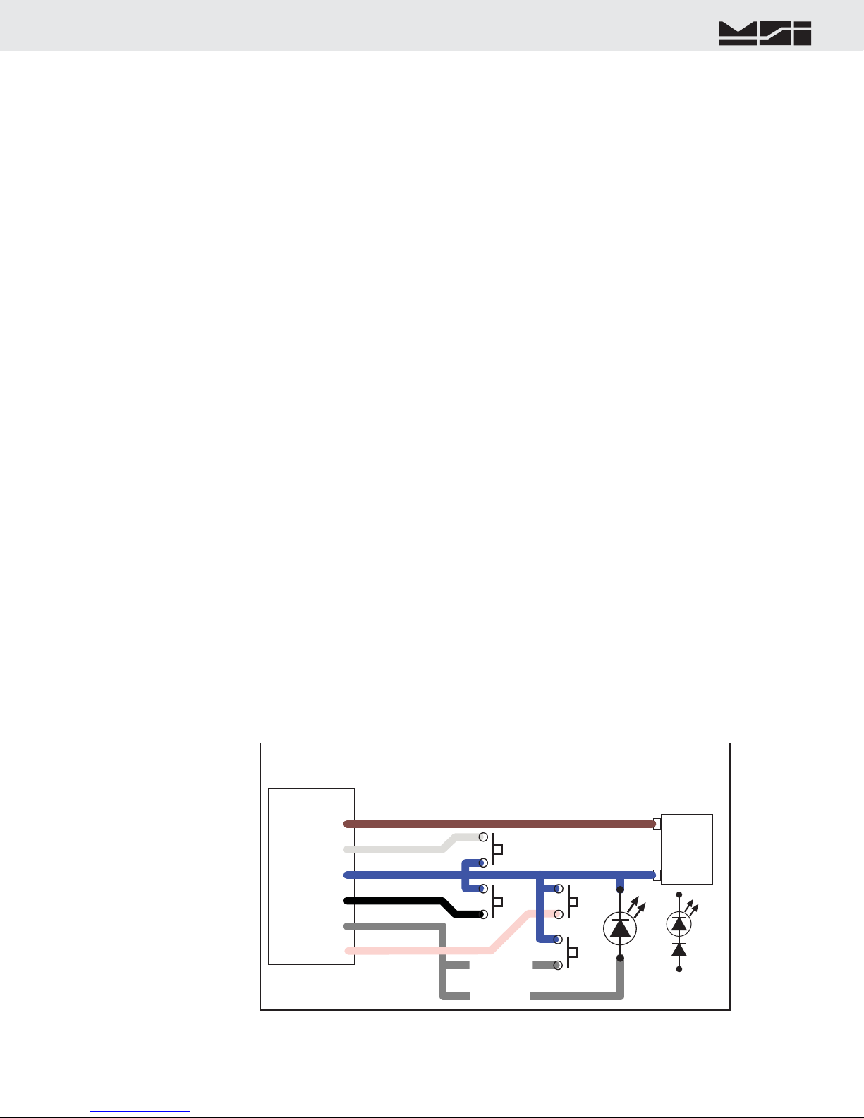
9850P2PWRPORTPin1-Vin+Pin2-SW1Pin3-GNDPin4-SW2Pin5-LEDorSW4SW1AuxPower,RemoteSwitches,RemoteLEDConnectionAuxBatteryorPowerSupplyPowerSource6-25Vdc+–SW2MomentarySwitchesOnlyBRNWHTBLUEBLKGREYPin6-SW3PINKSW3SW4FORLEDFORSW4orLEDSiliconDiodeAddDiodetoallowLEDandSW4LEDInsulateallunusedwires.
Green Connect to Earth Ground.
The negative input and earth ground are isolated internally in the 9850. However, the negative output of the Isolated DC supply is common to the chassis ground. Some systems may require isolating the chassis of the 9850 to avoid ground loops. In this case, the Green wire should be insulated and not connected to earth ground.The 9850’s Isolated DC Supply is protected by an internal Fuse. Panel fusing, if necessary, shoud be 1.5A @12Vdc,
3/4A @ 24V, or 3/8A @ 48V. Due to power on surge currents, slightly increased fuse ratings might be needed,
or use a slow or medium blow fuse type. Total DC input power consumption of the 9850 is below 12 watts, and
is typically 7-8 watts.
AUXPOWERANDSWITCHESAux Power is supplied through a pre-assembled cable (MSI P/N 13195). It provides for DC power in (7-25Vdc),
up to four switches, and a remote LED indicator. The LED indicator provides a remote indication that the 9850
is on and functioning. The switches and LED are supplied by the end user. In combination with the Set Points
Cable, the switch inputs can also be used with standard Isolated Input Modules.
Blue Connect to Battery Negative or supply ground. It is generally best to connect this directly to the battery
or Power Supply negative terminal, or where the negative terminal is attached to the chassis.
Brown Connect to Battery or Power Supply Positive (7-25VDC). Again, a direct battery connection is usually
best to avoid interference with vehicle electrical systems. The CellScale is internally fused. If connected
to a breaker or fuse panel, use 2A at 12V, 1A at 24V. Fast blow or medium blow fuses are acceptable.
White Switch 1 input. Connect to a Normally Open push-button switch. The other switch terminal must con-
nect to the Blue wire (ground). If this feature is not used, insulate the end of the wire to prevent it from
shorting.
Black Switch 2 input. Connect to a Normally Open push-button switch. The other switch terminal must con-
nect to the Blue wire (ground). If this feature is not used, insulate the end of the wire to prevent it from
shorting.
Pink Switch 3 input. Connect to a Normally Open push-button switch. The other switch terminal must con-
nect to the Blue wire (ground). If this feature is not used, insulate the end of the wire to prevent it from
shorting.
Gray Switch 4 input and/or Remote power indication. Connect to the anode of a remote LED. The LED cathode
must connect to the Blue wire (ground). No current limit resistor is required, current drive is provided by
the CellScale (~15mA). Suitable for LEDs with VF 1.6V to 2.4V@ 20mA. Not suitable for Blue or White
LEDs due to their VF >3V. If a fourth switch input is needed, connect to a Normally Open push-button
switch. If this wire is not used, insulate the end of the wire to prevent it from shorting. It is possible to
have the external LED in parallel with SW4. To do this, place a silicon diode (1N4148 or equivalent) in
series with the LED and place the Diode LED assembly across the switch. The current to the LED will
reduce to ~ 9mA (using a AlGaAs Red LED).
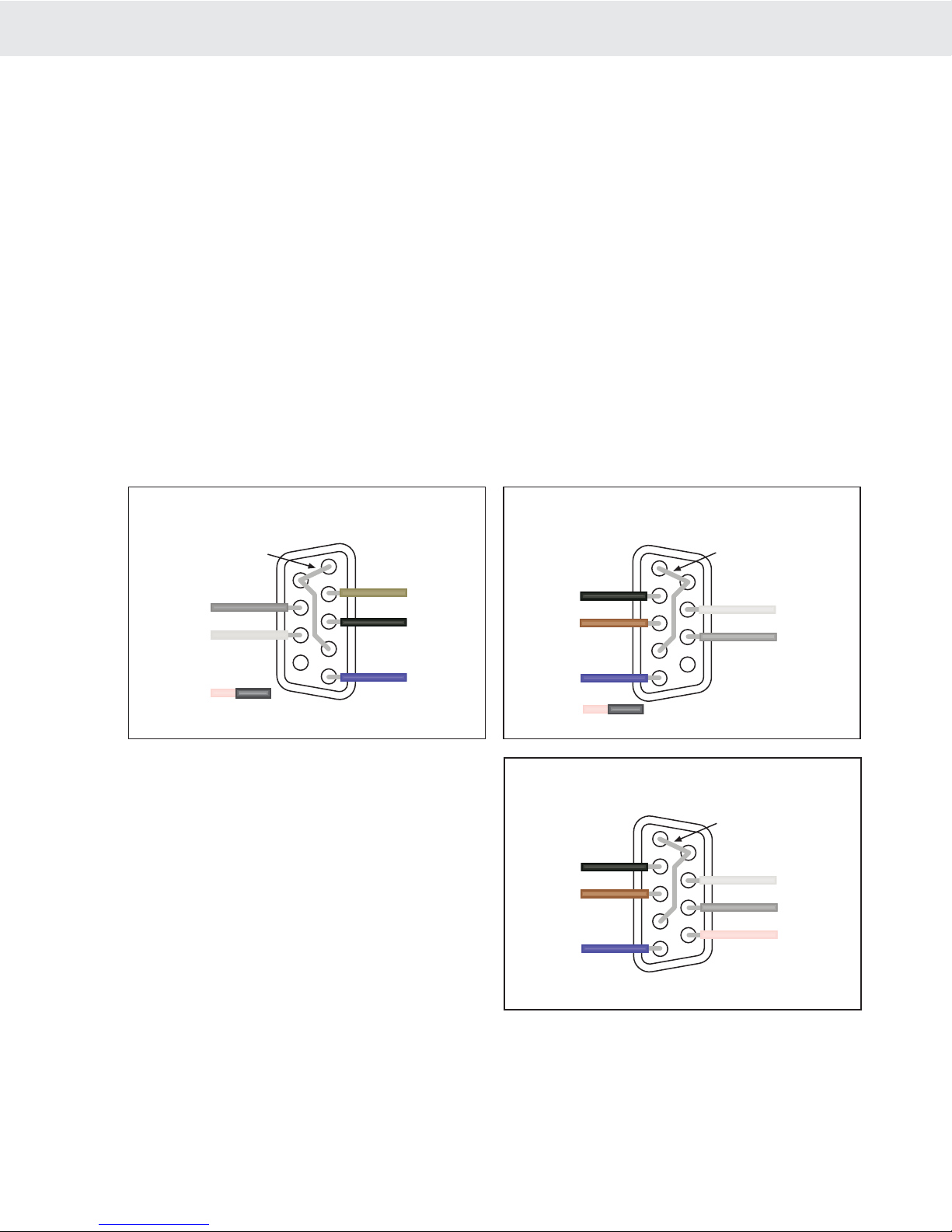
Page 14 MSI-9850 RF Remote Indicator • User GuideMSI-9850HANDHELDRFREMOTEINDICATORforCELLSCALE®SERIALPORTSCommPortCablesThe 9850 comes standard with one Comm Port Cable wired for RS-232 (MSI P/N 502513-0001) following the
AT standard for 9 pin serial cables (DCE). An unterminated cable is available (MSI P/N 10084) if you wish to
wire your own serial cable for RS-232 or RS-422 or RS-485. Comm Ports 1 and 2 are wired identically. Comm
Port 1 functions as an RS-232, 422, or 485 port. Comm Port 2 is RS-232 only, but provides an option for power-
ing a Bar Code Reader.
CommPortCableColorCodeRS-232Brown Transmit output from 9850, connect to receive of DTE.
Black Receive input to CellScale, connect to transmit of DTE.
Grey CTS Input to CellScale. Connect to RTS or RTR output of DTE.
White RTS/RTR output from CellScale. Connect to CTS input of DTE.
Blue Signal Ground
Pink On Comm 1, floating the Pink wire (insulated) sets up the RS-232 Mode. Grounding the Pink wire (to
the blue wire) sets up the RS422/485 mode. On Comm 2, the Pink wire is +5Vdc for powering peripheral
devices such as Bar Code Readers. This is the default function. The Pink wire can also be configured
as an auxiliary digital input or output as determined by the position of JP2 (Contact MSI for further
information).
Drain Wire – Connect to metal shell.
12345678(NC)9Brown(TD)Black(RD)Blue(GND)Grey(CTS)White(RTS)Jumper1-6-4COMM1or2RS-232DCE9-PinFemale‘D’SolderCupViewStandardwiringfordirect9850toComputerconnectionPink(Mode)insulatew/heatshrink
123456789(NC)Brown(TD)Black(RD)Blue(GND)Grey(CTS)White(RTS)Jumper1-6-4COMM1or2RS-232DTE9-PinMale‘D’SolderCupViewWiringfordirect9850toPrinter/ScoreboardconnectionPink(Mode)insulatew/heatshrink
CommPort2RS-232w/BarCodeReaderOptionThe 9850 can supply 5Vdc up to 0.5A for
powering a Bar Code Reader. The 5V supply is
fused and reverse polarity protected. Most Bar
Code Readers can be supplied with power from
Pin 9 of the D-9 connector. The 9850 in its default
configuration supplies 5Vdc on the Pink Wire
unless the function of JP2 is altered. JP2 (9850
Motherboard) must be in position 1-3.
123456789Brown(TD)Black(RD)Blue(GND)Grey(CTS)White(RTS)Jumper1-6-4COMM2RS-232DTE9-PinMale‘D’SolderCupViewWiringfordirect9850toBarCodeReaderconnectionPink(+5V)Requires5VBarCodeReaderwithpowercon-nectedtoPin9.9850JP2positioned1-3.
RS-422/485Operation-CommPort1RS-422 and RS-485 serial connections are used when long wire runs are necessary. The 485 spec covers cable
runs up to 4000’. 422 and 485 are differential transmissions and require twisted pair wiring to achieve common
and normal mode rejection. Although short runs of 422/485 cabling are often just two wires, a ground reference is
required. Usually the ground reference is connected through resistors to prevent ground differential current flow.
RS422/485 connections require a termination resistor to reduce reflections. See wiring diagrams for details. The
9850 features a software switchable termination resistor.

MSI CellScale® System • 9850 User Guide Page 15
MEASUREMENTSYSTEMSINTERNATIONAL
Firmware Version 5-XX for 2450 Modems
Both RS-422 and RS-485 are multi-drop capable.
The 9850 can drive up to 32 receivers on one
twisted pair. Although the 9850 uses standard RS-
485 drivers, the 9850 firmware does not have a full
duplex protocol. Contact MSI for custom solutions
for networking with RS-485.
CommPortCableColorCodeRS-422/485Applies to Comm Port 1 OnlyBrown TD- (Z)
White TD+ (Y)
Black RD+ (A)
Grey RD- (B)
Blue Signal Ground
Pink Ground (to Blue) to configure port for
422/485
Drain Wire Connect to metal shell.
If the 9850 is the final device in a chain, enable
the termination resistor (see Comm Port Menus).
Install a 120Ω resistor at the end of the cable across
RD+ and RD-.
485Receiver485Receiver485Receiver485ReceiverBROWNWHITEBLUEShieldDrain485TerminationResistor.120Ω1/4WFinalreceiveronly.TerminateShieldatonlyoneend.Multi-dropOutput
+–+–+–
GndPinkWiretoenable422/485Mode
+–
9850COMMPORT1Pin1-TD-(Z)Pin2-TD+(Y)Pin3-GNDPin4-RD+Pin5-RD-Pin6-Mode
PINK
9850COMMPORT1Pin1-TD-(Z)Pin2-TD+(Y)Pin3-GNDPin4-RD+(A)Pin5-RD-(B)TD+TD-RD-RD+GNDCHASSISGNDIfthe9850isthefinalreceiver,enabletheinternaltermination(Menuchoice).485TerminationResistor.120Ω1/4WFinalreceiveronly.TerminateShieldatonlyoneend.GroundReferenceResistor.100Ω1/2WAtallreceivers.ShieldShieldRS-485/422FullDuplexConnectionRemoteDeviceUpto1000metersBRNWHTBLUEBLKGREYPin6-ModePINK9850COMM1only
SETPOINTSOUTPUTSetPointsOutputCableThe 9850 can directly drive up to 5 external relays which correspond to the CellScale system Set Points 1-5. The
open drain MOSFET output lines are transient and inductive kickback protected so that no snubber network is
needed for coil relays. The drivers are rated for 5-25Vdc relay coils up to 150mA. The Set Points Port provides
a source of 5V, but limit drain from this source to 500mA total maximum.
Set Point outputs 1-4 are always available. Use of Set Point 5 requires that jumper JP6 on the Processor board is
positioned 1-2. This modification requires SMD soldering skills. Normally the line is connected to circuit ground
to allow a power return for use of the 5V supply. Set Point 5 is also shared with the Audible Alarm option regard-
less of the JP6 setting.
1
2
3
4
5
6
7
8
9
Brown (TD-)
(Z)
Black (RD+)
(A)
Blue (GND)
Grey (RD-)
(B)
White (TD+)
(Y)
Jumper 1-6-4
(Optional)COMM 1 RS-422/485
9-Pin Male ‘D’
Solder Cup View
Pink
(Mode)
120Ω Termination
Resistor (If necessary)

Page 16 MSI-9850 RF Remote Indicator • User GuideMSI-9850HANDHELDRFREMOTEINDICATORforCELLSCALE®
9850P3SetPointsPortPin1-5VOutPin2-SP2Pin3-SP3Pin4-SP5orGNDPin5-SP1SetPointsBRNWHTBLUEBLKGREY5VdcSnubberDiodesnotrequiredDriving5VCoilRelaysLimit150mAeamaxcoilcurrent(or500mATotal)++++Pin5-SP4PINK+UseofSP5requiresJumperJP6positioned1-2.JP6isdefaultedtoGNDandwillturnonanyrelayconnectedtotheblackwirewhenthe9850poweristurnedon.
Insulateallunusedwires.
9850P3SetPointsPortPin1-5VOutPin2-SP2Pin3-SP3Pin4-GNDPin5-SP1SetPointsBRN(NC)WHTBLUEBLKGREY5Vdc-25VdcSnubberDiodesnotrequiredDrivingExternallyPoweredCoilRelaysLimit150mAeamaxcoilcurrentPin5-SP4PINK
InsulateBrnWireInsulateallunusedwires.
JP6indefaultGNDPosition(1-4)
RelayPowerSource+–
++++
Brown Provides a +5V source for driving relays or auxiliary devices. Fused with a self resetting Polyswitch
device. Maximum output current is 500mA total. This output is diode protected and not highly regu-
lated as the regulated voltage passes through a Schottky diode. Since V-forward of the Schottky diode
varies with current drain, the voltage will vary from a low of ~4.9V at 500mA to a high of 5.2V lightly
loaded.
White Open Drain Relay Driver, Set Point 2
Blue Open Drain Relay Driver, Set Point 3
Black Defaults to circuit ground. Power return for the 5V supply. This line can be used to drive a master relay
that turns on when the 9850 turns on. Or by moving JP6 to poisition 1-2, provides an Open Drain Relay
Driver, Set Point 5
Grey Open Drain Relay Driver, Set Point 1
Pink Open Drain Relay Driver, Set Point 4
With 5V relays, no other
power supply is required for
driving relay coils. Other
5V devices such as lamps or
alarms can also be powered
by these lines as long as the
maximum current rating is
observed.
D ri v in g h i gh e r v o lt -
age devices (up to 25V)
requires the use of an exter-
nal supply. JP6 should be in
its default position 1-4 to
provide a ground reference
to the relay power source.
Therefore only 4 outputs
(SP1-4) are available.
When the 9850 is DC pow-
ered, SP5 can be used since
the ground reference is
provided through the power
input.
9850P3SetPointsPortPin1-5VOutPin2-SP2Pin3-SP3Pin4-SP5Pin5-SP1SetPointsBRN(NC)WHTBLUEBLKGREY7Vdc-25VdcSnubberDiodesnotrequiredDrivingExternallyPoweredCoilRelaysLimit150mAeamaxcoilcurrentPin5-SP4PINK
InsulateBrnWireInsulateallunusedwires.
JP6inPosition(1-2)
9850&RelayPowerSource+–
+++++
To9850DCPowerInput.NegativePowershared.

MSI CellScale® System • 9850 User Guide Page 17
MEASUREMENTSYSTEMSINTERNATIONAL
Firmware Version 5-XX for 2450 Modems
12345123451234512345123456789123456789FIELDWIRINGTERMINALSTRIPFUSE5AMODULEPOSITION1234
+VCCGNDGNDGNDGNDLOGICLOGICLOGICLOGIC
TERMINALSTRIPFORLOGIC
9850P3SetPointsPortPin1-5VOutPin2-SP2Pin3-SP3Pin4-SP5orGNDPin5-SP1SetPointsBRNWHTBLUEBLKGREYDrivingOutputModulesPin5-SP4PINKUseofSP5requiresJumperJP6positioned1-2.
Insulateallunusedwires.TOPOSITION5INLARGERRACKGNDConnectionsnotrequiredforOutputmodulesI/ORACKGRAYHILL70RCK4or70GRCK4orEquivalent
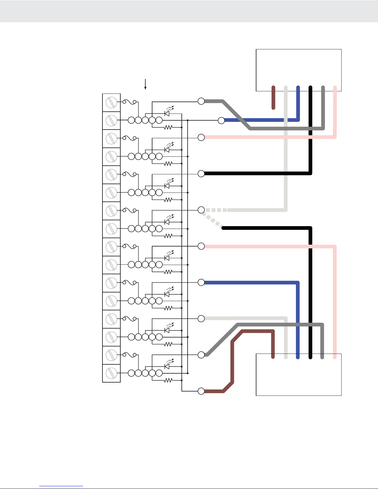
InterfacingIndustryStandardI/OModulesStandard Opto-isolated Output modules are easily driven by the 9850 Output port. MSI provides a 4 port I/O rack
prewired with the Set Points Output Cordset (MSI P/N 10082 + 13186). Hooking up the GND wire (Black) is
optional when driving output modules. Any 5V input compatible Output Module can be used. For reference, the
following Output Modules have been tested with the 9850 and fit Grayhill’s I/O Rack 70RCK4:
Grayhill AC Output Modules
70M-OAC5, 120VAC@3A, Normally-Open Zero Voltage Turn-on
70M-OAC5A, 240VAC@3A, Zero Voltage Turn-on
70M-OAC5A-11, 240VAC@3A, Random Turn-on
Grayhill DC Output Modules
70M-ODC5, 60VDC@3A, Normally-Open
70M-ODC5A, 200VDC@1A, Normally-Open
70M-ODC5B, 60VDC@3A, NO Low off leakage
This list represents only a small number of compatible Output Modules.
Page 18 MSI-9850 RF Remote Indicator • User GuideMSI-9850HANDHELDRFREMOTEINDICATORforCELLSCALE®
12345123451234512345FIELDWIRINGTERMINALSTRIPFUSE5AMODULEPOSITION1234TERMINALHEADERFORLOGIC
9850P3SetPointsPortPin1-5VOutPin2-SP2Pin3-SP3Pin4-SP5orGNDPin5-SP1SetPointsBRNWHTBLUEBLKGREYMixedInputandOutputModulesPin5-SP4PINKUseofSP5requiresJumperJP6positioned1-2.
GNDConnectionrequiredforInputmodulesI/ORACKGRAYHILL70RCK8or70MRCK8orEquivalent1234567891011121314151612345123451234512345567849474543419850P2SwitchesPortPin1-Vin+Pin2-SW1Pin3-GNDPin4-SW2Pin5-SW4BRNWHTBLUEBLKGREYPin6-SW3PINKNC3934Anyevenpin373533OUTPUTOUTPUTOUTPUTOUTPUTINPUTINPUTINPUTINPUT
By combining the Set Points Port P3 with the Switch Input Port P2 a complete I/O interface can be realized. Up
to 5 Outputs and 4 inputs can be serviced by the 9850 as illustrated.
Although not illustrated here, you can still use the Aux Power Input (Brown Wire on P2) to provide backup power
for the 9850. Connect the backup power between Brown (+) and Blue (-).

MSI CellScale® System • 9850 User Guide Page 19
MEASUREMENTSYSTEMSINTERNATIONAL
Firmware Version 5-XX for 2450 Modems
ANTENNASTo meet FCC licensing rules, you must use only antennas supplied or recommended by MSI. MSI offers the 9850
with six antenna choices: 1) Standard Antenna – This is a small 1/2 wave antenna that mounts directly on the
9000 CellScale enclosure and is suitable for most short to medium range applications. 2) Long Range Antenna
– A high gain antenna that is remotely mounted from the 9850 with a low loss coaxial cable. This omnidirectional
antenna increases the range up to 4 times. The 10' cable allows placement of the antenna above the 9850 for
ease of clearing possible obstacles to data transmission. 3) Vehicle Mount Whip Antenna – This antenna mounts
directly to the roof of mobile vehicles and is weatherproof. 4) For maximum range, a 15dBi Gain Yagi Antenna
is available by special order. Please contact MSI for details. 5) Corner Reflector – Often the best choice for a
wall mounted antenna. MSI offers a 14dBi and a 9dBi Corner Reflector. 6) Patch Antenna – For applications
where the standard antenna is vulnerable to physical use or outdoor applications. The Patch antenna is mildly
directional which requires more care in antenna placement for long range applications. Patch Antennas are avail-
able by special order only.
Antenna placement is critical to problem free use of your CellScale system.
1) Be sure a relatively clear transmission path exists between the 9850 and associated CellScale master devices.
The radio signals travel primarily by line of sight (LOS), and obstructions between stations will degrade the
system performance. LOS is less important as distances decrease.
2) When using the long range antenna, mount the antenna on a tower or other elevated structure to ensure that
you have a clear LOS transmission path. This will raise the antenna to a level sufficient to clear surrounding
terrain and other obstructions. It is not necessary or desirable to provide a ground plane for the antenna.
3) Never use a directional antenna (e.g. a Yagi, or a corner reflector) on a mobile system. However, fixed station
locations can often benefit from directional antennas when the location of the other components of the RF
network are always in the same general direction.
4) If using the meter mounted standard antenna, ensure that the antenna is not blocked by any metal. Transmission
is good through most kinds of glass so mounting a meter next to a window should work fine. If there is no
clear line of sight place to mount the 9850, consider switching to a coax connected antenna so the antenna can
be remoted. MSI offers bulkhead Coax kits for extending the antenna cable through a wall or enclosure.
5) The standard and long range antennas are vertical plane devices. Do not mount them sideways. They should
always point up (mounted vertically). It also works to point them down, when high off the ground (such as
on the underside of a large bridge crane). The long range 9dBi Antenna is particularly sensitive to off axis
mounting. Use a carpenters level to ensure the antenna is exactly 90° perpendicular to the earth.
6) Do not mount an omnidirectional Antenna next to a metallic or concrete surface. This can result in reflections
and undesired RF characteristics. For this application, use a Corner Reflector.
7) After installation, you must seal the Antenna connection with an Adhesive Heat Shrink Boot. Failure to seal
the Antenna may result in liquid destroying the Antenna, or the 9850.
MSI does not recommend extending the coaxial cable beyond 3 meters. At 2.4GHz more loss will result from coax losses than are gained by raising the antenna. If you must extend the antenna, use a very low loss 50Ω coax such as RG-214, RF-195, or other low loss varieties. For very short extensions (<1m), cables made with RG-316 are suitable.Downloaded from www.Manualslib.com manuals search engine
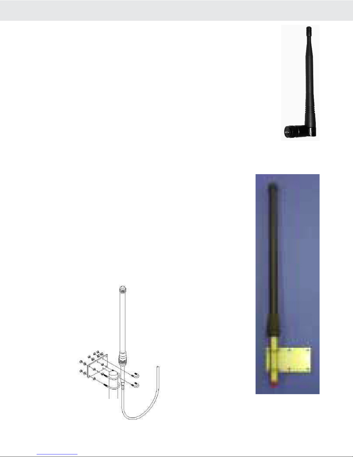
Page 20 MSI-9850 RF Remote Indicator • User GuideMSI-9850HANDHELDRFREMOTEINDICATORforCELLSCALE®STANDARDANTENNAThe Standard Antenna (pictured here) is an articulated 1/2 wave 2dBi gain design with a standard TNC
connector. This antenna and Coax connector, though resistant to water, is not water-proof. Seal the
TNC base with an adhesive heat shrink boot if this antenna is exposed to water. This Antenna should
be vertically oriented.
LONGRANGEOMNI9dBiANTENNAW/PIPEMOUNTThe Long Range Omnidirectional antenna (MSI P/N 12147) is pole
mounted (up to 2” diameter) and extends the range of CellScale transmis-
sions. MSI supplies this antenna with a 10’ (3m) coax cable pre attached.
This antenna must be vertically mounted. The vertical Beamwidth (-3dB
point) is 14 degrees. Also available with an N connector (MSI P/N 12037)
for applications requiring longer coax cable lengths.
Table of contents
Other Measurement Systems International Measuring Instrument manuals

Popular Measuring Instrument manuals by other brands

IBA
IBA KermaX-plus 120-131 E Oem manual

Dover
Dover TWG Tulsa Winch Intelliguard II user manual

Ladybug
Ladybug USB PowerSensor+ LB A Series product manual

HEIDENHAIN
HEIDENHAIN QUICK-CHEK QC-1000 Operation manual

Cropico
Cropico DO7 PLUS operating instructions

LaserLiner
LaserLiner LaserRange-Master Gi7 Pro operating instructions


