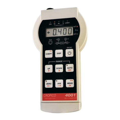
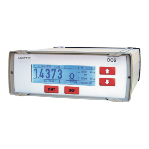
Cropico DO7 PLUS User manual

Digital Microhmmeter
Type DO7 PLUS
Operating Instructions
Bracken Hill, South West Industrial Estate,
Peterlee, Co. Durham SR8 2SW. England.
Tel: +44 (0)191-586 3511 Fax: +44 (0)191-586 0227
www.cropico.co.uk
551A550 Rev 3

Operating Instructions
Digital Microhmmeter Type DO7 PLUS
Limited Warranty & Limitation of Liability
CROPICO guarantees this product for a period of 1 year. The period of warranty will
be effective at the day of delivery.
(c) Copyright 2009
All rights reserved. Nothing from this edition may be multiplied, or made public in
any form or manner, either electronically, mechanically, by photocopying, recording,
or in any manner, without prior written consent from CROPICO. This also applies to
accompanying drawings and diagrams.
Due to a policy of continuous development CROPICO reserves the right to alter the
equipment specification and description outlined in this publication without prior
notice and no part of this publication shall be deemed to be part of any contract for
the equipment unless specifically referred to as an inclusion within such contract.

Operating Instructions
Digital Microhmmeter Type DO7 PLUS
Disposal of Old Product
This product has been designed and manufactured with high quality materials and
components that can be recycled and reused.
When the crossed out wheelie bin symbol is attached to a product it means the
product is covered by the European Directive 2002/96/EC.
Please familiarise yourself with the appropriate local separate collection system for
electrical and electronic products.
Please dispose of this product according to local regulations. Do not dispose of this
product along with normal waste material. The correct disposal of this product will
help prevent potential negative consequences for the environment and human
health.
User Note:
These Operating Instructions are intended for the use of Competent Personnel.

Page No.
Section 1 – Instrument set-up and operation
Table of Contents
1. Introduction
1.1 Overview
1.2 Standard Features of the DO7PLUS
1.3 Definitions and Terminology
1.4 Specification
1.4.1 Measurement Accuracy
1.4.2 Temperature Compensation accuracy
1.4.3 Conditions of Use
1.4.4
1.4.5
Lead Resistance
DC Power Input
1.4.6 External Mains Power Unit
1.4.7 Battery Operation
1.4.8 Weight and Size
2. About the DO7PLUS
2.1 Safety Information
2.2
2.3
2.4
2.5
Unpacking the Instrument
Cleaning Instructions
Battery Pack Replacement
The Front Panel
3. Getting Started
3.1 Battery charger
3.2 About the Display Screen
4 Instrument Set-Up
4.1 Setting the DO7PLUS instrument configuration
4.2 Instrument SET UP table
4.3 Setting the DO7PLUS measurement configuration
4.4 Measurement configuration table
4.5 Setting the Range
4.6 Setting the measurement current
4.7 Zero Mode
4.8 Short cut keys
4.9 Menu options explained
4.9.1 Range
4.9.2 Current
4.9.3 Trigger
4.9.4 Limits
4.9.5 Data Log
4.9.6 Statistics
4.9.7 Graphics
4.9.8 Cooling Curve
4.9.9 Temperature Compensation
4.9.10 Filter
4.9.11 Settling
4.9.12 Cable Mode
4.9.13 Memories
5. Measuring with the DO7PLUS
5.1 Connecting to the DO7PLUS
5.2 Connecting to the resistance
5.3 Resistance Measurement
5.4 Measurement with temperature Compensation
5.5 Effects of lead resistance
6. Calibration
7. Firmware Update
8. RS232 Connection Diagram
9. Accessories
Section 2 Remote control Interface
Operating Instructions
Digital Microhmmeter Type DO7 PLUS
4
5
5
6
6
6
6
6
6
6
6
6
7
8
8
9
9
9
10
12
12
12
14
14
15
16
16
18
19
20
20
20
20
20
21
22
23
24
25
26
27
28
29
30
30
32
32
32
34
34
34
35
37
37
38

1 INTRODUCTION
1.1 OVERVIEW
The DO7PLUS Microhmmeter is a high accuracy instrument designed for industrial and
laboratory resistance measurements. Its rugged case and robust construction ensures that
accurate and reliable measurements are delivered even under the harshest of environments.
The DO7PLUS is a true four wire measuring instrument eliminating the need to compensate
for lead resistance. The measured value is displayed in large characters with decimal point
and units kΩ, Ω, or mΩ. For maximum accuracy the measuring current may be automatically
reversed and the average of measurement displayed. For measurements on unstable
samples, a rolling average filter is available.
Resistance measurement accuracy is typically 0.05% (1 year specification) and the value may
be displayed with or without temperature compensation.
The front panel measurement connections are made via 4mm sockets located on the front
panel. The connection to a Pt100 temperature sensor is made with a Micro Buccaneer 400
series connector. For remote control both USB and RS232 interfaces are available which will
also enable the instrument firmware to be updated from a PC.
The included data-log function has the ability to display logged values in a table or graphical
format and notes may be added to each logged value. The DO7PLUS also has the facility to
automatically measure and calculate cooling curves displaying in both graphical and numeric
formats. This makes the DO7PLUS the ideal instrument for machine testing.
Hi/Lo limits are a standard feature
Operating Instructions
Digital Microhmmeter Type DO7 PLUS
4

1.2 Standard features of the DO7PLUS Microhmmeter include:
x Graphical and Numerical display of electrical machine cooling curves
x Automatic temperature compensation
x Fast reading rate 2 measurements per second
x Measuring ranges from 6 mOhm to 6 kOhm
x Resolution 100 nOhm on 6mOhm range
x Up to 10 Amp measuring current
x Continuous measurement for inductive samples, single pulse measurement for fast
resistance tests
x Full test lead continuity testing
x Hi/Lo Limits with Red/Green front panel warning LEDS
x Switched current mode with automatic averaging ensures elimination of thermal emf
errors
x Multi lingual graphic LCD display for resistance measurement values as well as
configuration settings and statistical results.
x Advanced functions include data logging and statistical reporting with max/min, average
values, peak to peak value, and standard deviation. Full QWERTY keyboard for adding
notes to logged measurements
x RS232 and USB interfaces available for automated monitoring and controlling
applications
x Graphical display of logged values
x Full range of measurement accessories
1.3 Definitions and Terminology
nnano Ohm 0.000000001 Ohm
P: micrOhm 0.000001 Ohm
m:milliOhm 0.001 Ohm
k:kilOhm 1000 Ohm
Pt100 Platinum resistance sensor (100:at 0qC)
+U/-U Voltage connection
+I/-I Current connection
Four terminal Kelvin principle of measurement using 2 wires (+I and -I) to pass
measurement current through Rx and 2 wires (+U and -U) to measure the
voltage.
Kelvin clips Crocodile clips with isolated jaws, one side being the current I
connection, the other voltage U connection.
km Indicates cable length in Kilometres
m Indicates cable length in metres
Cooling Curve A method of determining the maximum temperature of an
electrical machine when running at full load
Operating Instructions
Digital Microhmmeter Type DO7 PLUS
5

1.4 Specification
Prior to connecting this instrument always ensure that the circuit under test is electrically
isolated. Connecting this instrument to circuits which have not been isolated could lead to
a hazard.
1.4.1 Measurement accuracy
1.4.2 Temperature compensation accuracy
The accuracy of the temperature measurement is ±0.1% and uses a standard Pt100 sensor
(EN60751). This accuracy does not include errors due to the sensor itself. The temperature
measurement range is 0…+100°C and the default resistance measurement is referenced to
20°C when this option is used. Other reference temperatures may be selected by the user
over the range 0°C to +50°C
1.4.3 Conditions of use
The DO7PLUS is suitable for indoor and outdoor operation.
Maximum altitude: 2000m
Installation category: 50V CATIII
Pollution degree: 2 (according to IEC61010-1)
Storage temperature: -20°C…+50°C
Operation temperature: 0°C…+40°C
Relative humidity: up to 90% non condensing @ 31°C
IP Rating: IP 53 with lid open
IP 67 with lid closed
1.4.4 Lead resistance
The DO7PLUS will operate with long lead lengths providing the maximum lead resistance
does not exceed the following:
Current Leads Maximum resistance 60meach lead (120 mtotal)
Potential leads Maximum resistance 1keach lead (2ktotal)
1.4.5 DC Power Input
9–36VDC, 4A max
1.4.6 External Mains Power Unit
External mains psu 90V...253V, 47Hz...63Hz. Interchangeable leads International use (only
one lead supplied with instrument).
1.4.7 Battery Operation
Two internally fixed NiMH battery packs, with gas gauge circuits to monitor battery capacity.
An internal battery charger for each battery provides intelligent charging with automatic fast
and maintenance charging as required. The percentage of full charge for each battery is
indicated on the LCD display.
Range Measuring
Current Resolution FSV Accuracy at full rated current
6.0000m10A 100nΩ60mV ±(0.05%Rdg+0.01%FS)
60.000m1 A 1μΩ60mV ±(0.05%Rdg+0.01%FS)
600.00m100mA 10μΩ60mV ±(0.05%Rdg+0.01%FS)
6.0000Ω10mA 100μΩ60mV ±(0.05%Rdg+0.01%FS)
60.000Ω1mA 1mΩ60mV ±(0.05%Rdg+0.01%FS)
600.00Ω100μA 10mΩ60mV ±(0.05%Rdg+0.01%FS)
6.0000kΩ100μA 100mΩ600mV ±(0.05%Rdg+0.01%FS)
Operating Instructions
Digital Microhmmeter Type DO7 PLUS
6

1.4.8 Weight and Size
Size: 358 x 269 x 155 mm (W D H)
Weight: 6.0 kg instrument only
Weight Packed: 8.5kg
Operating Instructions
Digital Microhmmeter Type DO7 PLUS
7

2 About the DO7PLUS
This section introduces you to the features and functions of the DO7PLUS Microhmmeter
2.1 IMPORTANT SAFETY INFORMATION
If this instrument is used in a manner not specified in this document the protection provided
by this instrument may be impaired.
The instrument and all associated cables and leads must be checked for signs of damage
before the instrument is operated.
GENERAL
This instrument has been designed and tested to comply with the Electromagnetic
Compatibility Directive 89/336/EEC and Low Voltage Directive 93/68EEC in accordance with
EN 61010 -1 :2001 CatIII <50V relating to the safety requirements for electrical equipment for
measurement, control and laboratory use.
Before connecting the instrument to the mains supply, please ensure the following safety
precautions have been read and understood.
SAFETY SYMBOLS
The following symbols are used to describe important safety aspects of this instrument. These
symbols appear on the instrument and in the operation instructions.
Attention Symbol: Indicates a potentially hazardous condition exists and that it is necessary
for the operator to refer to the instruction manual to ensure the safe operation of this
instrument.
·
Caution - Risk of Electric Shock: Indicates hazardous voltages may be present.
Refer to the instruction manual for further safety information.
SUMMARY OF SAFETY PRECAUTIONS
The following general safety precautions must be observed while operating or servicing this
instrument. Failure to comply with these precautions may result in personnel injury or death.
LIVE CIRCUITS DANGER
Do not connect the power supply to, or operate this instrument with, the protective covers
removed. Component replacement and internal adjustments must be made by qualified
service personnel. Do not replace components with the power cable connected. Under certain
conditions, dangerous voltages may exist with the power cable removed. To avoid injuries
always disconnect power and discharge circuits before touching them.
DO NOT MODIFY THIS INSTRUMENT OR SUBSTITUTE PARTS
Because of the danger of introducing additional hazards, do not perform any unauthorised
modification or install substitute parts to the instrument. Only fuses with the rated current,
voltage and specified type should be used. Failure to do so may cause an electric shock or
fire hazard. Return the instrument to CROPICO for service and repair to ensure the safety
features are maintained.
DO NOT OPERATE IN EXPLOSIVE ENVIRONMENTS
The operation of this instrument in such an environment constitutes a safety hazard.
CERTIFICATION
CROPICO certifies that this product met its published specifications at the time of shipment
from our factory. All calibration measurements performed in the manufacture of this
instrument are traceable to National and International standards.
ASSISTANCE
For after sales support and product service assistance please contact CROPICO Customer
Support Group. Contact information is provided in the operation instruction manual.
Operating Instructions
Digital Microhmmeter Type DO7 PLUS
8

2.2 Unpacking the instrument
When you unpack the DO7PLUS, check that the following items are present before starting to
use the unit:
• 1 x Printed Operating Instructions
• 1 x DO7PLUS Microhmmeter
• 1 x Power supply unit
• 1 x CDROM
• 1 x Calibration Certificate
• 1 x Standard lead pack LS05-P
• 1 x Standard USB lead
• 1 x RS232 lead
• 1 x Warranty Card
Please contact the CROPICO Customer Support Team immediately if any of these items are
missing or damaged.
Please note that we offer a wide selection of measuring leads and test fixtures, see section 9.
Please consult our sales staff to order the items most suited to your application.
2.3 Cleaning Instructions
The instrument should be cleaned using a soft cloth slightly dampened with water. No other
cleaning solvents should be used as these may damage the surface of the instrument.
2.4 Battery Pack Replacement
- Ensure all leads are removed from the front panel of the instrument.
- Ensure the instrument is turned off.
- Remove the 10 front panel screws and sealing washers and store in a safe place.
- Carefully lift out the front panel together with the main measuring unit.
- Remove both plugs from the battery pack by simply pulling them out.
- Place the unit safely to one side.
- Remove the 3 screws and sealing washers from the rear of the case and store in a safe
place.
- The battery pack can now be lifted out of the case.
- Place the new battery pack (Cropico part no 551A675) in the case and refit the rear panel
screws and sealing washers.
- Plug the main unit battery leads back into the battery.
These are colour coded – if the plugs are fitted into the wrong sockets no damage will be
done, but the instrument will not operate.
- Ensure the plugs are fully inserted
- Replace the main unit and secure with the front panel screws and sealing washers.
- Turn the power on. Three warning beeps will alert you to the LCD message that new
batteries have been fitted. Press ‘OK’ to continue.
- It is strongly recommended that the batteries be fully recharged. This will ensure the
internal “gas gauge” circuits are correctly calibrated.
- Do not open the battery pack, but return to Cropico for safe disposal.
Operating Instructions
Digital Microhmmeter Type DO7 PLUS
9

ON/OFF Switch
The On/Off switch switches the DO7PLUS on and off. The last measurement and function
setup is restored at power on. Auto switch-off to preserve battery life may be set between 10
and 60 minutes.
The Function Keypad F1...F5
All DO7PLUS measurements and programming facilities are accessed through the function
keypad (F1...F5). A brief description of these key functions are given in the following table.
For a detailed description of how to use the keys to configure and operate the DO7PLUS,
refer to section 4
Key Symbol Description Function
F1 RANGE Manual or automatic range can be set
F2 CURR Current mode can be selected +I , -I,
Average, or Zero
F3 MENU Displays all measurement
configuration details
F4 SET UP Displays DO7PLUS configuration
including date, time, language etc.
F5 EXIT/ADD NOTE If datalog is on & has one or more
entries allows test notes to be added
QWERTY Keypad
The full QWERTY keypad allows notes to be entered against logged measurement values
1
2
3
2.5. The Front Panel
1
2
3
4 5
6
7 8
9
10
11
12
13
Operating Instructions
Digital Microhmmeter Type DO7 PLUS
10

MEASURE / STOP
Starts and stops the measurement in continuous measurement mode. Triggers measurement
in single measurement mode.
Navigation and enter Key
Moves display cursor and confirms selection.
LIMITS Pass / Fail LEDS
When limit function is set the green led lights to confirm measurement is within limits. Red led
lights if the measurement is outside the set limits.
Power input socket
For connection of power supply or optional car lead to charge batteries.
Charger status Indicator
LEDS indicate state of battery charging.
USB Socket
For connection of USB cable enabling full computer control.
RS232 Socket
For connection of RS232 cable enabling full computer control.
Pt100 input Socket
For connection of Pt100 temperature sensor.
Measurement input sockets
Prior to connecting this instrument always ensure that the circuit under test is electrically
isolated. Connecting this instrument to circuits which have not been isolated could lead to
a hazard.
Four 4mm safety sockets for connection of measurement leads.
Measurement Display
Displays measured values and information screens.
4
5
6
7
8
9
10
11
12
13
Operating Instructions
Digital Microhmmeter Type DO7 PLUS
11

3 GETTING STARTED
3.1 Battery Charger
The DO7PLUS is powered by two internal NiMH batteries. A 6V battery supplies power to the
display and operating circuits, and a 3V battery supplies the measuring current. Once the
power supply is connected to the socket (7) charging is automatic and regulated to ensure the
batteries are kept in the best possible condition. Charge status LEDS (8) show the charging
status for each battery independently. The green READY LEDS will light when batteries are
sufficiently charged for a measurement. The TOP-OFF LEDS indicate a low maintenance
current and the FAST LEDS indicate the batteries are being charged with maximum current. If
a fault condition occurs then the FAULT LEDS will illuminate. Should this occur the instrument
should be taken out service and returned to a Cropico service centre for investigation and
rectification. The power supply should not be opened, dismantled or mechanically interfered
with.
In addition to the mains power supply provided with the DO7PLUS, a charging lead with car
style plug is available as an option enabling the DO7PLUS to be charged with 12 or 24 Volts
DC whilst away from base.
Note: To ensure correct charging operation, the DO7Plus must be switched off during battery
charging.
3.2 About the DO7PLUS Display screen
The display is a graphic LCD panel with backlight giving good readability and contrast. Full
measurement information is displayed with the measured value in large bold text. The
measurement set-up parameters are shown in a clear and unambiguous way.
Figure 3.2.1 - Example of Resistance Measurement Mode
RANGE: 6k100μA ( +VE )
+5.0589 k
FUNCTION STATUS
TRIGGER
LIMITS
FILTER
SETTLING
DATA LOG
SING
OFF
OFF
OFF
OFF
BATT (3V)
BATT (6V)
98%
92%
STOP
RANGE CURR MENU SET UP
A
C
D
B
Operating Instructions
Digital Microhmmeter Type DO7 PLUS
12

Measurement Window
Displays:
x Measured value with sign and units.
x The selected measurement range, current and measurement mode.
x RX+ and RX- value when in average mode.
x Compensated value and measured Rx value plus temperature when in
temperature compensation mode.
Function Window
Displays :
x Trigger mode selected
x Limits status ( OFF, <<Hi>>, <<Lo>> , >>OK<< )
x Filter settings
x Settling settings
x Data Log Status
x Timer (if active)
Status Window
Displays :
x Battery charge state in % of full charge
x Memory number
x Remote status
x Measure / Stop condition
Function Soft Keys
x Five soft keys give access to setup menus
A
B
C
D
Operating Instructions
Digital Microhmmeter Type DO7 PLUS
13

4 Instrument Set-up
4.1 Setting the DO7PLUS instrument configuration
These are the instrument housekeeping settings and once your preferences are selected and
stored they will seldom need to be changed.
To select and change a setting proceed as follows:-
PRESS F4 (SETUP) and the following screen will display
HINT: To navigate around the screen use the navigation arrows
Where an item is highlighted with an arrow
this indicates that additional options are available for that parameter and the right
navigation arrow should be pressed to reveal those options.
The table Fig. 4.2.1 below shows the options available together with a brief description
BACKLIGHT
SETUP MENU
EXIT
BACKLIGHT 60 SECS
A
UTO OFF 15 MIN
KEY BEEP OFF
BEEPER ON
DATE FORMAT DD/MM/YY
DATE 29/04/08
TIME 16:23
LANG ENG
LINE FREQ 50HZ
TEMP UNIT GC
BACKLIGHT
Operating Instructions
Digital Microhmmeter Type DO7 PLUS
14

4.2 F4 SETUP
To enter the configuration menu PRESS F4 (SETUP) the following can then be set.
Fig4.2.1
FUNCTION OPTIONS Description
OFF Switches backlight OFF
ON Switches Backlight ON
BACKLIGHT
AUTO 10–60
seconds
Automatically switches off after 10...60
seconds selectable
OFF Disables Auto-OFF
AUTO OFF ON 10-60
minutes
Automatically switches off after 10...60
minutes selectable
OFF Switches beep on key press OFF
KEY BEEP ON Switches beep on key press ON
OFF
BEEPER ON
Switches warning Beep ON or OFF
DD/MM/YY
DATE FORMAT MM/DD/YY Displayed date format may be selected
DATE 28/04/08 Correct date may be entered
11:37
TIME (HH:MM) Correct time may be entered
ENG Selects English Language
FRA Selects French Language
LANGUAGE
DEU Selects German Language
50Hz Selects 50Hz line frequency
LINE FREQUENCY 60Hz Selects 60Hz line frequency
qC Selects qC temperatures for displayTEMPERATURE
UNIT qF Selects qF temperature for display
9600
BAUD RATE 19200 Selects interface baud rate
OFF
REMOTE
TALK ONLY ON Switches Talk Only mode OFF or ON
VERSION Ver 1.0 Version of firmware installed
PASSCODE
Enables Passcode to be changed,
Passcode is required for calibration
menu and to update firmware.
Factory set Passcode = 9252
CAL See section 6 for Calibration Mode
Operating Instructions
Digital Microhmmeter Type DO7 PLUS
15

4.3 Setting the DO7PLUS Measurement Configuration
To set or change a measurement configuration PRESS F3 (MENU) and the following screen
will display
HINT: To navigate around the screen use the navigation arrows
Where an item is highlighted with an arrow
this indicates that options are available for that parameter and the right navigation
arrow should be pressed to reveal those options.
The table Fig. 4.4.1 below shows the options available together with a brief description
4.4 F3 MENU (Measurement Configuration)
To enter the measurement configuration menu PRESS F3 (MENU) the following can then be set.
Fig 4.4.1
FUNCTION OPTIONS OPTIONS 2 DESCRIPTION
6K
600
60
6
600m
60m
6m
AUTO1
RANGE
AUTO2
Selects the range required
or automatic range
selection. AUTO1 selects
automatic ranging starting
with the 6krange. AUTO2
selects automatic ranging
starting from last selected
range
+I Selects measurement
current in positive direction
-I
Selects measurement
current in negative direction
AVERAGE
Measures with +I then with
–I and displays average
CURRENT
MODE
ZERO
Measures emf in circuit and
deducts from measurement
SINGLE Single pulse measurement
MEAS CONTINUOUS Continuous measurement
MAN Manual trigger with
measure key
TRIGGER
AUTO
AUTO
Automatically triggers
measurement when test
leads are connected
OFF Switches Limits OFF
ON Switches Limits ON
MAX MAX LIMIT = Set Limit Max Value
LIMITS
MIN MIN LIMIT = Set Limit MIN Value
INSTRUMENT MENU
EXIT
BACKLIGHT 6K
CURRENT AVERAGE
TRIGGER SING/AUTO
LIMITS OFF
DATA LOG ON
TEMP COMP OFF
FILTER ON
SETTLING OFF
CABLE MODE OFF
MEMORIES OFF
RANGE
RANGE
Operating Instructions
Digital Microhmmeter Type DO7 PLUS
16

FUNCTION OPTIONS OPTIONS 2 DESCRIPTION
OFF Switches Data Log OFF
ON Switches Data Log ON
REVIEW
Displays logged
measurements
DELETE DELETE DATA LOG Deletes all logged values
No RDGS Number of readings = Enter number of readings
TIMER Timer Interval = Enter time interval between
logged readings
FROM Enter log starting number
for stats calculation
STATS
TO Enter log ending number
for stats calculation
MODE
DATD RANGE
STATS
DATA LOG
GRAPHICS
EXIT
See section 5.10.7 for
details of Graphics
OFF
Switches temperature
compensation OFF
ON
Switches temperature
compensation ON
Pt100
Selects temperature
measurement with Pt100
external probe
TEMP
MANUAL Temperature = Enter temperature manually
Cu (3930) Temperature coefficient of
copper 3930ppm/qC
Al (4030) Temperature coefficient of
Aluminium 4030ppm/qC
USER 1 Coefficient = Enter temperature
coefficient
COEFF
USER 2 Coefficient = Enter temperature
coefficient
TEMP
COMP
REF TEMP Reference temperature = Enter temperature 0 to
50qC
OFF Switches FILTER OFF
ON Switches FILTER ON
No RDGS Number of readings =
Enter number of readings
between 2 and 50 to be
averaged
FILTER
RESET Resets filter average to
zero
OFF Switches SETTLING OFF
ON Switches SETTLING ON
No RDGS Number of readings =
Enter number of readings
to be within settling limit
2 to 999
SETTLING
LIMIT Settling Limit = Enter number of digits
change permitted 1 to 999
Operating Instructions
Digital Microhmmeter Type DO7 PLUS
17

FUNCTION OPTIONS OPTION 2 DESCRIPTION
OFF Switches cable mode OFF
No
CABLES Cables = Enter number of cables to be
measured
Series Cables connected in series
CONN Parallel Cables connected in parallel
LENGTH Length = Enter length of cable
METRE
LENGTH
UNIT KILOMETRE Select units required
No
CABLES Cables = Enter number of cables to be
measured
Series Cables connected in series
CONN Parallel Cables connected in parallel
RES/m Resistance = Enter resistance of cable in /m
METRE
CABLE
MODE
LENGTH
UNIT KILOMETRE Select units required
F2
RECALL Select Memory Number Recalls all settings for memory
number recalled
F3 STORE Select Memory Number Saves all settings in memory
number selected
F4 CLEAR Select Memory Number Deletes all stored data in memory
number selected
MEMORIES
F5 LIST Lists all memory status
4.5 Setting the Instrument Range
Some of the measurement functions need to be changed more frequently than others and
these may accessed directly, to change the RANGE settings PRESS F1 and the following
screen will display.
F1 RANGE
The F1 function key will take you straight to the range set-up menu
HINT: To navigate around the screen use the navigation arrows
To select the highlighted range PRESS OK (F5) or the carriage return key
Pressing the left arrow will return you to the measurement screen without
selecting the new highlighted range.
Pressing F1 (ESC) escapes the range menu and returns to the measurement
screen without updating the range.
AUTO RANGE
Two modes of auto-range may be selected AUTO1 where the DO7PLUS will start at the
highest range and work down. AUTO2 selects the last range used and then ranges up or
down.
HINT: The AUTO2 will often find the correct range the fastest
AUTO1 will always start with the highest range which uses the smallest measuring current
and will avoid overheating temperature sensitive devices.
INSTRUMENT MENU
RANGE:
600
60
6
600m
60m
6m
AUTO1
AUTO2
6K
ESC OK
Operating Instructions
Digital Microhmmeter Type DO7 PLUS
18

Do NOT use Auto-range when measuring inductive devices e.g. motors and transformers.
Fig 4.5.1 Measuring ranges with maximum current and resolution
Range Measuring Current Resolution
6.0000m10A 100nΩ
60.000m1 A 1μΩ
600.00m100mA 10μΩ
6.0000Ω10mA 100μΩ
60.000Ω1mA 1mΩ
600.00Ω100μA 10mΩ
6.0000kΩ100μA 100mΩ
4.6 Setting the Measurement Current Mode
F2 Current
The F2 function key will take you directly to the measurement current set-up menu
HINT: To navigate around the screen use the navigation arrows
To select the highlighted mode PRESS OK (F5) or the carriage return key
Pressing the left arrow will return you to the measurement screen without
selecting the new highlighted range.
Pressing F1 (ESC) escapes the range menu and returns to the measurement
screen without updating the range.
+ I The measurement current flows in the positive direction
- I The measurement current flows in the negative direction
AVERAGE The measurement is made with +I current then a second measurement with
-I current, and the average value of the two measurements is displayed. The
average measurement will eliminate the effects of thermal emf and is
recommended for all resistive measurements.
WARNING: The AVERAGE mode should NOT be used when measuring inductive samples
such as transformers or motor windings. In these cases use the +I mode which will give
continuous and uninterrupted measurement current, ensuring the inductance is fully charged
and the correct reading displayed.
INSTRUMENT MENU
CURRENT: +I
-I
ZERO MODE
ESC OK
AVERAGE
Operating Instructions
Digital Microhmmeter Type DO7 PLUS
19
Table of contents
Other Cropico Measuring Instrument manuals


