Meatest M550 User manual


M550 Impedance calibrator is designed for LCR meter verification and calibration. The calibrator integrates
partial resistance standards in decade series with range of values from 100 mup to 100 M, capacitance
standards with range from 10 pF up to 100 µF and inductive standards with the range from 10 µH up to 10 H.
For test leads and unit under test electrical zero compensation the calibrator is equipped with reference
positions of short-circuit terminals SHORT and open-circuit terminals OPEN. Summary frequency range
covers band from 20 Hz up to 1 MHz, however some partial standards have lower applicable frequencies.
Partial standards feature low temperature coefficient, excellent long term stability and low frequency
dependency.
The calibrator offers two banks of standards. The more accurate bank is equipped with four output BNC
connectors. It is aimed for calibration of LCR meters based on auto-balancing bridge principle using four-
pair-terminal technique (4TP) of test terminal connection. The second bank (4W/2W) is equipped with 4mm
output banana terminals and it’s aimed for calibration of LCR meters based on I-V method with non-coaxial
test terminals. Practically this bank can be used in four-wire (4W) or two-wire (2W) measurements.
M550 has a built-in test signal level meter which can be easily used for verification of test signal voltage,
current and frequency. Color LCD display shows parameters of a selected standard, set-up configuration,
calibration data accuracy and other useful information.
Impedance calibrator should be periodically recalibrated. Recommended recalibration interval is 1 year.
Internal calibration data are accessible via front panel keyboard. Calibration memory is protected with a
calibration password.
All functions of the calibrator can be controlled by IEEE-488 interface or via RS-232 serial line.

Main control segments of the calibrator are:
1. Output terminals –Calibrator contains two sets of output terminals. Both sets are electrically isolated
from each other.
4TP –coaxial BNC output for calibration of BNC terminal LCR meters. Shielding of the BNC
connectors is isolated and connected together inside the bank of standards in one point to obtain the
lowest frequency dependency. 4TP output is suitable for calibration of LCR meters with coaxial input
connectors.
4W/2W –4mm banana non-coaxial output for calibration of four and two wire LCR meters. While in
4W mode all four terminals are applied for DUT connection, in 2W mode only HCUR and LCUR
terminals have defined impedance parameter.
Note: In 2W mode both HCUR –LCUR and HPOT –LPOT terminals are connected to internal partial
standard however calibration values are defined between HCUR –LCUR terminals.
Meaning of individual terminals is as follows:
HCUR high source current terminal
HPOT high sense voltage terminal
LPOT low sense voltage terminal
LCUR low sense current terminal
2. Display –More in chapter 1.1.1.
3. Numeric keys –Numericalvalues can be entered from the keyboard. ENTER button is used to confirm
the selection. CANCEL button is used to cancel the entry.
4. Function keys –Function buttons can be used to call up the functions of the calibrator directly.
5. System keys –Group of buttons enable access to system parameters
6. Selection of output mode –The buttons enable selection one of two outputs either 4TP or 4W/2W and
switching output terminals ON/OFF.
7. Rotary knob –The rotary knob integrates several functions. By turning the knob to the left or right,
the user can:
-Step through the options in menus
-Select L-C-R partial standard according to its nominal value
-Enter numerical values
When making a menu selection, pushing in on the knob is equivalent to pressing the SELECT soft
key. When editing a number, pressing in on the knob will switch between moving the cursor between

characters and changing the selected character’s value. Arrow icons above and below the selected digit
indicate which of the two modes are active.
8. Soft keys - There are five buttons below the display, which meaning changes depending on the content
of the display. These buttons usually call up local menu with parameters setting, modes, etc. or enable
to close currently opened function or menu.
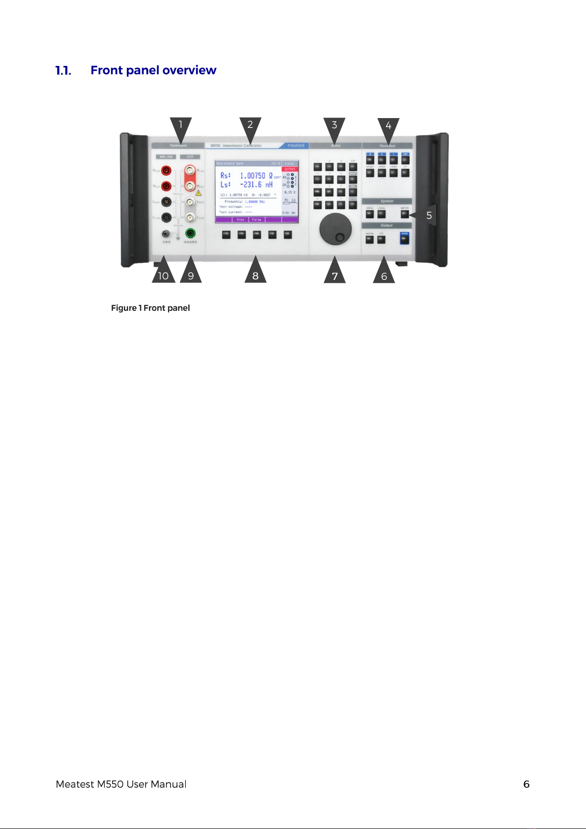
9. Guarding terminal –Guarding terminal. It is connected to shielding of the 4TP coaxial output
connectors. It has no function in 4W or 2W mode.
10. Grounding terminal –Grounding post is joined to metal parts of housing and to protective earth in
power line socket.
Display is divided into several sections with following meaning:
1. Information line from left to right:
-Type of selected bank Resistance, Capacitance, Inductance
-Current date/time. Displaying of the date and time can set to be hidden in setup menu.
-Local/remote mode status indication tooltip. Shows additional information about selected
parameter or main value. Information may include uncertainty, range, description, limits (burden
current, compliance voltage), etc. Tooltip is hidden when no parameter is selected.
2. Auxiliary parameter field from top to bottom:
-Status of output terminals ON or OFF
-Selected output terminals and basic mode 4TP or 4W/2W indication
-Calibration uncertainty of the selected standard at selected frequency
-Parallel or serial equivalent circuit of the displayed calibration values
-Working mode of built-in test signal level meter ON/OFF
3. Soft button line:
-Soft buttons description. If there is no description above soft button, the button is not active in
selected function.
4. Meter reading. Main parameter field from top to bottom:
-Both main complex parameters of selected standard in selected frequency point including type of
displayed values. In the upper line primary parameter, in the bottom line secondary parameter is
always displayed.
-Indication of function CORRECTION ON or OFF. Symbol “corr” is displayed beside the main
parameter if Correction is ON.
-Z/θ normalized polar format calibration values of the selected standard

-Selected (or measured) test frequency
-Measured test voltage and frequency sourced by DUT
-Calculated test current
Common rules are used for an applied color of labels and values.
-Red color is applied, when displayed value is measured by M550 calibrator.
-Blue color is applied for parameters or values, which can be set up or modified
-Black color is used for fixed values, labels, notes, parameters which cannot be modified and for
other fixed text with a general information purpose.
There is located power line socket, power line fuse and power line voltage selector 115/230V integrated in
power entry module, interface connectors GPIB, RS232, metal central grounding post and four coaxial
connectors for external standard (function EXT).
1. Power entry module with power line switch, power line with fuse and voltage selector
2. Model plate
3. EXT input with BNC connectors
4. Ventilation hole
5. RS-232, GPIB connectors
6. Central grounding post
Every M550 Impedance calibrator delivery includes following items:
-USB stick with user manual 1 pc
-Mains supply cord 1 pc
-Coaxial cables BNC-BNC 4 pcs
-Test lead banana-banana 4 pcs
-Adaptor BNC/banana 4 pcs
-Spare fuse 1 pc
-RS232 cable 1 pc
-Test report 1 pc

The calibrator can be integrated into automated calibration systems (ATS) and generally controlled from
remote computer via following remote control interfaces:
-RS232
-GPIB (IEEE488)
When controlled remotely, maximum ratings of calibrator’s output signals as well as all other specifications
are the same as in manual mode.
Meatest software package WinQbase + Caliber is recommended for best automation results. This system is
designed for automated and semi automated calibrations of digital and analogue meters including uncertainty
calculation, result evaluation and certificate printing according to ISO 17025 standard.
Only one interface can be used for communication at any given time. Default active interface is RS232, other
interfaces can be selected in MENU->Interface->Active interface. To establish connection between the
calibrator and computer, set interface settings in your computer accordingly:
-COM port see available COM ports in Windows Device Manager
-Baudrate RS232 according to MENU->Interface->RS232 Baudrate (9600 by default)
-Data bits 8
-Stop bits 1
-Parity None
-Handshake (XON/XOFF) Off
-GPIB Address according to MENU->Interface->GPIB Address (2 by default)
See M550 SCPI manual for complete SCPI reference, more details on communication setup and
troubleshooting.

Inspect package contents when unboxing the calibrator for the first time. See chapter 1.3 for complete list of
accessories.
Place the instrument on a level surface before powering on and let it stabilize for at least one hour if the
instrument has been stored outside of reference temperatures beforehand.
The instrument has been designed in Safety Class I according to EN 61010-1. The design reflects the
requirements of A2 amendment of the standard. Safety is ensured by the design and by the use of specific
component types. The manufacturer is not liable for the damage caused by modification of the construction or
replacement of parts with non-original ones.
Safety symbols used on the equipment:
Warning, risk of danger.
Warning - risk of electric shock. Hazardous voltage above 50 V DC or AC
might be present.
See User Manual.
Protective earth.
Fuse.
To prevent possible electrical shock or personal injury:
-Read carefully safety information before you use the Product.
-Do not alter the Product and use only as specified, or the protection supplied by the Product can be
compromised.
-Do not use the Product if it is altered or damaged.
-Use this Product indoors only.
-Use power cord approved for local mains voltage and plug configuration and rated for the Product.
-Keep hands away from all Product terminals and exposed metal cable parts during operation. High voltage
on those may be cause death or serious injury.

The calibrator must be powered by 230/115 V –50/60 Hz mains. Before connecting the instrument to the
mains, check the position of the mains voltage selector located on the rear panel. Set appropriate voltage
selector position either 115 V or 230 V.
Plug one end of the power cord into connector on the rear panel and connect the other end of the power cord
into a wall outlet. Turn the calibrator on with mains switch right next to it.
The calibrator performs internal hardware checks for 5 seconds. During initialization label M550 Impedance
calibrator is displayed.
The calibrator works after it is switched on and the initial checks complete. Specified parameters are
guaranteed after switching the calibrator on and stabilizing it in reference conditions.
Function buttons can be used to call up the functions of the calibrator directly. The following buttons are
provided:
Function Key
Resistance bank selection R
Capacitance bank selection C
Inductance bank selection L
External standard EXT
Reference SHORT SHORT
Reference OPEN OPEN
Correction ON/OFF CORR
Z or Y parameters displaying Z/Y

Push the OPER button to switch output terminals on. The selected partial standard is available at the
output terminals either coaxial or banana terminal depending on the selected mode 4TP or 4W/2W.
Status of the output terminals is shown on the display with following meaning:
output terminals OFF
output terminals ON
If an obvious failure occurs during the operation (e.g. the display is not lit, the fan is not turning), the calibrator
must be switched off immediately. First, check the fuse located in the power cord receptacle. Procedure is
following:
-Remove the end of power cord from the mains connector at the rear panel.
-Insert the blade of a flat screwdriver into the opening cut in the mains voltage selector and pry out the
fuse holder.
-Remove the fuse. Replace it with new fuse of the same rating if the fuse was broken.
-Replace the fuse holder, reconnect the power cord and switch on the calibrator. If the problem persists,
contact the manufacturer.
If an obvious fault is evidenced, e.g. a measurement range or an operating mode is not functional, the user
cannot correct the fault. Contact the manufacturer.
Hidden faults can cause different symptoms and be caused by different causes. Usually, they cause instability
of some parameter. Hidden defects can be caused by unacceptable distortion, degraded insulation etc. In this
case contact the manufacturer.
Sometimes it seems that the calibrator has hidden defect, when the rules for correct operation are not adhered
to. In this case, the fault is caused by the operator. Most frequent cases of false “hidden defects”:
-mains voltage out of tolerance limits or unstable
-wrong grounding of the measurement circuit (bad connection of the ground terminal of the mains outlet,
or several ground connections when grounding loops are formed)
-proximity to sources of intensive influence, whose products are spread through the mains or propagated
by the electromagnetic field
-strong electrostatic or electromagnetic field which can cause major instability during calibration using
higher impedance.

Press the MENU button to enter to main system MENU.
Submenu contains basic parameters of display and keyboard.
-Language Language version of user interface
-Volume [0 –15]
-Brightness [0 –7]
-Beeper [On/Off]
-Phase unit [deg/rad]
-Password setting Sets new calibration password
-Time System time in HH:MM:SS format
-Date System date in selected format [DD.MM.YYYY]
-Date/Time [On/Off]
-Device Information Shows serial number, HW & SW versions, etc.
Submenu contains remote control parameters.
Submenu contains setting of built-in volt meter / counter to position:
-Off meter is disabled
-On reading of meter is enabled
Access to calibration memory is enabled through this item. See chapter 7. for detailed information.

M550 Impedance calibrator is designed for calibration of LCR meters. It contains partial standards of
resistance, capacitance and inductance of fixed decimal values. The calibrator offers two outputs:
-4TP coaxial output for calibration of LCR meters which are equipped with BNC coaxial terminals.
-4W/2W 4 mm terminal output for calibration of non-coaxial LCR meters with 2 or 4 banana input
terminals. 4W/2W output offers two-wire or four-wire connection.
Important factor in impedance calibration is correct connection of test cables between source of standard value
(like M550 calibrator) and DUT. Four cables typically used for the connection have specific purpose and must
not be swapped. M550 operation manual uses for description symbols HCUR, HPOT, LPOT, LCUR however some
LCR meter manufacturers use different symbols. Table below shows equivalency of those commonly used
symbols.
High current source terminal
HCUR
Hi, HC
High voltage sense terminal
HPOT
Hu, HP
Low voltage sense terminal
LPOT
Lu, HP
Low current sense terminal
LCUR
Li, LC
4TP coaxial block consists of standards with coaxial connection of partial standards, coaxial SHORT and
coaxial OPEN positions. The block contains resistance bank, capacitance bank and inductance bank.
Resistance and capacitance partial standards are formed by singleresistance and capacitance components. Only
resistance value 100 MΩ is designed as simulator of T-resistance type:
with simulated resistance R21 = 2*Ra + Ra2 /Rb
Ra
Ra
Rb
HCUR,
HPOT
Lu, Li
guard
HCUR, HPOT
LPOT, LCUR

Inductance bank does not contain any physical inductors. All inductance values are simulated using T network
of RC type
with simulated serial inductance value L21 = C *R2and quality factor Q = ω*C*R/2. Application of simulated
inductance standards is limited to LCR meters which use four terminal pair technique (4TP).
Partial standards are connected to the output terminals using signal relays which switch both signal and
shielding wire in all four terminals HCUR, HPOT, LPOT, LCUR. Coaxial connection of measuring traces inside the
calibrator is made of coaxial PTFE 2 mm cable. Components are placed on printed circuit boards with RF strip
line design. 4W/2W Two/four wire standards
4W/2W non-coaxial block of standards consists of bank of resistors and a bank of capacitors The 4W/2W
block is fully separated from the coaxial 4TP block, except values 10 µF and 100 µF which are shared in both
coaxial 4TP and non-coaxial 4W/2W modes. The 4W/2W block contains only two terminal partial standards.
No method of simulation is applied.
Any of built-in partial standards can be connected to the output terminals and appropriate
calibration data is displayed on the display.
After pressing one of the buttons R, C, L the calibrator switches to the selected mode resistance, capacitance
or inductance, sets the last set-up standard and displays its calibration values. Whenever function is changed,
calibrator remains with output terminals on until Output ON/OFF or Terminals selection button is pushed.
Selected bank is indicated in top line of the display.
In any function and mode one of available partial standards can be chosen. Selection is possible in
one of following ways:
-by typing nominal value of the requested standard from numeric keyboard. When non-correct value is
entered, calibrator selects that standard which has the closest value to the entered value.
-using rotary button.
Push OPER button to connect the selected partial standard to the output terminals.
Use PARAM soft button to modify type of parameters pair to be displayed as calibration values. After pushing
the PARAM button list of available parameter pairs is displayed in rolling window. Select requested pair using
rotary button and confirm by pushing the soft button SELECT.
C
R
R
guard
HCUR, HPOT
LPOT, LCUR

Push the soft button FREQ to change frequency. Window for frequency entering appears.
-Type the requested frequency and confirm with soft button Hz, kHz or MHz. Calibration data is
shown on the display. Output terminals will stay ON or OFF during changing the frequency
depending on previous status. If frequency out of specified frequency range is entered calibrator will
show error message “Frequency too high.” or “Frequency too low.”
-Another way of frequency setting is available using the rotary button. Push the rotary button. Arrows
above and under the active position appear enabling to change the active position. Push the button
again to set requested value.
4TP coaxial mode is setup as default after switching on. Partial standards are available on coaxial output
terminals. Symbols in Auxiliary parameter window indicate position of these active output terminals. Push
4W/2W button to switch over to 4W/2W mode. Switch OPER button. Now selected partial standard is
connected to banana 4 mm terminals in 4W mode. Indicated position of the active terminals has been changed.
Push the 4W/2W button again. Calibrators goes over to 2W two wire mode. Auxiliary parameter window
shows active terminals again.
Using CORR button calibration values of selected standard with or without correction can be displayed.
Correction function is available for 4TP and 4W mode. 2W mode does not have this option.
When CORR ONmode is selected, calibrator shows calibration values relatively to internal reference positions
SHORT and OPEN. When CORR OFF is selected, calibration values are defined in plane of output terminal
and without any SHORT/OPEN compensations.
Push the button CORR to display calibration values with corrections. Symbol “corr” is attached to the main
calibration value on the front panel display. Push the button CORR again to switch off corrections. Symbol
“corr” disappears.
Open/short/load compensation is an advanced compensation technique that can be applied to minimize
influence of residual parameters. To carry out the open/short/load compensation, three measurements are
required before measuring the DUT, with the test fixture terminals opened, shorted, and with a reference load
connected to DUT. Follow instructions of LCR meter –DUT for correct compensation.
In the lower frequency region, using the open/short compensation function can minimize most of test lead
residuals. In the RF region, practically for frequencies above 50 kHz however, this is not enough to reduce the
effect of the test leads residuals. The wavelength of RF frequencies is short and is not negligible compared to
the physical transmission line length of the test leads and calibrator internal connection. A phase shift induced
error will occur as a result of the electrical length between DUT and partial calibrator standards. This error
cannot be reduced by using open/short compensation. The phase shift can be compensated using LOAD
correction.
Note: LOAD correction makes sense to use only if DUT –LCR meter is equipped with LOAD correction
function.
There is no difference in connection between CORR ON and CORR OFF in M550. The only difference is in
displayed calibration values.
Calibration values CORR ON and CORR OFF are often identical. Slight differences can be visible between
the values especially at higher frequencies.

Calibration values of type CORR ON and CORR can differ depending on type of partial standard connection
mode (4TP, 4W, 2W) and frequency. The difference between these CORR ON and CORR OFF calibration
values is given by influence in internal OPEN/SHORT reference position parameters and typical difference
caused by electrical length of internal coaxial cabeling.
Simplified equation shows the structure of difference:
ZCORR OFF = ZCORR ON + 1/YOPEN + ZSHORT + Zdifference
Where ZCORR OFF is by M550 calibrator calculated calibration value CORR OFF
ZCORR ON is source calibration value saved in M550 calibration memory
YOPEN is residual admittance parameter of m550 reference position OPEN
ZSHORT is residual impedance parameter of M550 reference position SHORT
Zdifference is typical difference of partial standard for CORR ON and CORR OFF mode.
SHORT and OPEN corrections are mostly applied compensations made in LCR meters to improve accuracy
in low impedance range (SHORT) and high impedance range (OPEN).
To simplify calibration of LCR meters M550 calibrator is equipped with both of these reference positions
enabling compensation without disconnection of DUT to M550. The positions can be selected by pushing the
buttons OPEN or SHORT. Those output terminals are shorted or opened depending on which mode 4TP or
4W/2W is selected. Status of the calibrator is indicated by OPEN or SHORT label displayed on the display.
Residual parameters of OPEN/SHORT positions are specified in chapter Specification. OPEN and SHORT
parameters are not specified in 2W mode.
Note: When OPEN or SHORT corrections are selected internal signal level meter readings are not available.
The calibrator contains four additional BNC connector located on the rear panel. Using the connectors one
external standard can be connected to the calibrator and through the calibrator to the front panel output
terminals. The feature can be useful when a special value of standard is requested for automatic calibration of
DUTs. Parameters of the external standard cannot be written and saved in the M550. Interconnection between
rear panel coaxial connectors and front panel 4TP connector is arranged in four-terminal pair technique, i.e.
both signal and shielding wires are switched separately for all four terminals.
Calibrator front panel display shows the selected partial standard calibration value at selected frequency and
in selected pair of main parameters. Under the main parameters normalized calibration value is always
displayed in exponential form either impedance |Z|. e jθ or admittance |Y|. e -jθ. The Z/Y button enables to
change indication from impedance to admittance form.

By pushing the button Meter ON in System buttons field internal voltmeter & counter can be temporarily
activated to measure DUT test signal level. After pushing the button the meter is connected for approx. 5
second to the HCUR –LCUR output terminals. During this time the meter measures a test signal level sourced
from DUT - LCR meter and displays live readings of the measured frequency, test voltage, and evaluated test
current. Measured values are displayed in red color. Frequency cannot be manually changed during this period.
When the time interval has elapsed,readings are frozen,change color to blue and appropriate calibration values
of the selected partial standard at frequency just measured are displayed. New test signal level and frequency
measuring can be launched by pushing the ON button or new frequency can be entered manually.
Internal level meter always measures test signal on those output terminals which are selected in mode selection,
either 4TP or 4W/2W terminals.
Meter function can be disabled using METER item in the main setup menu.
Note: Calibration values of a selected partial standard shown on the display are not valid during period when
meter is connected to the output terminals. Meter nominal input impedance is 100 kΩ.
By pushing the LOCAL button the calibrator can be switched over to local control mode while in remote
mode.

The four–terminal pair method is applied in many LCR meters which use coaxial inputs. It solves problems
with mutual coupling among test cables. The reverse test current flows through shielding of the current coaxial
cables and so it eliminates an effect of the magnetic flow, arising as measuring current flow though inner
current conductors sequence. The function of individual connectors on calibrator side and on checked LCR
meter as well is un-exchangeable.
The 4TP measurement circuit outer conductors of instrument’s HCUR, HPOT, LPOT, and LCUR terminals are
isolated. By connecting the outer shielding conductors to each other at the ends of the coaxial cables, the
current loop is formed. The test signal current flows through the inner conductor of the HCUR cable, to the DUT,
and the inner conductor of LCUR cable, and then returns to signal source through the outer shielding conductors
of the LCUR and HCUR cables. Since the same current flows in opposite directions through the inner and outer
conductors of the coaxial cables, the magnetic flux generated by the inner conductor is cancelled out by that
of the outer shielding conductor, as shown in Figure 3-8 (e). As a result, the mutual coupling problem is
eliminated. The 4TP configuration can improve the impedance measurement range to below 1 mΩ. The
measurement range achieved by this configuration depends on how well the 4TP configuration is strictly
adhered to up to the connection point of the DUT.
Use four coaxial test leads to connect Impedance calibrator to unit under test, see figure. 7.
Note: Shielding conductors of the coaxial test cables must be connected neither to each other nor to ground
potential GND. If the shielding conductors are not interconnected properly, accurate loop current does not flow
through the cables and, as a result, the measurement range will be limited, or in some cases, measurements
cannot be made.
Shielding conductors of the front panel BNC connectors are interconnected inside the calibrator. Do not allow
any other connection of the shielding conductors!
Some types of LCR meters and LF impedance analysers do not meet requirements of four terminal pair
principle, especially in connection of shielding conductors. This can result in unexpected deviations of
impedance measurements on higher frequencies, typically above 100 kHz.
Non correct interconnection of the coaxial test cables results in sensitivity of mutual position of all four test
cables to result of measurement, typically at frequencies above 100 kHz.
HCUR
HPOT
LPOT
LCUR

4TP technique is mostly used in modern LCR meters. Typical feature is 4 coaxial input terminals usually
labeled Hi(or HCUR), Hu(of HPOT), Lu(or LPOT), Li(or LCUR).
Example of LCR meters with four terminal pair connection:
-HP/Agilent 4263B, 4268A, 4275A, 4274A, 4284A, 4276A, 4277A, E4980A,
-WAYNE-KERR 3255B, 6425, 6430, 6440, 6450, 6500B
1. Connect LCR meter to M550 calibrator using BNC-BNC coaxial cables from M550 accessory. Use
M550 4TP output. Make sure to connect corresponding terminals (HCUR, HPOT, LPOT, LCUR) correctly.
2. Select requested frequency, test level and parameters in DUT LCR meter
3. Select 4TP mode in M550 using 4TP button.
4. Select requested bank of standards using R, L, C buttons
5. Select requested partial standards using either rotary button or numerical keypad
6. Select requested pair of parameters and frequency in M550. Optionally, use test signal level meter to
measure test frequency, see chapter 5.4. for details.
7. Push OPER button to switch the output terminals ON.
8. Compare reading of DUT with displayed calibration values in M550 calibrator.
When calibration with SHORT/OPEN/LOAD corrections is requested perform before measurements the
corrections:
1. SHORT / OPEN correction
a) Push SHORT or OPEN button on M550 calibrator. M550 display shows SHORT or OPEN label.
b) Push OPER button to switch M550 output terminals ON.
c) Use instructions in DUT operation manual to make SHORT or OPEN correction.
2. LOAD correction
f) Perform LOAD correction of DUT if it is equipped with it. Follow instructions described in DUT
operation manual.
DUT LCR meter
Other Meatest Laboratory Equipment manuals
Popular Laboratory Equipment manuals by other brands

Integra
Integra DOSE IT operating instructions

Agilent Technologies
Agilent Technologies 5800 ICP-OES user guide

Biuged Laboratory Instruments
Biuged Laboratory Instruments BGD 626 instruction manual

Knauer
Knauer HPLC IFU 2.1 user manual

GE
GE Autosampler quick start guide

ELITechGroup
ELITechGroup AEROSPRAY GRAM 7322 Applications manual