Mebay HM500 User manual

HM500 DISPLAY PANEL OF GENERATOR
CONTROLLER USER MANUAL
V1.1

HM500 DISPLAY PANEL OF GENERATOR CONTROLLER USER MANUAL
1
Version
No.
Version
Date
Note
1
V1.0
2020-07-1
Original release.
2
V1.1
2020-12-22
Update AUX option description
Chongqing Mebay Technology Co.,Ltd
Add: No6-2,Building 4, Gangan Rd, Jiangbei District, Chongqing.
Tel:+86-23-6869 3061
Fax:+86-23-6765 8207
Web:http://www.mebay.cn
http://www.cqmb.cn
E_mail:[email protected]

HM500 DISPLAY PANEL OF GENERATOR CONTROLLER USER MANUAL
2
Symbol Description
Symbol
Description
Note
Remind operators to operate correctly, otherwise it may cause
the equipment not to work correctly.
Be care
It is indicated that potential hazards can damage equipment
without proper precautions.
Warning
It is indicated if appropriate preventive measures are not taken,
potentially dangerous situations may result in death, serious
personal injury or significant property losses.

HM500 DISPLAY PANEL OF GENERATOR CONTROLLER USER MANUAL
3
Warning
1. The installation of this equipment must be carried out by professionals.
2. When installing and operating the controller, please read the entire instruction
manual first.
3. Any maintenance and commissioning of the equipment must be familiar with all the
equipment.
4. t, safety standards and precautions in advance, otherwise it may cause personal
injury or damage to related equipment.
5. The engine must have an overspeed protection device independent of the
controller system to avoid casualties or other damage caused by engine out of
control.
6. After the installation of the controller is completed, please verify that all protection
functions are valid.
Be Care
1. Please keep the good connection of the power supply of the controller. Do not
share the connection lines of the positive and negative electrodes of the battery
with the floating charger.
2. During the operation of the engine, do not disconnect the battery, otherwise it may
cause damage to the controller.

HM500 DISPLAY PANEL OF GENERATOR CONTROLLER USER MANUAL
4
CATALOGUE
1. Summary................................................................................................................ 5
2. Main Features........................................................................................................5
3. Parameters............................................................................................................ 5
4. Overall Dimension and Wiring Diagram............................................................ 6
5. Installation instruction...........................................................................................7
7. Control and operation instruction....................................................................... 8
8. Control and operation instruction..................................................................... 10
9. Warnings and Shutdown Alarms...................................................................... 12
10. Parameters setting........................................................................................... 20
11. Fault finding....................................................................................................... 33
Notes:
1. All rights reserved. No part of this duplication may be reproduced in any material
form (including photocopying or storing in any medium by electronic means or others)
without the written permission of the copyright holder.
2. MEBAY Technology reserves the rights to change the contents of this document
without prior notice.

HM500 DISPLAY PANEL OF GENERATOR CONTROLLER USER MANUAL
5
1. Summary
This display panel controller is specially designed for the display of FM700 series
products, and has the functions of starting, stopping, parameter monitoring, fault
monitoring and parameter setting.
3.5inch LCD screen display with brand new UI design is adapted in this
controller that the relative failures can be displayed directly. All the parameters can
be displayed by simulated indicators and words.
2. Main Features
Mainly used with FM7000 series products, and can be split and replaced.
Dual core 32bit high performance single chip microcomputer.
3.5 inch 240 * 128 high-resolution LCD screen, comes with Chinese and English
switchable, various languages can be customized according to customer needs,
removable installation.
Indicator and number display through UI surface.
Acrylic material is adapted to protect the screen.
Silicone panels;
3. Parameters
Options
Parameters
Working voltage
FM7000 Motherboard power supply
Power consumption
Working:5V:MAX 0.5W
Working condition
-25-70℃
Storage condition
-40-80℃
Protection Level
IP54:when waterproof rubber gasket is added
between controller and its panel
Insulation strength
Apply AC1.5kV voltage between high voltage terminal
and low voltage terminal; The leakage current is not
more than 3mA within 1min.
Overall dimension
210mm*160mm*50mm
Panel cutout
W186mm*H142mm.
Weight
0.2Kg

HM500 DISPLAY PANEL OF GENERATOR CONTROLLER USER MANUAL
6
4. Overall Dimension and Wiring Diagram
Overall Dimension:

HM500 DISPLAY PANEL OF GENERATOR CONTROLLER USER MANUAL
7
HM500 Descriptions of terminal connection
No.
Function
Description
5-position terminal
Connect to the main control board.
5. Installation instruction
The controller is fixed by four special fixing members and screws, and the screws
of the metal fasteners cannot be too tight.
Panel Cutout: W186mm*H142mm.
Note: If the controller is installed directly in the genset shell or other fluctuated
equipment, the rubber pad must be installed.

HM500 DISPLAY PANEL OF GENERATOR CONTROLLER USER MANUAL
8
6. Panel and display
7. Control and operation instruction
Key Function Description
KEYS
NAME
Main Function
Stop
Reset
Revert
Can stop generator under manual/auto mode;
Can reset shutdown alarm
During stop procession, pressing this key again can stop
generator immediately.
Pressing this key can cancel the setting and back to
upper class under edition.
Under the setting mode with checking data, the data can
be saved and system will exit after pressing.
In the standby state, press for 3 seconds to enter the
historical alarm recording interface.
Start
Start the genset under manual mode.
Pressing this key can start the genset under manual
testing mode.
Manual
Pressing this key will set the module into manual mode.
Auto
Pressing this key will set the module into auto mode.
TEST
Pressing this key to come into manual testing mode.
Under testing mode, pressing MANUAL can start the
genset and transfer to normal loading after running which
is to test if the auto start is in normal status.
Mains on load
Close/On
Test
LED Test/MUTE
LCD
Left
Up
Right
OK/HOME
Down
Stop
Manual Start
Manual
Auto
Running
Warning
Alarm
Gens on load
Gens status
Mains Status

HM500 DISPLAY PANEL OF GENERATOR CONTROLLER USER MANUAL
9
LED Test/
Warning clear
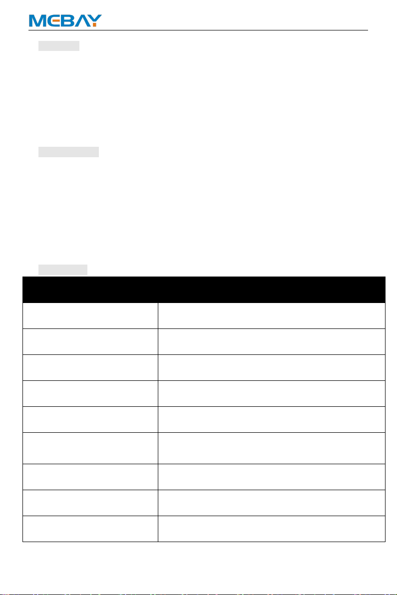
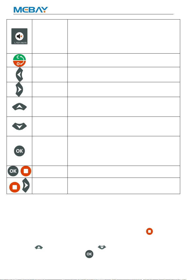
Test if all LED lights are ok, pressing this key to test if all
lighted, all off when loosen it.
Under warning, pressing this key can clear warning and
controller will re-check warning.
Under alarm, pressing this key can clear the buzzer call.
Pressing this key in 3 seconds can clear the buzzer call,
pressing it again in 3 seconds can recover the buzzer call.
Gens/ Mains
Close/On
Under manual mode, pressing this key can transfer load
to genset/mains.
Left
Under display mode, pressing this key to turn left page.
Under edition mode, pressing this key to move the digit.
Right
Under display mode, pressing this key to turn right page.
Under edition mode, pressing this key to move the digit.
Up
Under display mode, parts of the page can move up.
Under edition mode, pressing this key to move the digit
or increase the numbers.
Under records mode, pressing this key to move the digit.
Down
Under display mode, parts of the page can move down.
Under edition mode, pressing this key to move the digit
or decrease the numbers.
Under records mode, pressing this key to move the digit.
OK
Confirm the change under edition mode.
Page exited under records checking mode.
In the display mode, press to return to the display
homepage;
In standby state, press for 3 seconds to enter the
parameter setting mode.
+
Setting mode
Pressing OK and STOP simultaneously to come into
setting mode
+
Alarm
Records checking
Pressing STOP and RIGHT to check the records and
any buttons pressed to exit from the page.
Alarm records checking
HM500 controller can save 14 group of alarm records which contains the alarm
record data includes detailed data such as alarm time, generator parameters, engine
parameters, etc.
How to check the alarm records:
1)Enter alarm record page: In the standby state, press and hold the for more
than 3 seconds to enter the historical alarm recording interface;
2)Press to turn upper digit and press to turn lower digit in order to
choose the record you need. Press to confirm the record and come into
history records checking page.

HM500 DISPLAY PANEL OF GENERATOR CONTROLLER USER MANUAL
10
3)Press to turn lower records under records checking page. Press to
turn upper records and press to revert back to alarm history records page.
4)Exit from records page: In the history records page and checking page, press
to exit.
8. Control and operation instruction
Manual test mode:
press and make sure it is in the stop position before starting.
Press “ ” and the test file indicator is on. At this time, it is detected whether the
connection of each sensor is normal. If the sensor is open, the sensor opens an
alarm. If it is normal, the unit start process is executed in the following sequence after
pressing the " ". automatically switch to Generator provide the power when the unit
is running normally. Press “ ” The controller performs the parking process at the
following timing:
0RPM
Idle
Rated speed
Pre-
heat
delay
5S
Long-
est
pre-oil
supply
delay
0S
Start
Crank
delay
2S 8S
Safe
time
8S
Start
idle
time
5S
Longest
speed
increasing
time
120S
Idle
Rated speed
Pre-
heat
delay
Longest
temperature
increasing
time
10S
Longest
voltage
built/
increasing
time
120S 10S
rated
runn-
ing
Cooling
running time
30S
Stop
idle
time
5S
ETS
solen-
oid
hold
10S
Wait
Stop
30S
warming
up time
Crank
test
time
Manual Start Mode
press and make sure it is in the stop position before starting.
Press “ ” and the test file indicator is on. At this time, it is detected whether the
connection of each sensor is normal. If the sensor is open, the sensor opens an
alarm. If it is normal, the unit start process is executed in the following sequence after
pressing the " ". automatically switch to Generator provide the power when the unit
is running normally. Press “ ” The controller performs the parking process at the
following timing:
Manual start and stop process:

HM500 DISPLAY PANEL OF GENERATOR CONTROLLER USER MANUAL
11
0RPM
Idle
Rated speed
Pre-
heat
delay
5S
Long-
est
pre-oil
supply
delay
0S
Start
Crank
delay
2S 8S
Safe
time
8S
Start
idle
time
5S
Longest
speed
increasing
time
120S
Idle
Rated speed
Pre-
heat
delay
Longest
temperature
increasing
time
10S
Longest
voltage
built/
increasing
time
120S 10S
rated
runn-
ing
Cooling
running time
30S
Stop
idle
time
5S
ETS
solen-
oid
hold
10S
Wait
Stop
30S
warming
up time
Crank
test
time
After the manual start is successful, pressing the "automatic key" can be converted
into an automatic file. The specific working time is as follows:
0RPM
Idle
Rated speed
Pre-
heat
delay
5S
Long-
est
pre-oil
supply
delay
0S
Start
Crank
delay
2S 8S
Safe
time
8S
Start
idle
time
5S
Longest
speed
increasing
time
120S
Idle
Rated speed
Pre-
heat
delay
Longest
temperature
increasing
time
10S
Longest
voltage
built/
increasing
time
120S 10S
rated
runn-
ing
Transfer
back to
mains delay
10S
Cooling
running time
30S
Stop
idle
time
5S
ETS
solen-
oid
hold
10S
Wait
Stop
30S
warming
up time
Crank
test
time
Automatic starting mode:
press and make sure it is in the stop position before starting.
Press “ ” and the test file indicator is on. At this time, it is detected whether the
connection of each sensor is normal. If the sensor is open, the sensor opens an
alarm. If it is normal, wait for the remote start signal to be valid (detected the remote
starting signal is valid or the mains provide the power is invalid). The unit will perform
the starting process in the following sequence. When the unit enters the normal rated
operation, it will automatically switch to the generator provide the power. The
controller will detect the remote start signal and the mains status in real time. When
the remote start signal fails and the mains provide the power returns to normal, the
shutdown process after the "loop time delay" is performed.
Auto start and stop process:
Auto
Start
delay
0RPM
Idle
Rated speed
Pre-
heat
delay
5S 5S
Long-
est
pre-oil
supply
delay
0S
Start
Crank
delay
2S
Crank
test
time
8S
Crank
rest
time
10S 8S
Safe
time
8S
Start
idle
time
5S
Longest
speed
increasing
time
120S
Idle
Rated speed
Auto
Start
delay
Pre-
heat
delay
Longest
temperature
increasing
time
10S
Longest
voltage
built/
increasing
time
120S 10S
rated
runn-
ing
Transfer
back to
mains delay
10S
Cooling
running time
30S
Stop
idle
time
5S
ETS
solen-
oid
hold
10S
Wait
Stop
30S
warming
up time
Crank
test
time

HM500 DISPLAY PANEL OF GENERATOR CONTROLLER USER MANUAL
12
Notices in Starting Process
Note 1: During the Cranking time, the controller automatically detects the speed
signal, frequency signal and oil pressure value or the charging voltage (according to
the parameter setting) to reach the judgment condition of successful start, then the
judgment is that the start is successful and the motor relay is closed.
Note 2: Within the safety delay, only respond to emergency stop, immediate
stop, over speed, over frequency, over voltage, ECU communication Failure, shutter
open abnormal, other alarms are not responded to.
Note 3: No response to alarm and warning of under speed, low frequency,
under voltage, over current, over power, non-balance of current, external instant
unloading shutdown, during start idle time.
Note 4: No response to low frequency, under voltage, over current non-balance
of current, external instant unloading shutdown and over power is required when
entering the RPM-up time.
Note 5: No response to low frequency, under voltage, over current non-balance
of current, external instant unloading shutdown and over power is required when
entering the temperature-up time.
Note 6: No response to low frequency, under voltage, over current non-balance
of current, external instant unloading shutdown and over power is required when
entering the Voltage-up time.
Note 7: No response to low frequency, under voltage, over current non-balance
of current, external instant unloading shutdown and over power is required when
entering the Warming-up time.
Note 8: After entering rated operation, the Gens load relay output.
Note 9: In the process of shutdown, if the remote starting signal is restored to
be valid within the " Cooling time", the rated operation will be entered again.
Note 10: If the stop key is pressed again during idle time, the idle time will be
canceled and the stop operation will be executed directly.
9. Warnings and Shutdown Alarms
Warnings

HM500 DISPLAY PANEL OF GENERATOR CONTROLLER USER MANUAL
13
Notes: Warning is a non-serious failure state, which will not harm the gensets
system for the time being. It only reminds operators to pay attention to the situation
that does not meet the requirements and solve it in time to ensure the continuous
operation of the system. When the warning occurs, the gensets does not stop. Once
the fault is removed, the warning is automatically canceled.
Low Oil Pressure Sensor Warning
When the controller parameter "Action if low oil pressure" is set to "Warning" and
the programmable input port "Low oil pressure shutdown disabled" switch is valid,
and the controller detects that the engine Oil Pressure is lower than “Low oil
pressure warning”, Then start warning delay and the duration (Normal alarm delay)
have not returned to normal, the warning of low Oil Pressure is reported.
"WARNING" lights will light up, Generators will not stop, displays "Low OP sensor "
on the current fault screen.
Low oil Pressure switch warning
When the controller detects that the programmable input "Low oil Pressure warning
input" switch is active, it starts warning delay and lasts for Normal alarm delay.
When the " Low oil Pressure warning input" switch is enabled, the engine low oil
level switch warning is reported. "WARNING" lights will light up, Generators will not
stop, displays " Low oil pressure switch " on the current fault screen.
High temperature sensor warning
When the controller parameter "Action if high water temperature" is set to
"Warning" and the programmable input port "High water temperature disabled"
switch is valid, and the controller detects that the coolant temperature value is higher
than the "High coolant temperature warning", Then start warning delay and the
duration (Normal alarm delay) have not returned to normal, the warning of High
coolant temperature warning is reported. "WARNING" lights will light up, Generators
will not stop, displays " High temperature sensor " on the current fault screen.
High temperature switch warning
When the controller parameter "Action if high water temperature" is set to
"Warning" and the programmable input port "High temperature shutdown
disabled" switch is valid, and the controller detects that the oil temperature value is
higher than the "High temperature warning", Then start warning delay and the
duration (Normal alarm delay) have not returned to normal, the warning of High oil
temperature warning is reported. "WARNING" lights will light up, Generators will not
stop, displays " High temperature switch " on the current fault screen.
Low fuel level sensor warning
When the controller detects that the fuel level value is lower than the "Low fuel level
warning", Then start warning delay and the duration (Normal alarm delay) have not
returned to normal, the warning of Low fuel level warning is reported. "WARNING"
lights will light up, Generators will not stop, displays "Low fuel level-A" on the current
fault screen.
Low fuel level switch warning

HM500 DISPLAY PANEL OF GENERATOR CONTROLLER USER MANUAL
14
When the controller detects that the programmable input "Low fuel level warning
input" switch is active, it starts warning delay and lasts for Normal alarm delay.
When the "Low fuel level warning input" switch is enabled, the engine low fuel
level switch warning is reported. "WARNING" lights will light up, Generators will not
stop, displays "Low fuel level-D" on the current fault screen.
External instant warning
When the controller detects that the programmable input "External instant warning
input" switch is active, it starts warning delay and lasts for Normal alarm delay.
When the "External instant warning input" switch is enabled, the warning is
reported. "WARNING" lights will light up, Generators will not stop, displays "Instant
warn" on the current fault screen.
Speed signal lost warning
When the controller parameter "Action if RPM lost" is set to "warning", the detected
speed value is 0, Then start warning delay and the duration (Normal alarm delay)
have not returned to normal, the warning of speed signal lost warning is reported.
"WARNING" lights will light up, Generators will not stop, displays "Lose speed" on
the current fault screen.
Oil pressure sensor disconnected warning
When the controller parameter "Action if low oil pressure sensor disconnected" is
set to "warning", When the oil pressure sensor is detected to be disconnected, Then
start warning delay and the duration (Normal alarm delay) have not returned to
normal, the warning of Oil pressure sensor disconnected warning is reported.
"WARNING" lights will light up, Generators will not stop, displays " Oil pressure
sensor open" on the current fault screen.
Temperature sensor disconnected warning
When the controller parameter "Action if water temperature sensor disconnected"
is set to "warning", When the coolant temperature sensor is detected to be
disconnected, Then start warning delay and the duration (Normal alarm delay) have
not returned to normal, the warning of coolant temperature sensor disconnected
warning is reported. "WARNING" lights will light up, Generators will not stop, displays
"Temperature sensor open " on the current fault screen.
Fuel Level sensor disconnected warning
When the controller parameter "Action if fuel Level sensor disconnected " is set to
"warning", When the fuel Level sensor is detected to be disconnected, Then start
warning delay and the duration (Normal alarm delay) have not returned to normal, the
warning of fuel Level sensor disconnected warning is reported. "WARNING" lights
will light up, Generators will not stop, displays "Fuel Level sensor open" on the
current fault screen.
Maintenance expiration warning
When the controller parameter "Primary maintenance expire" is set to "warning",
when the primary countdown to maintenance is detected as "0" or primary
maintenance date less than current date, then start warning delay and the duration
(normal alarm delay), the warning of maintenance expiration is reported. "ALARM"
lights on, without stopping the engine, and displays " maintain end" on the LCD

HM500 DISPLAY PANEL OF GENERATOR CONTROLLER USER MANUAL
15
screen.
ECU faults warning
When the controller detects the warning information of ECU, Then start warning
delay and the duration (Normal alarm delay) have not returned to normal, the warning
of ECU faults warning is reported. "WARNING" lights will light up, Generators will not
stop, displays "ECU faults warn" on the current fault screen.
ECU Communication Failure Warning
When the controller parameter "CAN failure" is set to "warning", and controller
does not receive any message sent by ECU. It started to delay and lasted for some
time (Normal alarm delay) but still did not receive the message from ECU, the
warning of ECU faults warning is reported. "WARNING" lights will light up,
Generators will not stop, displays "ECU comm. fail" on the current fault screen.
Low coolant level switch warning
When the controller detects that the programmable input "Low water level warning"
switch is active, it starts warning delay and lasts for Normal alarm delay. When the
"Low water level warning" switch is enabled, the engine low coolant level switch
warning is reported. "WARNING" lights will light up, Generators will not stop, displays
"Low water level" on the current fault screen.
Over battery voltage warning
When the controller detects that the battery voltage is over than the "Over battery
voltage warning", Then start warning delay and the duration (Normal alarm delay)
have not returned to normal, the warning of over battery voltage warning is reported.
"WARNING" lights will light up, Generators will not stop, displays "Over BATT volt"
on the current fault screen.
Under battery voltage warning
When the controller detects that the battery voltage is lower than the "Under battery
voltage warning", Then start warning delay and the duration (Normal alarm delay)
have not returned to normal, the warning of Under battery voltage warning is reported.
"WARNING" lights will light up, Generators will not stop, displays "Under BATT volt"
on the current fault screen.
Charging failure warning
When the gap between D+ and B+ is over than this value, and there is charging
failure but still high (normal warning delay), then charge failure warns. "WARNING"
lights will light up, Generators will not stop, displays "Charger fault" on the current
fault screen. Once the gap is lower than the value, warns clear.
Starting fault
Fail to Start
If the number of cranks exceeds the predetermined number of cranks, the failure of
start-up will be reported if the start-up of the generating unit is still unsuccessful.
"ALARM" lights on, without stopping the engine, and displays " Crank failure " on
the current fault screen.

HM500 DISPLAY PANEL OF GENERATOR CONTROLLER USER MANUAL
16
Shutdown Alarms
Communication failure
When the controller detects that the display panel communication with FM7000 is
disconnected, the alarm delay starts and the communication failure with the display
panel continues for 20S, and then reports the failure of the main control board
communication failure, and the general alarm light "ALARM" indicator flashes
continuously, The device stops running and displays "Alarm: Communication
failure " on the current fault screen.
Over Speed Alarm
When the controller detects that the engine speed is higher than “Over speed alarm”,
Then start alarm delay and the duration (Emergency delay) have not lower than”Over
speed revert”, the alarm of over speed is reported. "ALARM" lights will light up,
Generator stops running, and displays " Over speed " on the current fault screen.
Under Speed Alarm
When the controller detects that the engine speed is under than “Under speed
alarm”, Then start alarm delay and the duration (Normal alarm delay) have not higher
than ”Under speed revert”, the alarm of under speed is reported. "ALARM" lights
will light up, Generator stops running, and displays " Under speed " on the current
fault screen.
Low Oil Pressure Sensor Alarm
When the controller detects that the engine Oil Pressure is lower than “Low oil
pressure alarm”, Then start alarm delay and the duration (Normal alarm delay) have
not returned to normal, the alarm of low Oil Pressure is reported. "ALARM" lights will
light up, Generator stops running, and displays "Low Oil Pressure sensor" on the
current fault screen.
Low oil pressure switch alarm
When the controller detects that the programmable input port "Low oil pressure
alarm input" switch is active. Start low oil pressure switch alarm delay, for a period
of time "Normal alarm delay" programmable input port "low oil pressure alarm
input" switch is valid. Then the alarm, the public alarm light "ALARM" lights will light
up, stop the unit operation, and display "Low oil pressure switch" on the current
fault screen.
High temperature sensor alarm
When the controller detects that the coolant temperature value is higher than the
"High coolant temperature alarm", Then start alarm delay and the duration (Normal
alarm delay) have not returned to normal, the alarm of High coolant temperature
alarm is reported. "ALARM" lights will light up, Generator stops running, and displays
"High temperature sensor" on the current fault screen.
High temperature switch alarm

HM500 DISPLAY PANEL OF GENERATOR CONTROLLER USER MANUAL
17
When the controller detects that the programmable input port "High temperature
alarm switch" switch is active. Start low oil pressure switch alarm delay, for a period
of time "Normal alarm delay" programmable input port "High temperature alarm
switch" is valid. Then the alarm, the public alarm light "ALARM" lights will light up,
stop the unit operation, and display " High temperature switch " on the current fault
screen.
Low fuel level sensor alarm
When the controller detects that the fuel level value is lower than the "Low fuel level
alarm", Then start alarm delay and the duration (Normal alarm delay) have not
returned to normal, the alarm of Low fuel level alarm is reported. "ALARM" lights will
light up, Generator stops running, and displays "Low fuel level sensor" on the
current fault screen.
Low fuel level switch alarm
When the controller detects that the programmable input "Low fuel level alarm
input" switch is active, it starts alarm delay and lasts for Normal alarm delay. When
the "Low fuel level alarm input" switch is enabled, the engine low fuel level switch
alarm is reported. "ALARM" lights will light up, Generator stops running, and displays
"Low fuel level switch" on the current fault screen.
External instant alarm
When the controller detects that the “External instant alarm input” switch of the
programmable input port is valid, the external instant trip is started and the shutdown
alarm delay is delayed for a period of time “Normal alarm delay” programmable
input port “External instant alarm input” switch When it is valid, it will alarm, the
public alarm light "ALARM" lights will light up, Generator stops running, and display
"Instant parking" on the current fault screen.
Speed signal lost alarm
When the controller parameter "Action if RPM lost" is set to "alarm", the detected
speed value is 0, Then start alarm delay and the duration (Normal alarm delay) have
not returned to normal, the alarm of speed signal lost warning is reported. "ALARM"
lights will light up, Generator stops running, displays "Lose speed" on the current
fault screen.
Oil pressure sensor disconnected alarm
When the controller parameter "Action if low oil pressure sensor disconnected" is
set to "alarm", When the oil pressure sensor is detected to be disconnected, Then
start alarm delay and the duration (Normal alarm delay) have not returned to normal,
the alarm of Oil pressure sensor disconnected alarm is reported. "ALARM" lights will
light up, Generator stops running, displays "Oil pressure sensor open" on the
current fault screen.
Temperature sensor disconnected alarm
When the controller parameter "Action if water temperature sensor disconnected"
is set to "alarm", When the coolant temperature sensor is detected to be
disconnected, Then start alarm delay and the duration (Normal alarm delay) have not
returned to normal, the alarm of coolant temperature sensor disconnected alarm is
reported. "ALARM" lights will light up, Generator stops running, displays "

HM500 DISPLAY PANEL OF GENERATOR CONTROLLER USER MANUAL
18
Temperature sensor open" on the current fault screen.
Fuel Level sensor disconnected alarm
When the controller parameter "Action if fuel Level sensor disconnected " is set to
"alarm", When the fuel Level sensor is detected to be disconnected, Then start alarm
delay and the duration (Normal alarm delay) have not returned to normal, the alarm
of fuel Level sensor disconnected alarm is reported. "ALARM" lights will light up,
Generator stops running, displays " Fuel Level open" on the current fault screen.
Over frequency alarm
When the controller detects that the generator frequency is higher than “Over
frequency alarm”, Then start alarm delay and the duration (Emergency delay) have
not returned to normal, the alarm of over frequency is reported. "ALARM" lights will
light up, Generator stops running, displays " Over frequency " on the current fault
screen.
Under frequency alarm
When the controller detects that the generator frequency is lower than “Under
frequency alarm”, Then start alarm delay and the duration (Normal alarm delay)
have not returned to normal, the alarm of under frequency is reported. "ALARM"
lights will light up, Generator stops running, displays " Under frequency " on the
current fault screen
Over voltage alarm
When the controller detects that the generator voltage is higher than “Over voltage
alarm”, Then start alarm delay and the duration (Normal alarm delay) have not
returned to normal, the alarm of over voltage is reported. "ALARM" lights will light up,
Generator stops running, displays " Over voltage " on the current fault screen.
Under voltage alarm
When the controller detects that the generator voltage is lower than “Under voltage
alarm”, Then start alarm delay and the duration (Normal alarm delay) have not
returned to normal, the alarm of under voltage is reported. "ALARM" lights will light
up, Generator stops running, displays " Under voltage " on the current fault screen.
Over current alarm
When the controller detects that the generator phase current is higher than “Phase
current over-load alarm”, Then start alarm delay and the duration (Normal alarm
delay) have not returned to normal, the alarm of over current is reported. "ALARM"
lights will light up, Generator stops running, displays " Over current " on the current
fault screen.
Non-balance current ratio alarm
When the controller is t2 phase 3 wire or 3 phase 4 wire, the controller detects that
the unbalance degree of the three-phase or two-phase current of the generator is
higher than the "Non-balance current ratio alarm". Then start alarm delay and the

HM500 DISPLAY PANEL OF GENERATOR CONTROLLER USER MANUAL
19
duration (Normal alarm delay) have not returned to normal, the alarm of Non-balance
current ratio is reported. "ALARM" lights will light up, Generator stops running,
displays " Unbalance of AMP " on the current fault screen.
Over power alarm
When the controller detects that the generator power is higher than “Over total
power alarm”, Then start alarm delay and the duration (Normal alarm delay) have
not returned to normal, the alarm of over power is reported. "ALARM" lights will light
up, Generator stops running, displays " Over power " on the current fault screen.
Generator loading failure
When the controller parameter "Gens breaker checking" is set to "alarm", When the
ATS switch is switched, it is detected that the programmable input switch of "Gens
un/loading input" is invalid. Then start alarm delay and the duration (Normal alarm
delay) have not returned to normal, the alarm of generator loading failure is reported.
"ALARM" lights will light up, Generator stops running, displays " Gens onload fail "
on the current fault screen.
Maintenance expiration alarm
When the controller parameter "Primary maintenance expire" is set to "alarm",
when the primary countdown to maintenance is detected as "0" or primary
maintenance date less than current date, then start alarm delay and the duration
(normal alarm delay), the alarm of maintenance expiration is reported. "ALARM"
lights on, without stopping the engine, and displays " Maintain end" on the LCD
screen.
ECU faults alarm
When the controller detects the alarm information of ECU, Then start alarm delay and
the duration (Normal alarm delay) have not returned to normal, the alarm of ECU
faults alarm is reported. "ALARM" lights will light up, Generator stops running,
displays "ECU faults warn" on the current fault screen.
ECU communication failure alarm
When the controller parameter "CAN failure" is set to "alarm", and controller does
not receive any message sent by ECU. It started to delay and lasted for some time
(Normal alarm delay) but still did not receive the message from ECU, the alarm of
ECU faults alarm is reported. "ALARM" lights will light up, Generator stops running,
displays "ECU comm. fail" on the current fault screen.
Low water level switch alarm
When the controller detects that the programmable input "Low water level alarm"
switch is active, it starts alarm delay and lasts for Normal alarm delay. When the
"Low water level alarm" switch is enabled, the engine low coolant level switch
alarm is reported. "ALARM" lights will light up, Generator stops running, displays
"Low water level" on the current fault screen.
Louver opening exception alarm
When the controller detects that the programmable input "Louver status input"
switch is active, it starts alarm delay and lasts for Normal alarm delay. When the
Table of contents