MECHAPRO Slider SFX User manual

Manual Slider SFX Page 1
All in one
stepper motor driver
Slider SFX
Control factory automation
machinery and
CNC machine tools
by use of stepper motors
© Copyright mechapro GmbH, 2010

Page 2 Manual Slider SFX
The present stepper motor driver board was developed taking all common and established
rules into account. It has undergone extremely thorough testing. Nevertheless, it is impos-
sible to give a guarantee for completely fault-free operation. Furthermore, no responsibility
can be accepted for damage caused as a result of using Slider SFX. The developers ensu-
re that Slider SFX in combination with appropriate controls and appropriate mechanical
components for the purpose of this description and manual is in principle appropriate for
the intended use.
Each liability for associated consequential losses, such as loss of use, production and loss
of profits is excluded. Slider SFX is a component that can only be used together with a
power supply and an adequate control or control software on a personal computer. It is no
independent control under any circumstances.
Despite the most strenuous efforts, it is never possible to completely eliminate all faults.
Consequently, we would be grateful to receive feedback from users.
mechapro GmbH
Roermonder Str. 63
52134 Herzogenrath
Tel.: 0241/4091800
Fax: 0241/4091803
March 2013
All products mentioned by name are trademarks or registered trademarks of their corre-
sponding companies.

Manual Slider SFX Page 3
The structure of this manual…
This manual provides you with all information necessary to use your Slider SFX. It is divi-
ded into different chapters, the contents of which are summarised below:
Chapter 1: Short introduction and technical details
Chapter 2: Procedure for initial operation, pin out
Chapter 3: Safety instructions
Table of content
1 What is Slider SFX used for?...........................................................................4
1.1 Versions of Slider SFX.....................................................................................5
1.2 Optional 4th axis............................................................................................6
2 Start of operation........................................................................................... 7
2.1 Base settings on delivery ................................................................................8
2.2 Mounting and ventilation...............................................................................8
2.3 Mounting dimensions ....................................................................................9
2.4 X4 – Power supply .........................................................................................9
2.5 X10 – Control signals..................................................................................... 10
2.6 JP1-JP8 – Jumper settings, signal assignment.................................................. 11
2.7 JP6 – Pin14 drives relay 2 or PWM logic.......................................................... 12
2.8 JP10 – Toggle signal, safety function ..............................................................12
2.9 JP11 – Start up time ......................................................................................13
2.10 JP12 – Invert relay signals............................................................................... 13
2.11 X3(1/2) – Emergency stop ..............................................................................13
2.12 X7 – Inputs for limit and reference switches ................................................... 14
2.13 X2 – Switching outputs.................................................................................. 14
2.14 X3(3/4) – Analogue output signal for spindle control......................................15
2.15 X6, X8, X11 – Motor connectors.................................................................... 16
2.16 X5 – Additional capacitor............................................................................... 17
2.17 S1/S2/S3/S5 – Setup of motor current and step width ....................................17
2.18 LED’s / status signals.......................................................................................18
2.15 X13 – Connector for external LED’s................................................................19
2.20 X1 – Fan connector........................................................................................ 19
2.21 X9/X14 – Extension for 4th axis......................................................................20
3 Safety instructions..........................................................................................22
Page 4 Manual Slider SFX
1 What is Slider SFX used for?
The stepper motor driver Slider SFX is a sophisticated circuit, which includes power drivers
for three or four 2-phase stepping motors and some other useful components. The signals
to drive the board are connected to a 25-pin D-Sub type female connector, which can be
driven by appropriate controls or directly by a LPT printer port of a personal computer with
appropriate control software.
Slider SFX can be used ideally with the software products PC-NC and WinPC-NC that are
also available on our shop. The signals are fully compatible to these control programs.
A three or four axes mechanic can be used for a wide range of applications. Some examp-
les are….
• Engraving signs
• Milling 3D reliefs
• Milling negative matrices and casting moulds
• Cutting sticky foils
• Milling and drilling prototype PCBs
• Apply and dispense glues
• Cut and machine front plates
• Turning and shaping
• Gas and Plasma cutting
• Pick&Place or robot applications
• ...and many more

Manual Slider SFX Page 5
The technical data of the Slider SFX board are...
• Connection of three 2-phase stepping motors direct on the board
• Optional 4th axis as a plug-in board
• Single supply with AC or DC voltage without external stabilisation, meaning easy
supply with a transformer
• Control signals via 25-pin D-Sub type connector (female), e.g. directly from a PC prin-
ter port (LPT)
• Full-, half-, quarter, 8th- to 16th-step, 2.5th to 10th-step also possible (sinusoidal
micro step)
• Phase current up to 3.0A
• Individual setup of phase current for each axis with DIP switches, additional current
reduction input (reducing current to 50%)
• Protected against short windings and shorts to ground
• Ready switch acts as enable signal directly to power stages and relays, can be used
e.g. on a protection hood
• Three relays (240V~/10A) for switching outputs, e.g. main spindle, coolant pump,
chuck etc., also capable of switching DC current
• LED’s to signal supply voltage and other states, additional connector makes it possible
to integrate LED’s into front plate of housing etc.
• 5 free assignable inputs (N.O. or N.C. contacts), e.g. for limit or reference switches
• Protection circuit with toggle or ready signal to disable motors and relays
• Connector for additional 4th axis
• Standard version for ambient temperatures up to 50°C, special HT version for ambi-
ent temperatures of up to 70°C
• Analogue output 0-5V or 0-10V to drive speed controlled milling/drilling spindles,
interpretation of a PWM signal
• Control of a relay depending on PWM value, threshold level 10%
• Emergency signal, N.C. contact
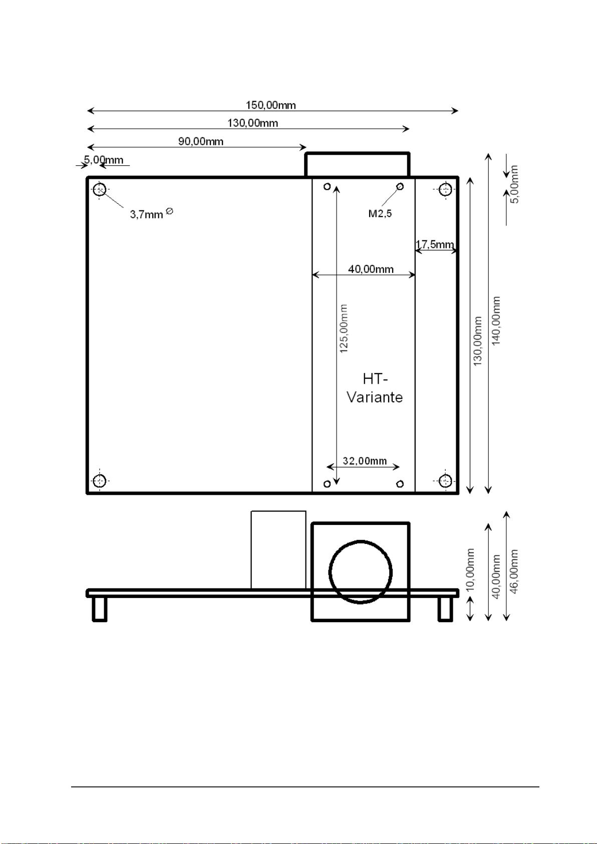
• Dimensions: 150*130*52mm
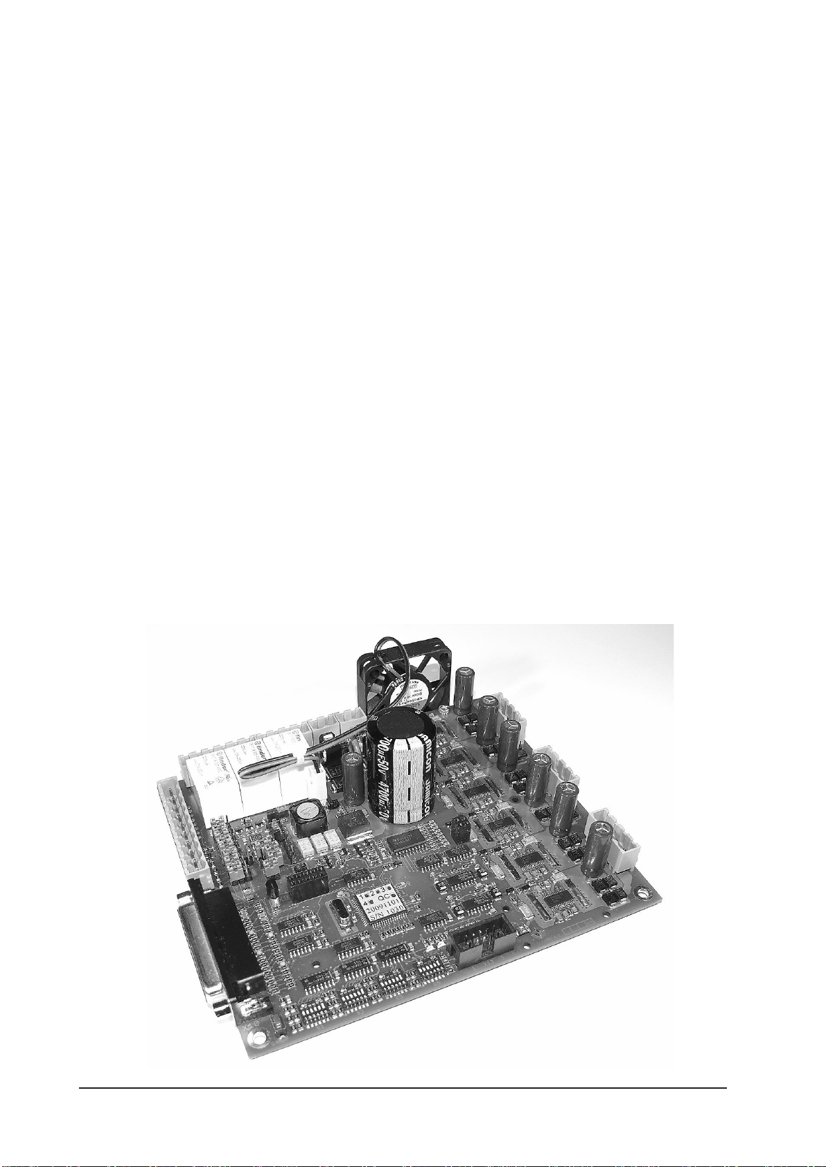
1.1 Versions of Slider SFX
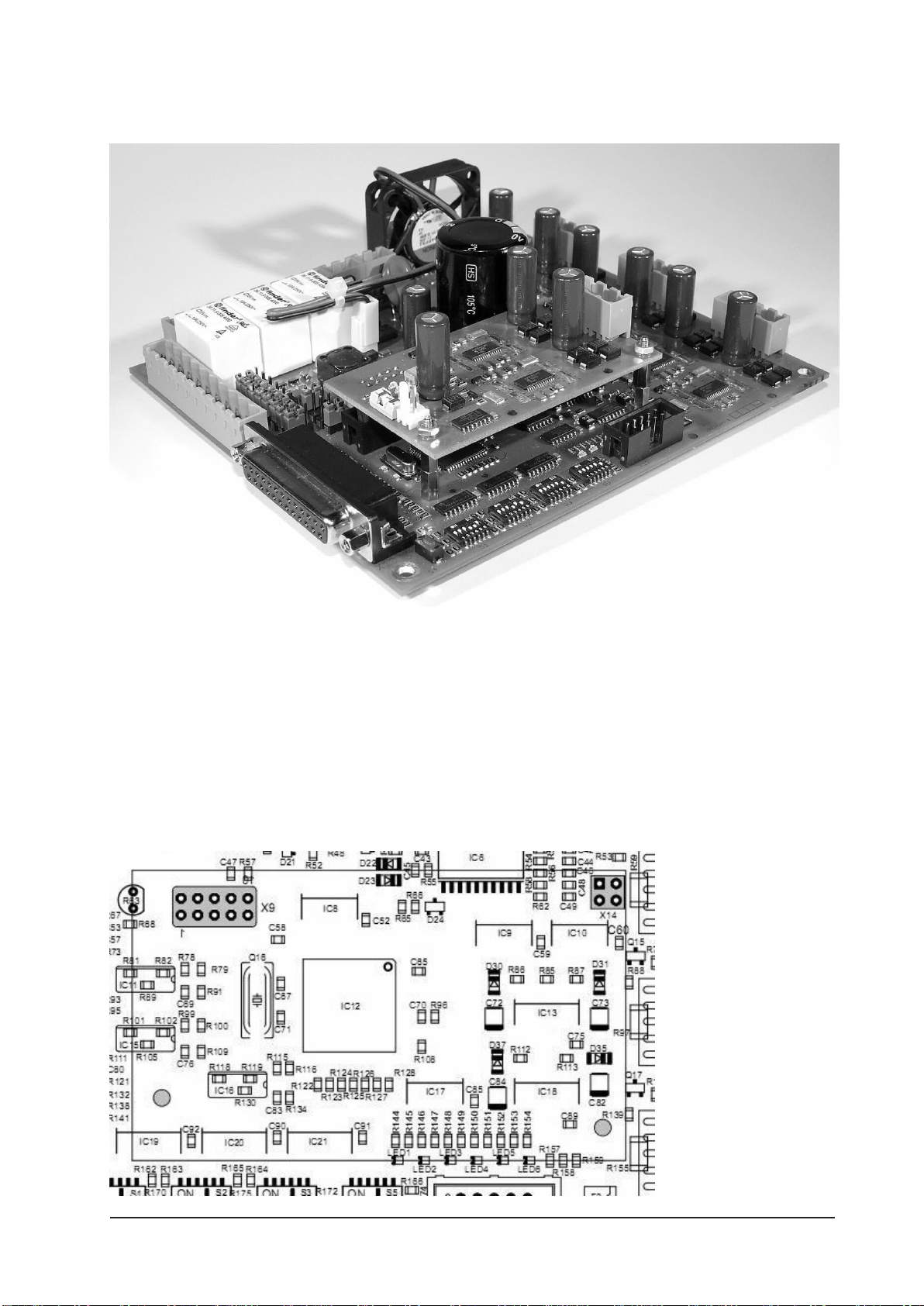
The stepper motor driver Slider SFX is available in two versions and with optional 4th axis.
The standard version is designed for ambient temperatures up to 50°C and has to be used
in housings and machines where this ma-
ximum temperature is not exceeded. A fan
mounted to the side of the board or a case
fan ensures proper cooling. A filter with 30
ppi or higher is required.
The version Slider SFX HT is designed for
ambient temperatures up to 70°C and is
equipped with passive heat sinks on both
top and bottom side. A fan should be
used in a similar way than on the standard
version.
Page 6 Manual Slider SFX
Although the drivers are protected by an excess temperature protection, proper cooling has
to be clarified with the manufacturer.
Special fan less OEM versions or with other special and customer specific options can be
supplied on demand. We are looking forward to your requests.
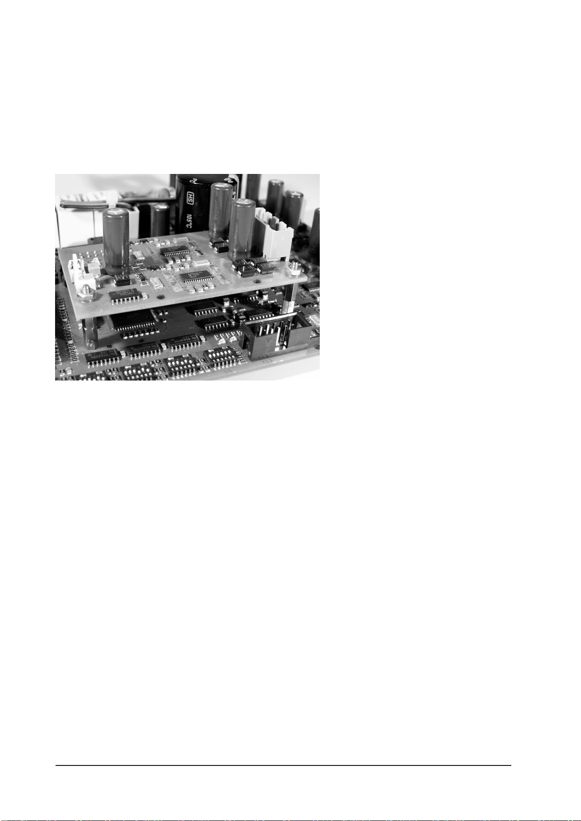
1.2 Optional 4th axis
With an addon board, SliderSFX is
capable of driving 4 axies. The plug-
in position with two connectors and
mounting holes is placed directly
abouve the DIP switches.
The add-on moduleSliderSFX-4
can be ordered together with the
main board or later as a single part
including mounting material. It can
be easily installed by the user.
Manual Slider SFX Page 7
2 Start of operation
Please make sure to follow all protective regulations before the first initial operation of the
board and before connecting or switching on the supply voltage.
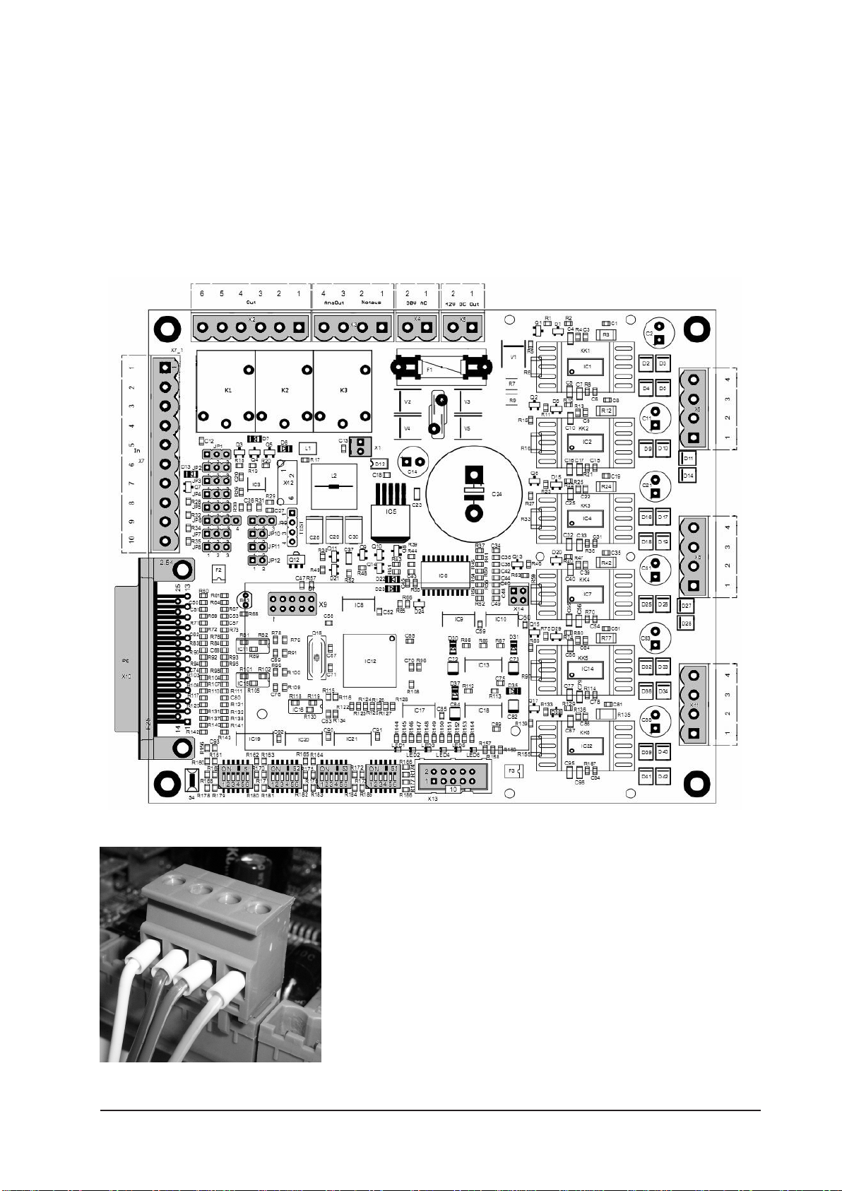
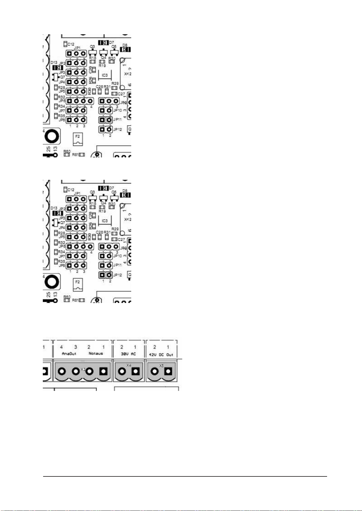
On the Slider SFX board all connections are equipped with pluggable cage clamps. All
connectors will be described in the following sections. The sketch gives a first overview. All
relevant connections and settings are marked in grey.
On all connections care should be taken to achieve the
best possible contact. All signal and motor wires should be
be equipped with core cable ends. To avoid disturbances
especially on the switch inputs on X7, shielded and/or
twisted pair wires have to be used.

Page 8 Manual Slider SFX
2.1 Base settings on delivery
The board is shipped in a base setting, were all jumper are set to position 1-2, JP10 and
JP11 are open, JP12 is closed. This results in the following functional assignment on the
interface X10 (input from the parallel port of a PC):
Pin 14 switches relay 2
Pin 15 is general input
Pin 16 switches relay 3
Pin 17 controls the current reduction of the motors (low active)
For a complete description of the interface X10 please refer to section 2.5.
The voltage range on the analogue output (to control a main spindle) is set to 0-10V. The
monitoring of the toggle signal is disabled. Relays are not inverted and the start up time is
aprox. 3 seconds.
The DIP switches are set in a way that all motors are driven with 1.0A and in quarter step
mode, meaning with 800 steps/rev for a standard 1.8° motor.
2.2 Mounting and ventilation
Slider SFX is tested for ambient temperatures of up to 50°C. An HT version is available
for ambient temperatures of up to 70°C. When mounting the board into a case, sufficient
ventilation has to be provided, e.g. by placing adequate ventilation slots in the case hood.
The fan that is mounted on the side of the Slider SFX board can be used on both sides of
the board, according to assembly and ventilation in the case. If a case with integrated fan
is used, the air stream should pass the 6 drivers (IC’s 1, 2, 5, 7, 12 and 17). The direction of
the board’s fan air stream should be adjusted in the same direction as the case fan. If the
ventilation of the case is sufficient, the fan on the board might be redundant.
Warning:
Ventilations slots (for active or passive cooling) should be covered with filter pads
of at least 30 ppi to protect them against intrusion of chips. Intruding chips and
metal parts can influence the function of the board and may also completely dest-
roy it!
The HT version for ambient temperatures up to 70°C is equipped with a 10mm thick alu-
minium heat sink on the bottom side. This heat sink has to be mounted to the bottom
plate of the case with its full surface. This ensures optimal heat conduction.
Manual Slider SFX Page 9
2.3 Mounting dimensions
2.4 X4 – Power supply
The stepper motor board Slider SFX can be supplied with either AC or DC voltage. When
using AC power, the lower threshold is 12V~ while the upper threshold is 30V~. For DC
power the thresholds are 15V= and 42V=, the polarity is irrelevant. The supply input is pro-
tected by a glass fuse (6.3A fast blow). Blown fuses must always be replaced by the same
rated current and characteristic!

Page 10 Manual Slider SFX
We recommend a transformer or power
supply rating of 100VA to 160VA, depen-
ding on the employed motors and the volta-
ge level of the supply. We would be happy
to give you an advice. To follow the EMC
regulations an adequate supply filter has to
be used in addition the transformer used in
your application.
Attention:
When decelerating a stepper motor acts as a generator. This causes the supply
voltage to increase. The voltage should not exceed 45V= to avoid damaging the
drivers. This danger is more likely with higher supply voltages.
2.5 X10 – Control signals
All control signals are feed in by the 25-pin female D-Sub type connector. The signals are
switched to ground and are designed in a way that also weak ports on modern computers
are able to drive them.
The pin out is...
Pin 1 Relay 1, e.g. main spindle on/off
Pin 2 Direction motor X
Pin 3 Clock motor X
Pin 4 Direction motor Y
Pin 5 Clock motor Y
Pin 6 Direction motor Z
Pin 7 Clock motor Z
Pin 8 Direction motor 4 (option) or relay 2
Pin 9 Clock motor 4 (option) or relay 3
Pin 10-13Forwarded inputs, e.g. for signals from limit and
reference switches
Pin 14 PWM signal or relay 2, e.g. coolant pump on/off
Pin 15 Output for ready signal or signal from limit
or reference switches
Pin 16 Toggle signal or relay 3, e.g. chuck for tool changer
Pin 17 Current reduction input (active low), toggle or PWM
signal
Pin 18-25Signal ground (0V, GND)
Together with our CNC control software PC-NC CNC-Control, WinPCNC and X4Step
there are no compatibility problems driving a 3 or 4 axes mechanic. Of course any other
software with pulse and direction output signals can be used.

Manual Slider SFX Page 11
2.6 JP1-JP8 – Jumper settings, signal assignment
Some pins (8, 9, 14, 16 and 17) on Slider SFX can be used for different functions. Section
2.5 gives an overview about all inputs and their functions. The settings are made with jum-
pers, while setting connection pins 1-2 is the standard stetting (except for JP10).
• JP1: Pin15 forwards general input (jumper 1-2) or outputs ready signal (low active)
of Slider SFX (jumper 2-3).
• JP4: Pin16 switches relay 3 (jumper 1-2) or drives toggle signal (jumper 2-3).
• JP6: Pin14 switches relay 2 (jumper 1-2) and/or drives PWM signal (jumper 3-4). To use
both functions, two jumpers are necessary.
• JP7: Pin8 switches direction of motor 4 (jumper 1-2) or switches relay 2 (jumper 2-3).
• JP8: Pin9 switches clock of motor 4 (jumper 1-2) or switches relay 3 (jumper 2-3).
To evaluate the ready signal with WinPCNC the signal “I247 NReady” has to be assigned
to Pin15.
The ready signal is disabled (meaning set to logic high) by Slider SFX when the contact X3
(emergency switch) is opened or when an error occurs on the board (e.g. shorted coil of a
motor). With this signal is can be avoided that the board continues operation after clearing
an error, although the position of the motors doesn’t comply with the position that is assu-
med by the CNC software.
Caution:
Never configure two pins for the same function, as
this may result in a short of the outputs on the printer
port. This concerns all jumper settings from JP2 to JP8.
To avoid damages by unintended touching of nearby
components, it is highly recommended to change jum-
per settings only when the board is powerd down.
Function of Pin17 JP2 JP3 JP5
Current reduction 1-2 1-2 Any
Toggle 2-3 2-3 1-2
PWM 2-3 2-3 2-3
When using WinPCNC with the current reduction signal on Pin17, Signal “Q251 axis run-
ning” has to be set to “Pin 17 inverted”.

Page 12 Manual Slider SFX
2.7 JP6 – Pin14 drives relay 2 or PWM logic
Jumper JP6 is intended as a double contact and selects two
functions.
If set to position 3-4, the signal coming from Pin14 is fed
to the PWM logic and converted to an analogue signal
with 0-5V or 0-10V range. If a jumper is set to position 1-2,
Pin14 controls relay 2. When both jumpers are set, Pin14 is
fed to the PWM logic and relay 2 is switched automatically
depending on the PWM value.
The threshold includes a hysteresis of aprox. 5%. At PWM
values higher than 10%, the relay is switched on. When
the PWM value falls under 5%, the relay is switched of
again.
• Jumper JP6 set to 1-2 only Pin 14 controls relay 2
• Jumper JP6 set to 3-4 only Pin 14 controls PWM logic which outputs the analogue
value
• Jumper JP6 set to both 1-2 and 3-4 Pin 14 controls PWM logic and relay 2 is switched
depending on PWM value.
2.8 JP10 – Toggle signal, safety function
On power up and caused by plug&play routines of the
operating system, the pins on the parallel port may change
their logic levels before the port is under control of the CNC
software (e.g. WinPCNC). To prevent unintended switching
of relays and unintended movements of the motors, Win-
PCNC supports the output of a safety signal (“Q219 Toggle/
Ready”). In other products this is sometimes referred to as
“charge pump signal”. If enabled, Slider SFX will enable
relays and motors only when a valid toggle signal (minimum
frequency of 250 Hz) is recognised.
When using a control software that doesn’t support this
signal, e.g. PCNC (DOS), the monitoring of this signal has to
be disabled by setting JP10 open (default setting).
• JP10: Toggle signal monitored (jumper closed) or not (jumper open).
Manual Slider SFX Page 13
2.9 JP11 – Start up time
Jumper JP11 influences the start up time of the board.
When the jumper is left open, it takes aprox. 3 seconds after
power on until the board is ready and the motors are under
current. With JP11 set, this time is extended to aprox. 10
seconds. This may help to ensure, that the primary control or
the PC with control software is ready and all signals are in a
defined condition.
On each boot up, the board signals the version number of
the firmware on LED1, before ready is indicated.
• JP11: Start up time 3 seconds (jumper open) or
10 seconds (jumper closed)
2.10 JP12 – Invert relay signals
Depending on the signal level to control the relays, it may
be, that the behaviour of the relays is inverted compared to
the driving logic. Additionally, during power on or boot up
of the PC the relays may be switched unintended. With JP12
closed, the control signals for all three relays are inverted.
• JP 12: Relay control signals inverted (jumper closed) or
normal (jumper open).
2.11 X3(1/2) – Emergency stop
The ready or emergency signal on clamp
X3, contacts 1/2, activates the three power
drivers for the motors and also acts as ena-
ble signal for the relays. The signal is routed
to the enable input of the power drivers
and can therefore be used as an emergency
signal or as a contact of a protection hood.
The switch has to be an N.C. contact. With the contact opened, all three motors are cur-
rent less and can not be driven by the board. Same applies for the relays.
Caution:
Current less motors do have a very small holding toque. If they are in motion, they
continue running due to the inertia of the axis. A current less Z-axis may fall down
on the table or to the mechanical limit due to its mass.

Page 14 Manual Slider SFX
If no switch is used, the contact must be closed by a wire strap to ensure proper operation
of the board.
Pin out on X3:
Pin 1 Emergency contact
Pin 2 GND
2.12 X7 – Inputs for limit and reference switches
The stepper motor board Slider SFX has 5 inputs that are forwar-
ded to signals on the 25 pin D-Sub type connector. These are ex-
actly the signals, which are used as inputs on the PC parallel port.
Switches with both N.O. or N.C. can be used. For each input, two
cage clamp contacts are present.
The pin out is as follows...
• Clamp X7.1 Pin 10
• Clamp X7.2 GND
• Clamp X7.3 Pin 11
• Clamp X7.4 GND
• Clamp X7.5 Pin 12
• Clamp X7.6 GND
• Clamp X7.7 Pin 13
• Clamp X7.8 GND
• Clamp X7.9 Pin 15
• Clamp X7.10 GND
Depending on the interpretation in the control or in the control
software, these inputs can be used for limit switches, reference
switches or other sensors.
Please note:
Depending on setting of JP1, Pin 15 forwards input X7.9 or signals the operational
status of the boards
2.13 X2 – Switching outputs
Slider SFX is equipped with 3 relays which are cont-
rolled over the 25-pin D-Sub type port. Depending on
the configuration of the board, the pins 1, 8, 9, 14
and 16 are possible inputs, which can be controlled
by PCNC or WinPCNC as outputs for main spindle,
coolant pump and chuck for tool changer or other
purposes.
The assignment between pins and relays is done with jumpers (see chapter 2.5).

Manual Slider SFX Page 15
The assignment is as follows...
• Clamp X2.1/2 relay 3 - pin 16 (alternative pin 9)
• Clamp X2.3/4 relay 2 - pin 14 (alternative pin 8)
• Clamp X2.5/6 relay 1 - pin 1
All relays can switch up to 10A at max. 240VAC. DC currents can be switched also.
2.14 X3(3/4) – Analogue output signal for spindle control
Slider SFX can convert a PWM input signal (min. PWM
frequency 200 Hz) to an analogue output signal. Many fre-
quency converters accept such a signal as reference value for
the rotational speed of synchronous or asynchronous main
spindle motors. Consult the manual of your converter to see
how the reference input has to be parameterised.
The output of Slider SFX supports either a signal range
from 0V to 10V (default setting) or from 0V to 5V, where 10V (or 5V respectively) equals
the maximum rotational speed. Pre-condition to use this feature is to select an input pin for
the PWM signal and a matching configuration of the control software, e.g. our Win-PCNC
(signal “Q218 rotational speed PWM”).
The PWM signal can be evaluated from pin 14 or pin 17. The mapping of the signals is
done by jumpers JP2, JP3, JP5 and JP6.
• JP9: analogue output (main spindle) 0-10V (jumper 1-2) or 0-5V (jumper 2-3).
Page 16 Manual Slider SFX
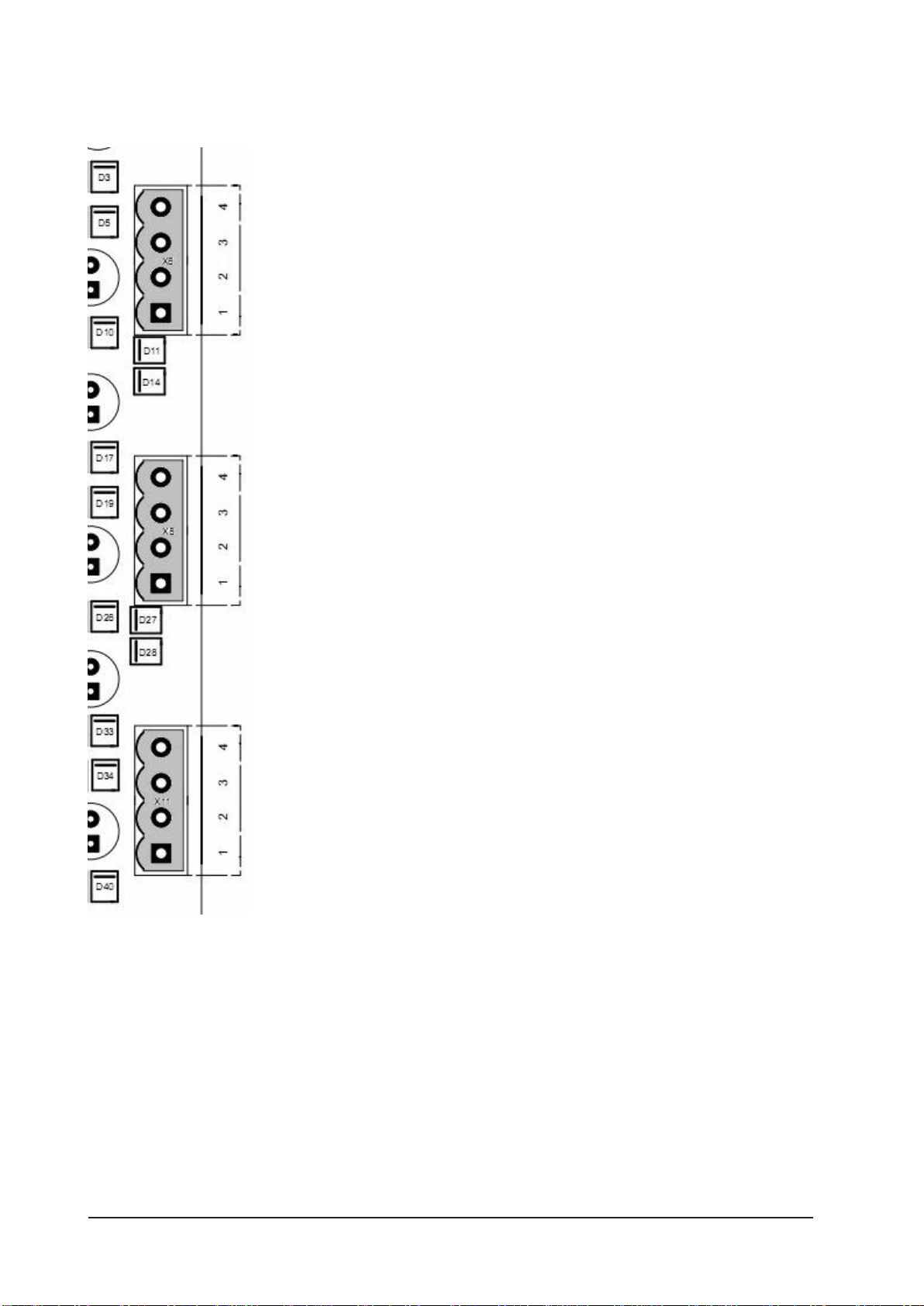
2.15 X6, X8, X11 – Motor connectors
Slider SFX is designed for 2-phase stepping motors only. It can
be used with both bipolar and unipolar motors. If no datasheet is
available to your motors, you have measure which connectors be-
long to which winding of the motor.
Bipolar motors have 4 connections, where each winding has two
connections. These can be found easily with an Ohm meter. Both
ends of one winding have to be connected to the board as phase
A1/A2, while the other one are connected as phase B1/B2.
Unipolar motors come with 5 or 6 connections, where both win-
dings have an additional contact in the middle of the coil. Also with
this motors, the endings of whe coils can be found easily by measu-
ring the resistance of the different connections. Leave the centre
taps unconnected and isolate them to prevent any contact with
conductive materials. The connection to the board is then the same
as before, connecting one coil to phase A1/A2, the other one to
phase B1/B2.
When the motor connections are correct, the motors should move
smooth and without jerk in both directions. A wrong connection
leads to jerky movement or in a dithering movement of the motor.
The direction of the motor’s movement can be changed by crossing
the connections on one of the phases, e.g. changing A1 with A2.
The connections are assigned as follows:
• X11 (1+2) – X axis phase A
• X11 (3+4) – X axis phase B
• X8 (1+2) – Y axis phase A
• X8 (3+4) – Y axis phase B
• X6 (1+2) – Z axis phase A
• X6 (3+4) – Z axis phase B
Attention:
Do not connect a motor phase to positive supply voltage under no circumstances.
This would inevitably lead to a break down of the power driver.

Manual Slider SFX Page 17
2.16 X5 – Additional capacitor
When decelerating, a stepper motor acts as
a generator and supplies current back to the
power supply. This will temporarily cause
the supply voltage to increase significantly.
To prevent rising above 45VDC, an electro-
lytic capacitor can be connected to clamp
X5 in addition to the capacitor in the pow-
er supply. Especially when using large and powerfull motors and high supply voltages, an
additional capacitor is recommended.
Assignment on X5:
Pin 1 GND
Pin 2 +42V
Please note:
In most circumstances, the use of an additional, external capacitor is not necessary.
2.17 S1/S2/S3/S5 – Setup of motor current and step width
The stepping motor drivers support mi-
crostep operation. They produce a sinu-
soidal course of motor currents. The step
width can be set individually for each
motor with the left three DIP switches
according to the following table.
Beside the dividers that are common for
2-phase motors down to 1/16th (3,200
steps per revolution) it is also possible to use dividers 1/2.5th to 1/10th commonly used
with 5-phase motors (500, 1,000 and 2,000 steps per rev.).
Furthermore the right three DIP switches are used to set the phase current of the power
drivers in 0.25A steps. In addition, pin 17 can be used to activate a current reduction down
to 50% of the selected set value. See section 2.5 for details. If clock pulses are applied to
the board with current reduction activated, the onboard controller will automatically disab-
le the current reduction until all steps are processed.
Changes on the DIP switches are taken over within less than 1 second without rebooting
the board. Changes to the step width may result in a position error of up to 4 full steps, so
it is recommended to do a reference movement after changing this setting.
The axes are allocated to the switches as follows:
• S1 – X axis
• S2 – Y axis
• S3 – Z axis
• S5 – optional 4th axis

Page 18 Manual Slider SFX
For each axis (n=1, 2, 3, 4) there exist 6 DIP switches. The switches Sn.1-n.3 are used for
setting the set value for the motor current, while the switches Sn.4-n.6 define the step
width according to the following tables:
Sn.1 Sn.2 Sn.3 Current
0 0 0 1.0 A (default setting)
0 0 1 1.5 A
0 1 0 1.75 A
0 1 1 2.0 A
1 0 0 2.25 A
1 0 1 2.5 A
1 1 0 2.75 A
1 1 1 3.0 A
Sn.4 Sn.5 Sn.6 Step width
0 0 0 ½
0 0 1 ¼ (default setting)
0 1 0 1/8
0 1 1 1/16
1 0 0 1/1
1 0 1 1/2,5
1 1 0 1/5
1 1 1 1/10
2.18 LED’s / status signals
There are some LED’s placed above the connector X13, that are used to signal the current
operating condition of the Slider SFX board.
LED1: Status indication
LED2: Toggle signal (safety function) recognised
LED3: Short detected, the blink code identifies the faulty axis
LED4: Shutdown due to over voltage
LED5: Power supply present
LED6: 5V (Logic supply) present
Explanation to the meaning of the LED’s:
LED1 signals errors on the board. A continuous, slow blinking LED signals that contact X3
(pins 1-2) was opened. A fast, 4-times blinking with following pause signals a short conditi-
on on one of the outputs.
LED2 shows, if a valid toggle signal was detected. If the evaluation of the toggle signal is
activated (JP10 set to 1-2), and LED7 is not lit (meaning no valid signal is applied to the
board), the drivers are switched of and the board is not ready.

Manual Slider SFX Page 19
LED3 signals a short on one of the axes and has to be cleared by the reset button S4. LED3
blinks once for a short on the X axis, twice for a short on the Y axis, three times for a short
on the Z axis. The blink code will be repeated after a short pause. For a fault on the optio-
nal 4th axis, LED3 is lit continuously.
If the supply voltage rises above 44V, the power supply shuts down the logic voltage
(5VDC), which leads to a shut down of the power stages. This is signalled by LED4.
2.15 X13 – Connector for external LED’s
If Slider SFX is mounted into a case, so that the on board LED’s can not be seen from the
outside, it is possible to connect some additional LED’s to connector X13, which then can
be mounted into the front plate of the case. The pinout of X13 is:
Pin 1 LED1, Status (Vcc)
Pin 2 VMotor (used for LED4)
Pin 3 LED4, over voltage (VMotor)
Pin 4 (not used)
Pin 5 LED5, motor supply voltage (GND)
Pin 6 LED3, short detected (Vcc)
Pin 7 LED6, VCC (GND)
Pin 8 LED7, Toggle (GND)
Pin 9 GND
Pin 10 VCC/+5VDC
With except to LED 1, 3 and 4, all LEDs are connected to ground. LEDs 1 and LEDs 3 is con-
nected to VCC/+5VDC, while LED4 is connected to VMotor.
2.20 X1 – Fan connector
On the connector X1 5VDC are supplied for the
fan mounted to the side of the board. This fan
can be mounted on the upper or lower side of
Slider SFX, depending on mounting situation
and ventilation in the case. If a case with integra-
ted fan is used, the air stream should pass the 6
drivers (IC’s 1, 2, 5, 7, 12 and 17). The direction
of the board’s fan air stream should be adjusted
in the same direction as the case fan. In this case
the fan mounted to the board may be redundant.
Manual Slider SFX Page 20
2.21 X9/X14 – Extension for 4th axis
To upgrade Slider SFX to a 4 axes driver, connectors X9 and X14 provides the necessary
control signals. The upgrade is done with a small add on board, that includes all com-
ponents including the connector for the 4th motor.
Please follow these instructions when mounting the add on board:
• Mount distance bolts with retaining washers
• Torque the bolts with a 4mm socket wrench
• Plug in the add on board
• Screw the board with screws and retaining washers
Table of contents
Popular Control Unit manuals by other brands


Allen-Bradley
Allen-Bradley ArmorBlock 1732E-16CFGM12M12LDR User manua

KB Electronics
KB Electronics 9646 Installation and operation instructions

Smartgen
Smartgen CMM366-4G user manual

urmet domus
urmet domus Yokis MEP2000E manual

Victaulic
Victaulic 317 Series Installation and maintenance instructions

WAREMA
WAREMA GA Kompakt Operating and installation instructions