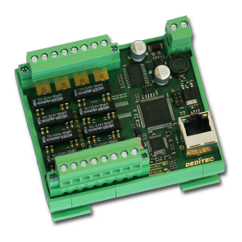
Deditec ETH-TTL-64 Guide

Hardware-Description
Juli
ETH-TTL-64
2019

INDEX
Index | 2Seite
1. Introduction 6
1.1. General remarks 6
1.2. Customer satisfaction 6
1.3. Customer response 6
2. Hardware description 8
2.1. Introduction 8
2.2. Quick installation 9
9
2.2.1. Step 1 - Installation of the software and driver
9
2.2.2. Step 2 - Connecting of the module
9
2.2.3. Step 3 - Testing the connection and the module
10
2.2.4. DIP-Switches
2.3. Technical data 12
2.4. Overview screen ETH-TTL-64 13
2.5. Power supply 14
2.6. Configuration of the voltage level of TTL-I/O's 14
2.7. Pin assignment 16
16
2.7.1. J1 - Pin assignment ETH-TTL-I/O 0-31
18
2.7.2. J2 - Pin assignment ETH-TTL-I/O 32-63
3. Software 20
3.1. Using our products 20
20
3.1.1. Access via graphical applications
20
3.1.2. Access via the DELIB driver library
20
3.1.3. Access via protocol
22
3.1.4. Access via provided test programs
3.2. DELIB driver library 23
23
3.2.1. Overview

INDEX
Index | 3Seite
24
3.2.1.1. Program under diverse operating systems
24
3.2.1.2. Program with diverse programming languages
24
3.2.1.3. Program independent of the interface
24
3.2.1.4. SDK-Kit for Programmer
25
3.2.2. Supported operating systems
25
3.2.3. Supported programming languages
27
3.2.4. Installation DELIB driver library
27
3.2.5. DELIB Configuration Utility
3.3. Integration of the DELIB 27
27
3.3.1. Integration of the delib.h in Visual-C/C++
27
3.3.2. Integration of the delib.cs in Visual-C#
27
3.3.3. Integration of the delib.cs in Visual-C# unter Windows 64bit
27
3.3.4. Integration of the delib.pas in Delphi
27
3.3.5. Integration of the delib.bas in Visual Basic
27
3.3.6. Integration of the delib.vb in VB.NET
27
3.3.7. Integration of the delib.bas in MS-Office (VBA)
27
3.3.8. Integration of the delib.dll in LabVIEW
27
3.3.8.1. Integration of the delib.dll in LabVIEW
37
3.3.8.2. Usage of the VIs in LabVIEW
4. Hardware 41
4.1. LED blinking behavior 41
4.2. DIP-Switches 44
5. DELIB API reference 48
5.1. Management functions 48
48
5.1.1. DapiOpenModule
49
5.1.2. DapiCloseModule
50
5.1.3. DapiGetDELIBVersion
51
5.1.4. DapiSpecialCMDGetModuleConfig
53
5.1.5. DapiOpenModuleEx
5.2. Error handling 54
54
5.2.1. DapiGetLastError
55
5.2.2. DapiGetLastErrorText
5.3. Reading Digital inputs 56

INDEX
Index | 4Seite
56
5.3.1. DapiDIGet1
57
5.3.2. DapiDIGet8
58
5.3.3. DapiDIGet16
59
5.3.4. DapiDIGet32
60
5.3.5. DapiDIGet64
61
5.3.6. DapiDIGetFF32
62
5.3.7. DapiDIGetCounter
63
5.3.8. DapiSpecialCounterLatchAll
64
5.3.9. DapiSpecialCounterLatchAllWithReset
65
5.3.10. Dapi_Special_DI_FF_Filter_Value_Get
66
5.3.11. Dapi_Special_DI_FF_Filter_Value_Set
5.4. Setting Digital outputs 67
67
5.4.1. DapiDOSet1_WithTimer
68
5.4.2. DapiDOSet1
69
5.4.3. DapiDOSet8
70
5.4.4. DapiDOSet16
71
5.4.5. DapiDOSet32
72
5.4.6. DapiDOSet64
73
5.4.7. DapiDOReadback32
74
5.4.8. DapiDOReadback64
5.5. Set TTL-In-/Outputs direction with DapiSpecialCommand 75
75
5.5.1. DAPI_SPECIAL_CMD_SET_DIR_DX_1
76
5.5.2. DAPI_SPECIAL_CMD_SET_DIR_DX_8
5.6. Example program 77
6. Appendix 80
6.1. Revisions 80
6.2. Copyrights and trademarks 81

I
Introduction | Seite 5
Introduction

Introduction | Seite 6
1. Introduction
1.1. General remarks
First of all, we would like to congratulate you to the purchase of a high quality
DEDITEC product.
Our products are being developed by our engineers according to quality
requirements of high standard. Already during design and development we take
care that our products have -besides quality- a long availability and an optimal
flexibility.
Modular design
The modular design of our products reduces the time and the cost of
development. Therefor we can offer you high quality products at a competitive
price.
We ensure a long delivery availability!
If semiconductors are no longer available, we can react faster. With us, usually
only modules have to be redesigned and not the entire product. This increases
the delivery availability.
1.2. Customer satisfaction
Our philosophy: a content customer will come again. Therefor customer
satisfaction is in first place for us.
If by any chance, you are not content with the performance of our product,
please contact us by phone or mail immediately.
We take care of the problem!
1.3. Customer response
Our best products are co-developments together with our customers. Therefor
we are thankful for comments and suggestions.

II
Hardware description | Seite 7
Hardware description

Hardware description | Seite 8
2. Hardware description
2.1. Introduction
ETH-Interface with 64 TTL channels
The ETH-TTL-64 provides a ethernet interface with 100/10Mbit and 64 TTL I/
Os. The high-grade case is suited for din rail mounting.
Two 37 pin d-sub sockets grants access to the I/Os. Dip switches allowing a
quick configuration of network settings.
LEDs on the board show the status of the module, the power supply, the
communication via ethernet and also the access to the I/Os.

Hardware description | Seite 9
2.2. Quick installation
2.2.1. Step 1 - Installation of the software and driver
Install the driver DELIB library with the file "delib_install.exe" from the supplied
DEDITEC-Driver CD.
These can be found in the folder "\zip\DELIB\delib_install.exe" on the
DEDITEC-Driver CD.
Note: On our website www.deditec.de you can always find the latest DELIB
driver version.
2.2.2. Step 2 - Connecting of the module
Connect the ETH-TTL-64 via ethernet cable with your network or PC.
2.2.3. Step 3 - Testing the connection and the module
In the Start menu, see "Start -> All Programs -> DEDITEC -> DELIB -> Sample
Programs" you will find some example programs to test your module.

Hardware description | Seite 10
2.2.4. DIP-Switches
DHCP and EEPROM settings can be configured via DIP-Switches. The DIP-
Switches are located on the small daughterboard with the ethernet port.
Attention: You need to reconnect the power supply to apply the settings.
DIP Switch 1
Mode / Description
ON
DHCP is active
The network settings (ip, subnet mask, DNS-Domain and
Gateway) will be received from a DHCP-Server.
OFF
DHCP is not active
The network settings (ip, subnet mask, DNS-Domain and
Gateway) will be used from thee EEPROM of the module.
Using the DELIB Configuration Utility, these settings can be
edited and saved in the EEPROM of the module.
See chapter: DELIB-Configuration-Utility

Hardware description | Seite 11
DIP Switch 2
Mode / Description
ON
EEPROM write protection is active
If the write protection is active you can not configure the
network settings using the DELIB Configuration Utility.
OFF
EEPROM write protection is not active
DIP Switch 3
Mode / Description
ON
The module starts with the parameters stored in the EEPROM.
OFF
The data stored in EEPROM values (IP address, gateway,
subnet mask, DHCP) are ignored during module startup.
The module starts with the default settings.
Default settings:
IP: 192.168.1.1
Subnet mask: 255.255.255.0
Gateway: 192.168.1.254
DHCP: Off
The values stored in the EEPROM will not be changed.
DIP Switch 4
Mode / Description
ON
Module starts normally
OFF
Only for SERVICE purposes.
Module will stay in bootloader.
The values stored in the EEPROM will not be changed.

Hardware description | Seite 12
2.3. Technical data
Power
Supply
7V to 24V DC (two pin plug-in screw terminal)
Interface
Ethernet 100/10Mbit
Input/
Outputs
64*TTL I/O (adjustable in 8- blocks as input or output)
TTL-Level
5V to 3.3V via jumper
5V to 1.5V via own power supply
Maximum
output
current
5mA for each channel
Access time
max 1kHz
API-
Bibliothek
Delib driver library for C++, C+, VB, VB.Net, Delphi and LabVIEW
Control-LED
Power - Indicates if power is supplied
Status - Displays the current operating status of the product
Activity-LED
I/O
Indicates access to the I/O channels
Interface
Activity
Displays the Ethernet communication
Connectors
2*37 pin D-sub connector
Operating
temperature
10°C..+50°C
Dimensions
90 mm x 77 mm x 42 mm (L x W x H)

Hardware description | Seite 13
2.4. Overview screen ETH-TTL-64

Hardware description | Seite 14
2.5. Power supply
The input-power-supply-range lies between +7V and +24V DC.The power
supply can be realized with a standard AC/DC adaptor with 1A output current. A
suitable plug-in connector is included in each shipment.
2.6. Configuration of the voltage level of TTL-I/O's
TTL level of 1.8 V to 5 V:
By default, you can select the TTL level of 3.3 V or 5V via jumper.
If you remove the jumper on the module, you can apply your own voltage
between 1.8 V to 5 V to the TTL-I/O module, so the possibilities of the modules

Hardware description | Seite 15
were significantly increased.
If you want to apply your own voltage, this is done via the VIN pin see chapter
Pin assignment.
The TTL-I/O's of the module can be configured in a 16 blocks.

Hardware description | Seite 16
2.7. Pin assignment
2.7.1. J1 - Pin assignment ETH-TTL-I/O 0-31
Pin
Description
Pin
Description
1
I/O 16
20
I/O 17
2
I/O 18
21
I/O 19
3
I/O 20
22
I/O 21
4
I/O 22
23
I/O 23
5
I/O 24
24
I/O 25
6
I/O 26
25
I/O 27
7
I/O 28
26
I/O 29
8
I/O 30
27
I/O 31
9
I/O 0
28
I/O 1
10
I/O 2*
29
I/O 3
11
I/O 4*
30
I/O 5
12
I/O 6
31
I/O 7
13
I/O 8
32
I/O 9
14
I/O 10
33
I/O 11
15
I/O 12
34
I/O 13
16
I/O 14
35
I/O 15
17
VIN 0-15
36
VIN 16-31
18
GND
37
GND
19
GND
Note: The VIN pin is used to apply your own voltage to the I/O's of the module.
This voltage can be between 1.8V and 5V.
If the TTL levels are set to 3.3V or 5V via jumper assignment, the VIN pin serves
as the output.
*: Until and including revision 1.2, these pins are inverted. In later revisions this

Hardware description | Seite 17
problem is solved.

Hardware description | Seite 18
2.7.2. J2 - Pin assignment ETH-TTL-I/O 32-63
Port
Pin
Port
Pin
1
I/O 48
20
I/O 49
2
I/O 50
21
I/O 51
3
I/O 52
22
I/O 53
4
I/O 54
23
I/O 55
5
I/O 56
24
I/O 57
6
I/O 58
25
I/O 59
7
I/O 60
26
I/O 61
8
I/O 62
27
I/O 63
9
I/O 32
28
I/O 33
10
I/O 34*
29
I/O 35
11
I/O 36*
30
I/O 37
12
I/O 38
31
I/O 39
13
I/O 40
32
I/O 41
14
I/O 42
33
I/O 43
15
I/O 44
34
I/O 45
16
I/O 46
35
I/O 47
17
VIN 32-47
36
VIN 48-63
18
GND
37
GND
19
GND
Note: The VIN pin is used to apply your own voltage to the I/O's of the module.
This voltage can be between 1.8V and 5V.
If the TTL levels are set to 3.3V or 5V via jumper assignment, the VIN pin serves
as the output.
*: Until and including revision 1.2, these pins are inverted. In later revisions this
problem is solved.

III
Software | Seite 19
Software

Software | Seite 20
3. Software
3.1. Using our products
3.1.1. Access via graphical applications
3.1.2. Access via the DELIB driver library
The DELIB driver library contains the DELIB API and various programs for the
configuration test of our products.
The API gives you access to all the functions you need to communicate with our
products.
In the chapter DELIB API Reference you will find all the functions of our driver
library explained and provided with application examples.
3.1.3. Access via protocol
For products with Ethernet, CAN or serial interface, we offer you our open
protocols.
These protocols can be used without our DELIB driver library on devices with
the appropriate interface. The way through our protocols are operating system
independent.
You can find our manuals Protocols & Tabs here:
Download PDF:
http://www.deditec.de/pdf/manual_d_deditec_communication_protocols.pdf
Online HTML-Manual:
http://manuals.deditec.de/de/manual_deditec_communication_protocols/index.
html
Table of contents
Other Deditec Control Unit manuals
Popular Control Unit manuals by other brands

Asus
Asus AAEON NIM-C13D Quick installation guide

KLINGER
KLINGER KHD-M4F Series Installation, operation & maintenance manual

RAK
RAK WisBlock RAK12004 quick start guide

Yoshitake
Yoshitake GD-26GS manual

Dynojet
Dynojet PCV F Installation Instructions and Technical Information

ICP DAS USA
ICP DAS USA PM-3133i quick start

Purified Air
Purified Air UV-O 500 Technical and Operations Manual

SMC Networks
SMC Networks 56-VQC1000 Series Installation and maintenance manual

acorn controls
acorn controls TEMPFLOW TZV Installation, operation and maintenance instructions

Emerson
Emerson Vanessa 30000 Series Installation and maintenance instructions

roco
roco 10727 manual

Honeywell
Honeywell V5832B Product data