JYTEK JY5312 User manual

JY5312/5315
Simultaneous Data
Acquisition Modules
User Manual
User Manual Version: V1.5.5
Revision Date: Aug 16, 2022

Table of Contents
1.Overview .............................................................................................................1
1.1 Introduction ..................................................................................................... 1
1.2 Main Features .................................................................................................. 1
1.3 Abbreviations ...................................................................................................2
1.4 Learn by example .............................................................................................2
2.Hardware Specifications ...................................................................................... 5
2.1 Analog Input Specifications ............................................................................. 5
2.2 AI Accuracy .......................................................................................................6
2.3 Temperature Coefficients ................................................................................6
2.4 AI Bandwidth ....................................................................................................7
2.5 CMRR ............................................................................................................... 8
2.6 Crosstalk ...........................................................................................................8
2.6.1 Adjacent channel .................................................................................. 8
2.6.2 Non-adjacent channel ...........................................................................9
2.7 Digital IO Specifications ................................................................................. 10
2.8 PFI Specifications ........................................................................................... 10
2.9 Power Specification ....................................................................................... 10
2.10 Physical and Environment ........................................................................... 10
2.11 Front Panel and Pin Definition .....................................................................11
3.Software ............................................................................................................13
3.1 System Requirements ....................................................................................13
3.2 System Software ............................................................................................ 13
3.3 C# Programming Language ............................................................................14
3.4 JY5312/5315 Hardware Driver .......................................................................14
3.5 Install the SeeSharpTools from JYTEK ............................................................14
3.6 Running C# Programs in Linux ....................................................................... 15
4.Operating JY5312/5315 ..................................................................................... 16
4.1 Quick Start ..................................................................................................... 16
4.2 Data Acquisition Methods ............................................................................. 16
4.2.1 Continuous Acquisition .......................................................................17
4.2.2 Finite Acquisition ................................................................................ 17
4.2.3 Single Acquisition ................................................................................18
4.2.4 Record Acquisition ..............................................................................18
Learn by Example 4.2 ...................................................................................18
4.3 Analog Input Terminal Type ...........................................................................20
4.4 Trigger Source ................................................................................................21
4.4.1 Immediate trigger ............................................................................... 21
4.4.2 Software Trigger ................................................................................. 22

4.4.3 External Analog Trigger .......................................................................23
4.4.4 External Digital Trigger ....................................................................... 28
4.5 Trigger Mode ................................................................................................. 31
4.5.1 Start Trigger ........................................................................................ 31
4.5.2 Reference Trigger ............................................................................... 31
4.5.3 ReTrigger .............................................................................................32
Learn by Example 4.5 ...................................................................................33
4.6 Digital I/O Operations ....................................................................................36
4.6.1 Static DI/DO ........................................................................................ 36
4.7 Multi-Devices Synchronization ...................................................................... 38
4.8 System Synchronization Interface(SSI)for PCIe Modules .........................40
4.9 DIP Switch in PCIe-5312/5315 ....................................................................... 40
5.Calibration .........................................................................................................42
6.About JYTEK .......................................................................................................43
6.1 JYTEK China .................................................................................................... 43
6.2 JYTEK Korea and JYTEK In Other Countries ....................................................43
6.3 JYTEK Hardware Products ..............................................................................43
6.4 JYTEK Software Platform ................................................................................44
6.5 JYTEK Warranty and Support Services ...........................................................44
7.Appendix ........................................................................................................... 44
7.1 Typical Measurement Error ........................................................................... 44
7.2 System Noise ..................................................................................................45
7.3 Temperature Drift ..........................................................................................47
8.Statement ..........................................................................................................47
Table 1 JY5312/5315 Family and Main Features ...................................................1
Table 2 JY5312/5315 on Different Bus .................................................................. 1
Table 3 TB-68 Front Panel for JY5312/5315 Series ................................................4
Table 4 Analog Input Specifications .......................................................................5
Table 5 AI Accuracy ................................................................................................6
Table 6 AI Bandwidth .............................................................................................7
Table 7 CMRR .........................................................................................................8
Table 8 Crosstalk (Adjacent channel) .................................................................... 8
Table 9 Crosstalk (Non-adjacent channel) .............................................................9
Table 10 Digital IO Specifications ........................................................................ 10
Table 11 PFI Specifications .................................................................................. 10
Table 12 Power Specification ...............................................................................10
Table 13 Physical and Environment .....................................................................10
Table 14 JY5312/5315 Pin Define ........................................................................ 12
Table 15 Notes to Legend .................................................................................... 12

Table 16 Supported Linux Versions ..................................................................... 13
Table 17 SSI Connector Pin Assignment for PCIe-5312/5315 ............................. 40
Table 18 Relationship between switch position and slot number ...................... 41
Table 19 Random Noise .......................................................................................45
Figure 1 JYPEDIA Information ................................................................................ 2
Figure 2 Experiment Setup .................................................................................... 3
Figure 3 -3dB Bandwidth ....................................................................................... 7
Figure 4 CMRR ....................................................................................................... 8
Figure 5 JY5312/5315 Front Panel .......................................................................11
Figure 6 AI Simultaneous Mode Acquisition ........................................................17
Figure 7 MultiChannel Continuous Parament ..................................................... 19
Figure 8 Multichannel Continuous Acquisition ................................................... 19
Figure 9 Differential Mode for Grounding Signal ................................................ 20
Figure 10 Differential Mode for Floating Signal .................................................. 20
Figure 11 Immediate Trigger Paraments .............................................................21
Figure 12 SoftwareTrigger Paraments .................................................................22
Figure 13 Software trigger Acquisition ................................................................ 23
Figure 14 Rising Slope Trigger ..............................................................................24
Figure 15 Falling Slope Trigger .............................................................................24
Figure 16 Hysteresis with Rising Slope Trigger ....................................................25
Figure 17 Hysteresis with Falling Slope Trigger ................................................... 25
Figure 18 Entering Window Trigger .....................................................................26
Figure 19 Leaving Window Trigger ...................................................................... 26
Figure 20 Analog Trigger Paraments ................................................................... 27
Figure 21 Waiting For Trigger .............................................................................. 27
Figure 22 Analog Trigger Acquisition ...................................................................28
Figure 23 External Digital Trigger ........................................................................ 28
Figure 24 Digital Trigger Paraments .................................................................... 29
Figure 25 Digital Trigger Acquisition ....................................................................30
Figure 26 Start Trigger ......................................................................................... 31
Figure 27 Reference Trigger ................................................................................ 32
Figure 28 Re-Trigger .............................................................................................32
Figure 29 Retrigger Paraments ............................................................................ 33
Figure 30 Retrigge rIn Start Trigger Mode ...........................................................34
Figure 31 Retrigger in Reference Trigger Mode .................................................. 34
Figure 32 Retrigger Paraments ............................................................................ 35
Figure 33 Retrigger Complete State .................................................................... 35
Figure 34 Single Digital Output ............................................................................36
Figure 35 Single Digital Input ...............................................................................37
Figure 36 Timing diagram .................................................................................... 38

Figure 37 SSI Connector in PCIe-5312/5315 ........................................................40
Figure 38 DIP Switch in PCIe-5312/5315 ............................................................. 41
Figure 39 Measurement Error ............................................................................. 45
Figure 40 Random Noise ......................................................................................45
Figure 41 Creating an Return Path ......................................................... 46
Figure 42 Gain Error due to Temperature Change ..............................................47
Figure 43 Offset Error due to Temperature Change ........................................... 47

PCIe/PXIe-5310 Series | jytek.com | 1
1. Overview
This chapter presents the information how to use this manual and quick start if you
are already familiar with Microsoft Visual Studio and C# programming language.
1.1 Introduction
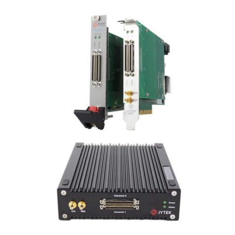
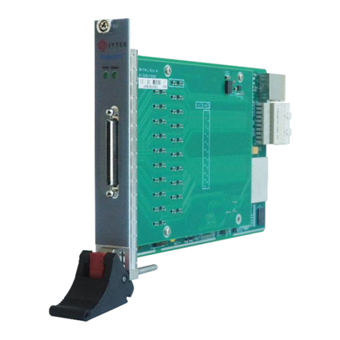
JY5312/5315 Series Simultaneous DAQ provide 16-channel, 16 bits resolution, up to
5M samples per second per channel. It also has 16 digital IO lines. JY5312/5315 can
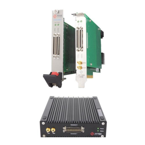
be run on PCIe, PXIe, TXI(Thunderbolt) and USB bus (coming soon) platforms.
Depending on the model number, a JY5312/5315 series provide different sampling
rate as shown in Table 1.
Table 1 JY5312/5315 Family and Main Features
Table 2 JY5312/5315 on Different Bus
1.2 Main Features
16 simultaneous anlog input channels
Maximun sample rate : 5 MS/sec per channel
16 bits resolution
4 voltage ranges: ±10 V / ±5 V / ±2 V / ±1 V
256M samples of FIFO buffer
8 ports digital IO, 2 channels per port
Analog/Digital/Software Trigger

PCIe/PXIe-5310 Series | jytek.com | 2
1.3 Abbreviations
AI: Analog Input
DI: Digital Input
DO: Digital Output
DAQ: Data AcQuisition
ADC: Analog-to-Digital Conversion
PFI: Programmable Function Interface
DIFF: Differential
1.4 Learn by example
JYTEK has added Learn by Example in this manual. We provide many sample
programs for this device. Please download and install the sample programs for this
device. You can visit our web www.jytek.com to search for the example file or you
can download a JYPEDIA excel file from our web. Open JYPEDIA and search for
JYJY5312/5315 in the driver sheet, select the latest JYJY5312/5315 Examples.zip.
This will lead you to download the sample program for this device. In addition to the
download information, JYPEDIA also has a lot of other valuable information, JYTEK
highly recommend you use this file to obtain information from JYTEK.
Figure 1 JYPEDIA Information
In a Learn by Example section, the sample program is in bold style such as Analog
Input-->Winform AI Continuous MultiChannel Soft Trigger; the property name in
the sample program is also in bold style such as SamplesToAcquire; the technical
names used in the manual is in italic style such as SampleRate. You can easily relate
the property names in the example program with the manual documentation.
In an Learn by Example 5.2~5.5 section, the experiment is set up as follow. The
JYJY5312/5315 is connected to a TB-68 terminal block. A signal source is also
connected to the same terminal block as shown Figure 2.

PCIe/PXIe-5310 Series | jytek.com | 6
2.2 AI Accuracy
Your measurement accuracy is calculated by following fomular:
For example at 5V range and 24 Hours column, if your measurement is 2V, the
accuracy of this measurement is:
You can also get a good estimate by looking up the full scale accuracy for each range.
Table 5 AI Accuracy
2.3 Temperature Coefficients
When the operating temperature is outside the last calibration temperature, the
accuracies in the table need to be adjusted. For example, In Table 4, if the operating
temperature is 3°C outside the last calibration temperature range, the temperature
adjustment at 5V range will be 3*(0.0023% of reading + 0.0153% of range) =
(0.0069% of reading + 0.0459% of range). This adjustment needs to be added to 24
Hour or 90 Days accuracy entries. In the case of the 24 Hour column, the accuracy
entry becomes (0.0092% of reading + 0.0612% of range). The same 2V measurement
now has the accuracy:

PCIe/PXIe-5310 Series | jytek.com | 13
3. Software
3.1 System Requirements
JY5312/5315 Modules can be used in a Windows or a Linux operating system.
Microsoft Windows: Windows 7 32/64 bit, Windows 10 32/64 bit.
Linux Kernel Versions: There are many Linux versions. It is not possible JYTEK can
support and test our devices under all different Linux versions. JYTEK will at the best
support the following Linux versions.
Table 16 Supported Linux Versions
3.2 System Software
When using JY5312/5315 in the Window environment, you need to install the
following software from Microsoft website:
Microsoft Visual Studio Version 2015 or above.
.NET Framework version is 4.0 or above.
.NET Framework is coming with Windows 10. For Windows 7, please check .NET
Framework version and upgrade to 4.0 or later version.
Given the resources limitation, JYTEK only tested JY5312/5315 with .NET Framework
4.0 with Microsoft Visual Studio 2015. JYTEK relies on Microsoft to maintain the
compatibility for the newer versions.

PCIe/PXIe-5310 Series | jytek.com | 14
3.3 C# Programming Language
All JYTEK default programming language is Microsoft C#. This is Microsoft
recommended programming language in Microsoft Visual Studio and is particularly
suitable for the test and measurement applications. C# is also a cross platform
programming language.
3.4 JY5312/5315 Hardware Driver
After installing the required application development environment as described
above, you need to install the JY5312/5315 hardware driver.
JYTEK hardware driver has two parts:
the shared common driver kernel software (FirmDrive)
the specific hardware driver.
Common Driver Kernel Software (FirmDrive): FirmDrive is the JYTEK’s kernel
software for all hardware products of JYTEK instruments. You need to install the
FirmDrive software before using any other JYTEK hardware products. FirmDrive only
needs to be installed once. After that, you can install the specific hardware driver.
Specific Hardware Driver: Each JYTEK hardware has a C# specific hardware driver.
This driver provides rich and easy-to-use C# interfaces for users to operate various
JY5312/5315 function. JYTEK has standardized the ways which JYTEK and other
vendor’s hardware are used by providing a consistent user interface, using the
methods, properties and enumerations in the object-oriented programming
environment. Once you get yourself familiar with how one JYTEK DAQ card works,
you should be able to know how to use all other DAQ hardware by using the same
methods.
Note that this driver does not support cross-process, and if you are using more than
one function, it is best to operate in one process.
3.5 Install the SeeSharpTools from JYTEK
To efficiently and effectively use JY5312/5315, you need to install a set of free C#
utilities, SeeSharpTools, from JYTEK. The SeeSharpTools offers rich user interface
functions you will find convenient in developing your applications. They are also

PCIe/PXIe-5310 Series | jytek.com | 15
needed to run the examples come with JY5312/5315 hardware. Please register and
down load the latest SeeSharpTools from our website, www.jytek.com.
3.6 Running C# Programs in Linux
Most C# written programs in Windows can be run by MonoDevelop development
system in a Linux environment. You would develop your C# applications in Windows
using Microsoft Visual Studio. Once it is done, run this application in the
MonoDevelop environment. This is JYTEK recommended way to run your C#
programs in a Linux environment.
If you want to use your own Linux development system other than MonoDevelop,
you can do it by using our Linux driver. However, JYTEK does not have the capability
to support the Linux applications. JYTEK completely relies upon Microsoft to
maintain the cross-platform compatibility between Windows and Linux using
MonoDevelop.
This manual suits for next models
1
Table of contents
Other JYTEK Control Unit manuals
Popular Control Unit manuals by other brands

Alfalaval
Alfalaval Pressure Relief Valve instruction manual

Pro-face
Pro-face SP-5B10 installation guide

Oriental motor
Oriental motor PKP Series operating manual

GiBiDi
GiBiDi DSC90 manual

System air
System air SYSCONTROL CWC 02 installation manual

Flow Safe
Flow Safe F84L Series Installation, operation & maintenance manual