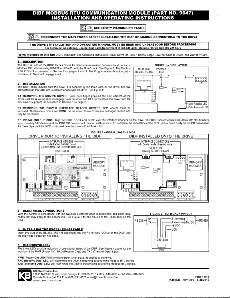
KB Electronics 9646 User manual

IODF INPUT/OUTPUT MULTI-FUNCTION EXPANSION MODULE KIT (PART NO. 9646)
INSTALLATION AND OPERATION INSTRUCTIONS
KB Electronics, Inc.
12095 NW 39th Street, Coral Springs, FL 33065-2516 ●(954) 346-4900 ●FAX (954) 346-3377
www.kbelectronics.com Page 1 of 4
(A40193) – Rev. A00 – 5/7/2013
SAFETY WARNING! Please read carefully before proceeding.
This product must be installed and serviced by a qualified technician, electrician, or electrical maintenance person familiar with its
operation and the hazards involved. Proper installation, which includes electrical connections, fusing or other current protection,
and grounding, can reduce the chance of electrical shocks, and fires, in this product or products used with this product, such as
electric motors, switches, coils, solenoids, and relays. Do not use this drive in an explosion-proof application. Eye protection must
be worn and insulated adjustment tools must be used when working with drive under power. This product is constructed of
materials (plastics, metals, carbon, silicon, etc.) which may be a potential hazard. Proper shielding, grounding, and filtering of this
product can reduce the emission of radio frequency interference (RFI) which may adversely affect sensitive electronic equipment.
It is the responsibility of the equipment manufacturer and individual installer to supply this Safety Warning to the ultimate end user
of this product. (SW 8/2012)
The drive contains electronic Start/Stop circuits, which can be used to start and stop the drive. However, these circuits are never
to be used as safety disconnects since they are not fail-safe. Use only the AC Line for this purpose.
Be sure to read and follow all instructions carefully. Fire and/or electrocution can result due to improper use of this product.
Items Included in this Kit:IODF Input/Output Multi-Function Expansion Module, Installation and Operating Instructions, Cover for Case
A Drives, Cover for Case B Drives, Trimpot Adjustment Tool, and Warranty Card.
– THE DRIVE'S INSTALLATION AND OPERATION MANUAL MUST BE READ AND UNDERSTOOD BEFORE PROCEEDING –
– FOR ASSISTANCE, CONTACT OUR SALES DEPARTMENT –
WARNING! HIGH VOLTAGE! DISCONNECT AC LINE BEFORE INSTALLING THE IODF.
1 DESCRIPTION
The IODF is used on the KBDF Series Drives to provide
additional input/output lines and increase the functionality
of the standard inputs/outputs of the drive. An additional
Multi-Function Relay is also provided. See Figure 1.
2 INSTALLATION
The IODF easily mounts onto the drive. It is secured by
the three clips on the drive. The two connectors on the
IODF are used to interface with the drive. See Figure 2.
FIGURE 2 – INSTALLING THE IODF
MEMORY
MODULE
MEMORY
MODULE
DRIVE PRIOR TO INSTALLING THE IODF IODF INSTALLED ONTO THE DRIVE
FIGURE 1 – IODF LAYOUT

IODF INPUT/OUTPUT MULTI-FUNCTION EXPANSION MODULE KIT (PART NO. 9646)
INSTALLATION AND OPERATION INSTRUCTIONS
KB Electronics, Inc.
12095 NW 39th Street, Coral Springs, FL 33065-2516 ●(954) 346-4900 ●FAX (954) 346-3377
www.kbelectronics.com Page 2 of 4
(A40193) – Rev. A00 – 5/7/2013
2.1 REMOVING THE DRIVE'S COVER:
Press on the both finger grips on both side corners of the cover until the retaining clips disengage from the drive and lift it up. This cover must
be replaced with the new cover (supplied), as described in Section 5, on page 4.
2.2 REMOVING THE DRIVE'S INTERFACE HEADER COVERS:
Both covers must be removed off of headers CON1 and CON2, on the drive. These covers are no longer needed and may be discarded.
2.3 INSTALLING THE IODF
Align the IODF CON1 and CON2 over the corresponding headers on the drive. The IODF should easily drop down into the headers
approximately 1/8" (3 mm) and the IODF PC board should rest on all three clips. To complete the installation of the IODF, press down firmly
on the PC board near the top two clips and then on the shorter Terminal Block TB2 until the IODF is secured onto the drive with all three clips.
3 ELECTRICAL CONNECTIONS
Wire the control in accordance with the National Electrical
Code requirements and other local codes that may apply
to the application. See Figure 3, for connections to
Terminal Blocks TB1 and TB3. See Table 1 for the
terminal block wire and tightening torque specifications.
WARNING! HIGH VOLTAGE! Read Safety
Warnings, on page 1, before using the drive.
Disconnect the main power before making
connections to the drive or the IODF. To avoid electric
shock, be sure to properly ground the drive.
Application Note: To avoid erratic operation, do not
bundle AC Line input and motor wires with each other.
Also, do not bundle motor wires from multiple drives in the
same conduit. Use shielded cables on all signal wiring
over 12" (30 cm). The shield should be earth grounded on
the drive side only.
TABLE 1 – TERMINAL BLOCK WIRE AND TIGHTENING TORQUE SPECIFICATIONS
Maximum
Wire Size (Cu)
Recommended
Tightening Torque
Description Location
AWG mm2lbs-in kg-cm
MFITs and Signals In/Out TB1 16 1.31 1.7 1.9
Multi-Function Output Relay TB3 16 1.31 2.6 2.9
3.1 MULTI-FUNCTION INPUT TERMINALS
MFIT 6 is factory programmed for Up Frequency Command (Function 7.05 set to "0003"). MFIT 7 is factory programmed for Down Frequency
Command (Function 7.06 set to "0004"). When the MFIT 6 contact is closed, the drive's frequency will increase. When the MFIT 7 contact is
closed the drive's frequency will decrease. Also see Section 8.4.2.3, on page 34 of the manual. MFIT 6 and MFIT 7 can be changed from their
factory settings of Up Frequency Command and Down Frequency Command by reprogramming Functions 7.06 and 7.07, as shown in Table
2, on page 3. Also see Tables 3 and 4, on page 3.
Free-Running Operation: When the Up Contact is closed, the drive output frequency will increase for the duration of the contact closure.
When the Up Contact is opened, the drive output frequency will stop increasing. When the Down Contact is closed, the drive output frequency
will decrease for the duration of the contact closure. When the Down Contact is opened, the drive output frequency will stop decreasing.
FIGURE 3 – CONNECTION DIAGRAM

IODF INPUT/OUTPUT MULTI-FUNCTION EXPANSION MODULE KIT (PART NO. 9646)
INSTALLATION AND OPERATION INSTRUCTIONS
KB Electronics, Inc.
12095 NW 39th Street, Coral Springs, FL 33065-2516 ●(954) 346-4900 ●FAX (954) 346-3377
www.kbelectronics.com Page 3 of 4
(A40193) – Rev. A00 – 5/7/2013
Incremental Operation: For each activation of the Up Contact, the drive output frequency will increase incrementally, equal to the frequency
set by Function 7.15 (factory set to 1.00 Hz). For each activation of the Down Contact, the drive output frequency will decrease incrementally,
equal to the frequency set by Function 7.15 (factory set to 1.00 Hz).
Note: In Incremental Operation, if the Up or Down Contact is maintained for longer than 2 seconds, the drive output frequency will "free run"
up or down in increments set by Function 7.15, for the duration of the contact closure. The rate of change is equal to the Accel/Decel settings
in Function Nos. 3.03 and 3.04. When the contact is opened, the drive output frequency will stop changing.
TABLE 2 – IODF INPUT AND OUTPUT CONNECTIONS
Terminal Block No. Description Specifications
13 Open Collector
Output NPN
14 MFIT 6
15 MFIT 7
N.O. Contacts or NPN / PNP Transistors, 7 Preset Frequencies, Up Frequency Command,
Down Frequency Command, Accel/Decel #2, Forward / Stop Command, Reverse / Stop Command,
External Fault (N.O. Contact), Reset, N.O. Start (2-Wire or 3-Wire Start/Stop),
N.C. Stop (3-Wire Start/Stop), External Fault (N.C. Contact)
16 Common1──
17 Power Supply +5 Volts DC at 1 mA Max.
18 Analog Input #2 0-2.5 thru 0-25 Volts DC
(TB1 on IODF)
161413 15 17 1918
19 Common1──
N.O. Normally Open
COM Relay Common2
(TB3 on IODF)
N.C. Normally Closed
Run, Fault, Target Frequency (5.03 ± 5.04), Frequency Threshold Level (> 5.03 – 5.04),
Frequency Threshold Level (< 5.03 + 5.04), I2t or I•t Fault, Load Loss (See 5.05), External Fault
Notes: 1. Common Terminals 16 and 19 are internally wired together. These terminals are also internally wired to Terminals 4 and 11 on the
drive. 2. Relay Common is not internally wired to Common Terminals 14 and 16 (or Common Terminals 4 and 11 on the drive).
TABLE 3 – IODF MULTI-FUNCTION INPUT TERMINAL, FUNCTION, AND FACTORY CODE ASSIGNMENT
Multi-Function Input Terminal* 6 7
Number On Terminal Block 14 15
Function 7.05 7.06
Factory Code Setting 0003 0004
Code Description Up Frequency Command Down Frequency Command
*Each Multi-Function Input Terminal is controlled by a specific Function. Although factory set to a specific code, they can also be
reprogrammed to any code "0000" – "0012" listed in Table 2, above. Also see Function Group 7, on page 60, in the manual.
3.2 MULTI-FUNCTION OUTPUT RELAY
The connections for the Multi-Function Output Relay are located on Terminal Block TB3. The Multi-Function Output Relay is factory
programmed to function as a "Run" Relay (Function 5.01 set to "0000"). When the drive is put into the Run Mode, the relay contacts will
change state (the Normally Open (N.O.) contact will close and the Normally Closed (N.C.) contact will open). See Table 4.
TABLE 4 – IODF MULTI-FUNCTION OUTPUT RELAY "RUN" AND "FAULT" OPERATING MODES
"Run" Relay Mode
(Function 5.00 Set to "0000")
"Fault" Relay Mode
(Function 5.00 Set to "0001")
Drive Operating
Condition N.O. Contact N.C. Contact N.O. Contact N.C. Contact
Power Off Open Closed Open Closed
Power On (Stop Mode) Open Closed Closed Open
Run Mode Closed Open closed Open
All Faults Open Closed Open Closed

IODF INPUT/OUTPUT MULTI-FUNCTION EXPANSION MODULE KIT (PART NO. 9646)
INSTALLATION AND OPERATION INSTRUCTIONS
KB Electronics, Inc.
12095 NW 39th Street, Coral Springs, FL 33065-2516 ●(954) 346-4900 ●FAX (954) 346-3377
www.kbelectronics.com Page 4 of 4
(A40193) – Rev. A00 – 5/7/2013
Other Programmable Functions of the Multi-Function Output Relay (Function 5.01)
Code Description
0000: Run
0001: Fault
0002: Target Frequency (Function 5.03 ± Function 5.04)
0003: Frequency Threshold Level (>Function 5.03 – Function 5.04)
0004: Frequency Threshold Level (<Function 5.03 + Function 5.04)
0005: I2t or I•t Fault
0006: Load Loss (See Function 5.05)
0007: External Fault
3.3 ANALOG INPUT
Connect the 0-2.5 thru 0-25 Volt DC signal input to Terminal "18" and the common to Terminal "19". Connect the Start (Jumper) to Terminal
"9" (on the drive's TB1), which is factory set for N.O. Start ("0010"), and to either common Terminal "4" or "11"(on the drive's TB1).
3.4 SCALE TRIMPOT
If the input Signal is higher than 5 Volts DC, use the SCALE Trimpot to attenuate it. Apply the maximum signal input and set the drive for full
speed output and observe the display. Rotate the SCALE Trimpot counter clockwise until the drive output frequency begins to drop. Then,
rotate the SCALE Trimpot clockwise until the display returns to the maximum output frequency.
Set the signal Slope and Type and adjust the Gain, Offset, and Response Time as desired. See Section 8.4.2.1, on page 30 of the manual.
4 DIAGNOSTIC LEDs
The two LEDs provide indication of operational status of the IODF. See Figure 1, on page 1, for the location of the PWR (Power On) and ST
(Status) LEDs.
PWR (Power On) LED: When power is applied to the drive, the PWR LED will illuminate green.
ST (Status) LED: During normal operation, the ST LED is not illuminated. If the IODF experiences a communication error, the ST LED will
flash red. If the ST LED flashes, disconnect power to the drive and recheck that the IODF is properly installed. If, after checking the installation
of the IODF, the ST LED flashes again, contact our Sales Department.
5 INSTALLING THE NEW COVER
After installing and wiring the IODF, it is necessary to install the new cover (supplied). For Case A drives, use the small cover and for Case B
drives, use the large cover. Insert the cover's tab into the slot on the drive and then gently press down on the cover until it snaps into place
and is secured onto the drive.
END OF INSTALLATION INSTRUCTIONS
Table of contents
Other KB Electronics Control Unit manuals
Popular Control Unit manuals by other brands

Riello
Riello CSD 35 Instruction booklet

Glas-Col
Glas-Col PLSM Series Operating and safety instructions

Lütze
Lütze DIOLINE PLC operating instructions

Siemens
Siemens SIRIUS ACT 3SU1400-2EM10-6AA0 Original operating instructions

Comelit
Comelit Simplebus1 Ultra UT1020 Technical manual

Lütze
Lütze LION microPLC operating instructions