Intermaxillary Fixation System IMF | 9
www.medartis.com
Surgical Technique
IMF Screws Application
Information on the application of the MODUS 2 IMF screws.
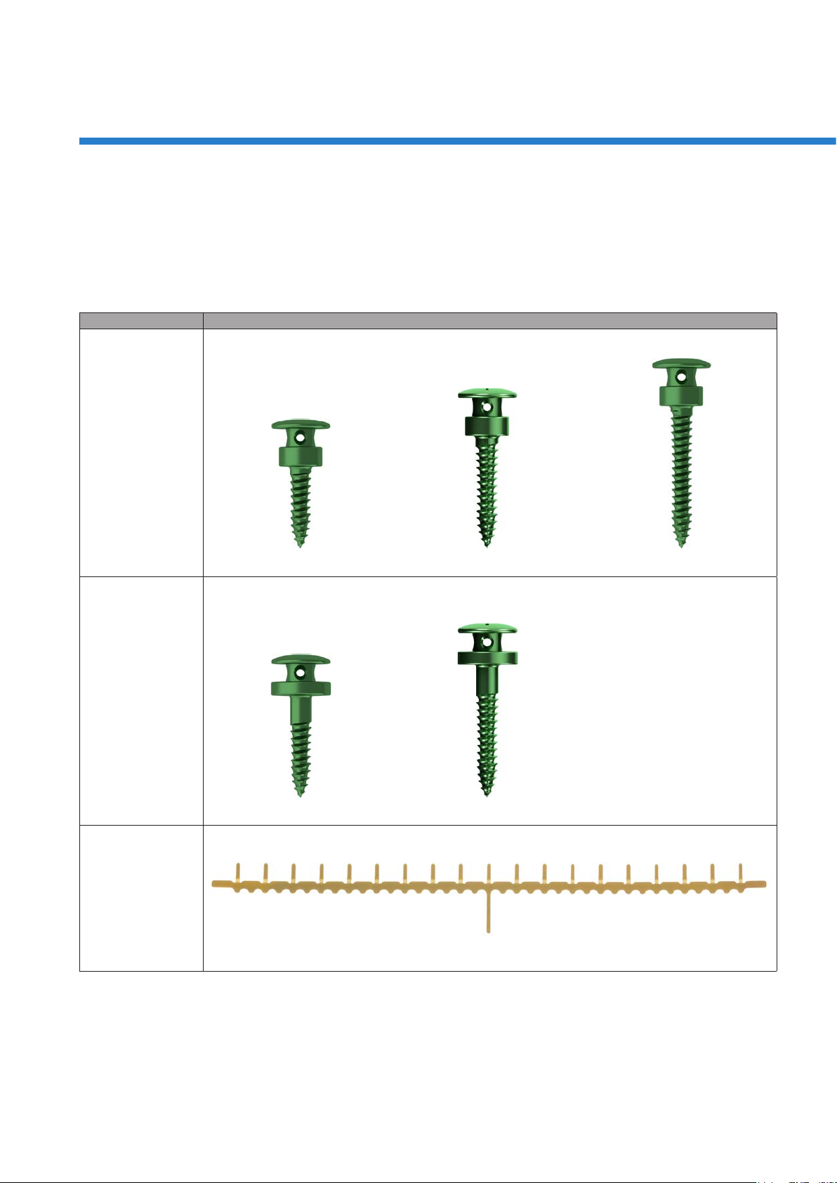
M2-5248.08 2.0 IMF SpeedTip screw, without plateau, 8 mm
M2-5248.11 2.0 IMF SpeedTip screw, without plateau, 11 mm
M2-5248.14 2.0 IMF SpeedTip screw, without plateau, 14 mm
M2-5249.08 2.0 IMF SpeedTip screw, with plateau, 8 mm
M2-5249.11 2.0 IMF SpeedTip screw, with plateau, 11 mm
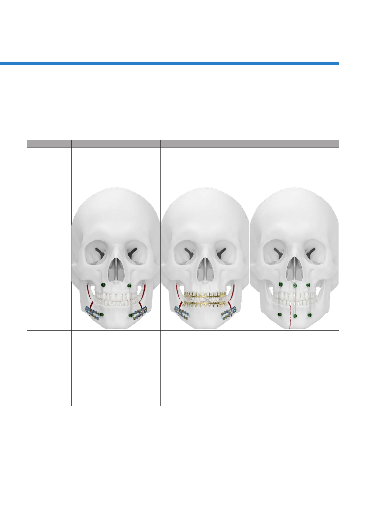
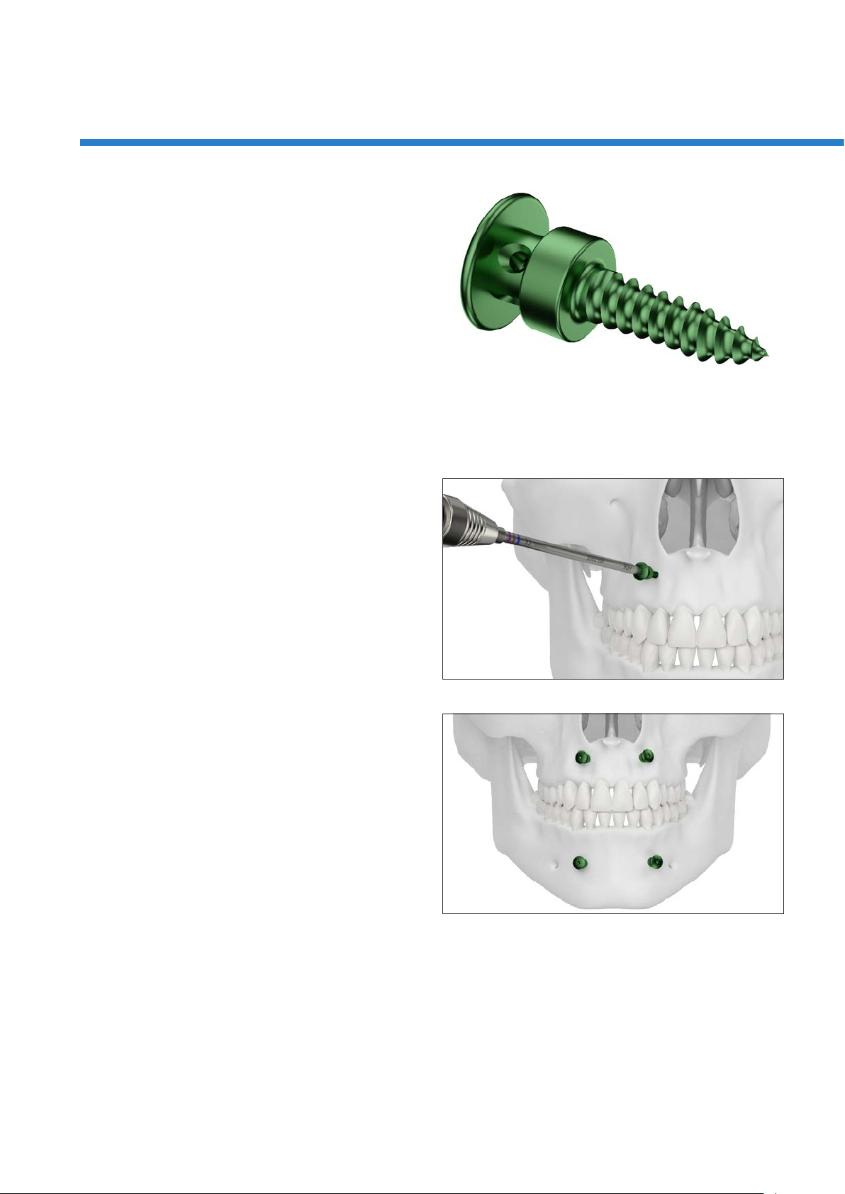
Determining the Screw Position
Screw placement sites are selected considering anatomical
structures (i. e. root apices, neurovascular bundles or nasal
mucosa) and fracture positions.
In the maxilla, the screws are placed above or between the
root apices.
In the mandible, the screws are placed below or between the
root apices.
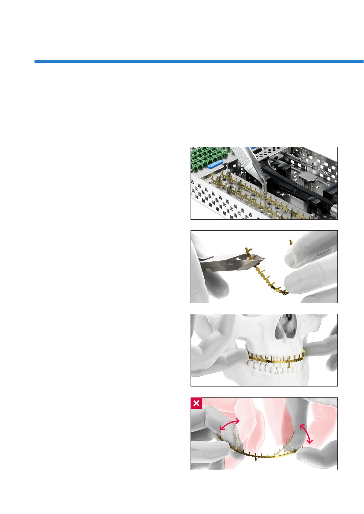
Caution
When inserting the screws, attention must be paid to the
course of the inferior alveolar nerve.
Notice
For an intermaxillary xation, a minimum of two screws in
the maxilla and two screws in the mandible is recommended.
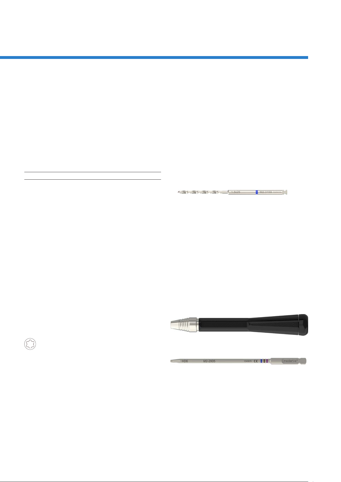
Caution
Do not insert MODUS 2 IMF into root apices. This can lead
to an injury of the root apices and /or breakage of the screw.