3
Content
1 Introduction 7
1.1 Intended use 7
1.2 About this handbook 7
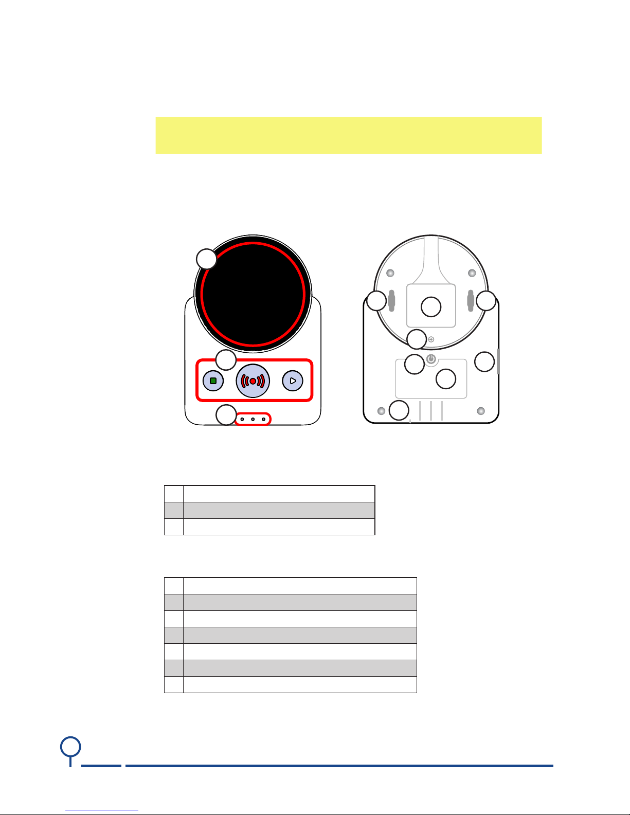
2 The main unit 8
2.1 Overview 8
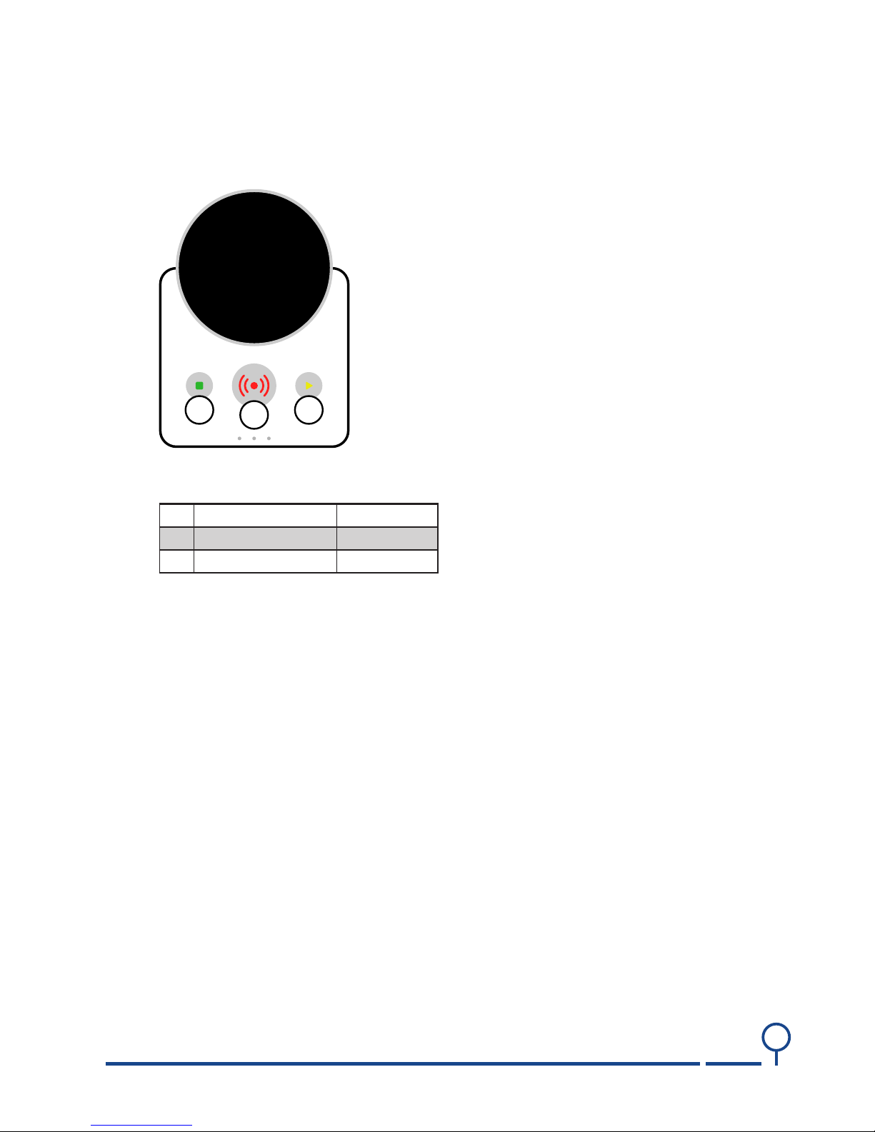
2.2 Buttons 9
2.2.1 Alarm button (B1) 9
2.2.2 Reset button (B2) 9
2.2.3 Extra button (B3) 9
2.3 LEDs 10
2.4 ConneNOVO PSTN/GSMtors on NOVO IP/GSM and 11 11
2.4.1 IP connector (C1) 11
2.4.2 AC connector (C2) 11
2.5 External GSM antenna (EA) 11
2.6 Connectors on NOVO PSTN/GSM and PSTN 12
2.6.1 TELE connector (C1) 12
2.6.2 LINE connectorLINE (C2) 12
2.6.3 AC connector (C3) 12
2.6.4 External GSM antenna (EA) 12
2.6.5 External antenna 13
2.7 On/O button (PS1) 14
2.8 Accumulator lid 15
2.8.1 Replacing the accumulator 16
2.9 Mounting the SIM card 16
2.10 Mounting the NOVO 17
2.10.1 Key holes 17
3 Indications 18
3.1 Visual indications 18
3.1.1 Front LEDs 18
3.1.2 Alarm button (L4) LED indications 19
3.1.3 Reset button LED (L5) indications 19
3.1.4 Extra button LED (L6) indications 19
3.1.5 Control mode LED indications 20
3.1.6 Service mode LED indications 20
3.1.7 Unit boot/startup 20
3.2 Acoustic indications 20
3.2.1 Aer activating an alarm 20
3.2.2 Disconnection signal 20
3.2.3 Warning functions in Idle mode 20