medical bees F-31 Series User manual

0483
Data
05 February 2021
IFU GA-001-02
Revision
03
Page
1 of 88
User’s Manual
F-31-XXX-XX
F-40-XXX-XX
Battery-powered tools for
large bone surgery
Orthopaedic Cordless Drill / Saw System
medical bees GmbH
Friedrich-Woehler-Strasse 13
78576 Emmingen-Liptingen
Germany
0483
Data
05 February 2021
IFU GA-001-02
Revision
03
Page
2 of 88
Table of Contents
Table of Contents .................................................................................................................................. 2
1Introduction and product description ........................................................................................... 6
1.1 General information ..................................................................................................................... 6
1.2 Intended use and indications...................................................................................................... 6
1.2.1 Handpieces, Battery (Power Pack) and attachments.................................................................. 6
1.2.2 Cleaning and maintenance accessories...................................................................................... 6
1.3 Contraindications......................................................................................................................... 6
1.3.1 Handpieces, Battery (Power Pack) and attachments.................................................................. 6
1.3.2 Cleaning and maintenance accessories...................................................................................... 6
1.4 Application.................................................................................................................................... 7
1.4.1 Application duration..................................................................................................................... 7
1.4.2 Patient population........................................................................................................................ 7
1.4.3 The user and the field of application ........................................................................................... 7
1.4.4 Service life................................................................................................................................... 7
1.5 Safety and warning instructions................................................................................................. 7
1.5.1 General safety instructions ................................................................................................. 7
1.5.2 Cleaning and care of the bee-system................................................................................ 7
1.5.3 Combination products and tools ........................................................................................ 8
1.5.4 The User / Application ....................................................................................................... 8
1.5.5 Users and/or patients......................................................................................................... 8
1.5.6 Operation and battery mode.............................................................................................. 8
1.6 Combination products and accessories.................................................................................... 9
1.6.1 Accessories to be used / Scope of delivery ................................................................................ 9
1.6.2 Combinability of individual beesystem components.................................................................. 10
1.6.3 Recommended cutting tool........................................................................................................ 13
1.6.4 Storage and Transport.................................................................................................. 14
1.6.5 Disposal.......................................................................................................................... 14
1.6.6 Guarantee.................................................................................................................................. 14
2Operation of the device................................................................................................................. 15
2.1 Description of the controls, indication functions and symbols ............................................ 15
2.1.1 Drilling / reaming machine (F-31-100-00).................................................................................. 15

0483
Data
05 February 2021
IFU GA-001-02
Revision
03
Page
3 of 88
2.1.2 Drilling machine (F-31-150-00).................................................................................................. 16
2.1.3 Oscillating saws Synthes AO connection (F-31-300-00; F-31-301-00)..................................... 17
2.1.4 Oscillating saw Stryker Sawblade connection (F-31-310-00/F-31-311-00) .............................. 18
2.1.5 Straight Oscillating saw Stryker Sawblade connection (F-40-100-00/F-40-101-00)................. 19
2.1.6 Straight Oscillating saw Synthes AO connection (F-40-110-00/F-40-111-00).......................... 20
2.1.7 Sternum saw/ reciprocating saw with keyless chuck (F-31-601-00)......................................... 21
2.1.8 Oscillating reaming machine (F-31-700-00).............................................................................. 22
2.1.9 Power Pack (F-30-900-00)........................................................................................................ 23
2.1.10 Charging unit (e.g. F-30-900-50)............................................................................................. 23
2.2 Start up........................................................................................................................................ 24
2.2.1 Power pack insertion................................................................................................................. 24
2.2.2 Power pack removal.................................................................................................................. 25
2.3 Battery capacity.......................................................................................................................... 27
2.3.1 Available battery capacity.......................................................................................................... 27
2.3.2 Power pack overheating............................................................................................................ 27
2.3.3 Energy saving function.............................................................................................................. 27
2.4 Power pack, charging, transport and storage ............................................................... 28
2.5 LED light indications.................................................................................................................. 28
2.5.1 Light indications during handpiece operation............................................................................ 28
2.5.2 The meaning of light indications................................................................................................ 29
2.6 Charging units ............................................................................................................................ 30
2.6.1 Charger start up......................................................................................................................... 30
2.6.2 Charger cleaning ....................................................................................................................... 30
2.6.3 Power pack charging................................................................................................................. 31
2.6.4 Charge new or longer unused power packs.............................................................................. 31
2.6.5 Power pack storage................................................................................................................... 31
2.6.6 Charge control indicators on the charger and on the power pack ............................................ 32
2.6.7 Indications on the power pack after removal from the charger ................................................. 32
2.6.8 Charger disconnection from the mains...................................................................................... 33
2.7 Application of drilling / reaming machines (F-31-100-00 and F-31-150-00).......................... 33
2.7.1 Start up...................................................................................................................................... 33
2.7.2 The oscillating mode on and off ................................................................................................ 33
2.7.3 Mode switching between drilling and reaming (only with F-31-100-00).................................... 33
2.7.4 Assembly / disassembly of the attachments/chucks for drilling / reaming machines (F-31-100-
00 and F-31-150-00).............................................................................................................................. 34
2.7.5 Attachment mounting................................................................................................................. 35
2.7.6 Mount cutting tools into the attachments / chucks and remove again ...................................... 35
2.7.7 Attachment removal................................................................................................................... 36
2.7.8 Rotating attachments / chucks .................................................................................................. 36

0483
Data
05 February 2021
IFU GA-001-02
Revision
03
Page
4 of 88
2.8 Application of oscillating saws Synthes AO saw blade connection (F-31-300-00; F-31-301-
00) 43
2.8.1 Start up of oscillating saws........................................................................................................ 43
2.8.2 Saw head positioning ................................................................................................................ 43
2.8.3 Replacement of saw blades ...................................................................................................... 43
2.8.4 Application of oscillating saws................................................................................................... 45
2.8.5 Recommendations for handling of saw blades ......................................................................... 45
2.9 Application oscillating saw Stryker saw blade connection (F-31-310-00, F-31-311-00)...... 45
2.9.1 Start-up of oscillating saw ......................................................................................................... 46
2.9.2 Saw head positioning ................................................................................................................ 46
2.9.3 Replacement of saw blades ...................................................................................................... 46
2.9.4 Application of oscillating saws................................................................................................... 48
2.9.5 Recommendations for handling of saw blades ......................................................................... 48
2.10 Application of reciprocating saw (F-31-601-00) .................................................................... 48
2.10.1 Start up of reciprocating saw................................................................................................... 49
2.10.2 Replacement of saw blades .................................................................................................... 49
2.10.3 Works with saw blades............................................................................................................ 50
2.10.4 Recommendations for handling of saw blades ....................................................................... 50
2.11 Application of sternum saws (F-31-601-00)........................................................................... 51
2.11.1 Start-up of sternum saw .......................................................................................................... 51
2.11.2 Replacement of saw blades .................................................................................................... 51
2.11.3 Works with sternum saws........................................................................................................ 51
2.11.4 Recommendations for handling of saw blades ....................................................................... 52
2.11.5 Keyless version (F-31-601-00)................................................................................................ 52
2.12 Application of oscillating reaming machine (F-31-700-00).................................................. 54
2.12.1 Start up.................................................................................................................................... 54
2.12.2 Mounting/dismounting of a tool ............................................................................................... 54
2.12.3 Cutting tool mounting............................................................................................................... 55
2.12.4 Cutting tool dismounting.......................................................................................................... 56
3Care and maintenance (after validated cleaning and sterilisation procedures)..................... 57
3.1 General information ................................................................................................................... 57
3.1.1 Extraordinary transmissible pathogens ..................................................................................... 57
3.2 Preparation to cleaning.............................................................................................................. 58
3.2.1 Dismantling................................................................................................................................ 58
3.3 Manual cleaning.......................................................................................................................... 59
3.3.1 Machine / handpiece ................................................................................................................. 59
3.3.2 Attachments............................................................................................................................... 60
3.4 Mechanical cleaning after manual pre-cleaning ..................................................................... 61
3.4.1 Manual pre-cleaning of the machine/handpiece ....................................................................... 61

0483
Data
05 February 2021
IFU GA-001-02
Revision
03
Page
5 of 88
3.4.2 Manual pre-cleaning of the attachments / chucks..................................................................... 62
3.4.3 Mechanical cleaning.................................................................................................................. 63
3.5 Oiling / maintenance .................................................................................................................. 65
3.6 Packaging.................................................................................................................................... 65
3.7 Sterilisation................................................................................................................................. 65
3.8 Repairs and Technical Service ................................................................................................. 66
4Troubleshooting ............................................................................................................................ 67
4.1 Device/handpiece and lid........................................................................................................... 67
4.2 Power pack.................................................................................................................................. 69
4.3 Attachments/chucks and tools ................................................................................................. 71
4.4 Charging unit .............................................................................................................................. 72
5Technical data................................................................................................................................ 73
5.1 Operating cycle........................................................................................................................... 73
5.2 Device specification................................................................................................................... 74
5.3 Environmental conditions ......................................................................................................... 78
5.4 Applicable standards ................................................................................................................. 78
5.5 Electromagnetic compliance..................................................................................................... 79
6Order information............................................................................................................ 83
6.1 Handpieces ................................................................................................................................. 83
6.2 Power Pack (battery, motor, electric)....................................................................................... 83
6.3 Attachments................................................................................................................................ 84
6.4 Cleaning and care of the bee-system....................................................................................... 84
7Used symbols ................................................................................................................................ 85
8Address / Report............................................................................................................................ 88

0483
Data
05 February 2021
IFU GA-001-02
Revision
03
Page
6 of 88
1 Introduction and product description
1.1 General information
Before any product use, read carefully this User’s Manual, while keeping it easily available
for the Operator or for appropriate service personnel.
Read carefully all the symbol-marked caution and warning texts. Incorrect use of
the products may lead to serious injuries of the patient, the user or other persons.
This is a User’s Manual for individual machines, including accessories. These machines can be used
either as one system or as separate units.
1.2 Intended use and indications
1.2.1 Handpieces, Battery (Power Pack) and attachments
The basic features of the beesystem serve the purpose of the medullary cavity expansion (medullary
canal; Cavitas medullaris) in preparation for implant setting by drilling, reaming, bolting, sawing and
severing of bones (or bone material). The system may be used both for resection of distal femur and
tibial condyles and for iliac bone preparation.
The system consists of battery-operated drive units with a range of attachments and accessories for
drilling, reaming and bolting operations, for mounting of pins and wires, as well as for cutting of bones
or hard tissues in general traumatic and endoprosthetic surgery.
Sternum saws, being part of the system, are intended for thorax surgery procedures and used for
sternum separation.
1.2.2 Cleaning and maintenance accessories
The cleaning and maintenance accessories are used for cleaning and processing of the beesystem
during transport and storage, culminating during surgical applications. The maintenance kit is also
used for storage and repairs of appropriate components.
A sterile funnel is a special component, intended to protect any direct contact between the non-sterile
power pack and the sterile handpiece body, after the latter is set up and sterilised for surgical use.
1.3 Contraindications
1.3.1 Handpieces, Battery (Power Pack) and attachments
No contraindication has been identified, which would speak against the use of the drive units and the
accessories.
With regards to cutting, drilling and reaming tools to be used in patients with the Creutzfeldt-Jakob
disease (CJD), who - because of associated infection hazards - are regarded to be risk patients - the
procedures shall always be undertaken with the use of disposable instruments.
Any applications of the system, other than those, specified above, are neither intended by design nor
tested and shall thus be forbidden.
1.3.2 Cleaning and maintenance accessories
The cleaning kit shall exclusively be used for the purpose for which it has been intended in the medical
fields and operated by educated and qualified personnel. The attending physician or an appropriate
medical staff member shall be responsible for cleaning kit selection with accessories for defined
applications, as well as for adequate training and correct management.

0483
Data
05 February 2021
IFU GA-001-02
Revision
03
Page
7 of 88
1.4 Application
1.4.1 Application duration
The products are intended for short application periods (< 60 min.)
1.4.2 Patient population
Apart from the contraindicated applications, specified both before and in this User’s Manual. there are
no limitations with regards to patient population.
1.4.3 The user and the field of application
The bee-system (including the cleaning and maintenance accessories) shall be used exclusively by
properly educated and qualified personnel. The products are intended exclusively for the medical field
and shall, therefore, be used at suitable theatre environment. It is an essential requirement that the
user, as well as the appropriate medical staff, get familiar with the instruments before their practical
handling.
1.4.4 Service life
The medical bees GmbH Company provides one-year inspection and maintenance by authorised
service stations (e.g., the Medical bees GmbH). The medical bees GmbH shall assume no
responsibility for any defects / failures, arising either from improper handling of the devices or from
their unauthorised maintenance. Assuming proper handling and authorised maintenance of the device,
its service life shall be, at least, 3 years (except wear & tear parts).
Since the products are subject to normal wear, they shall regularly be inspected or maintained,
Appropriate recommendations are specified in particular parts of the User’s Manual.
The date of manufacturing can be retrieved from the Manfacturing date number.
1.5 Safety and warning instructions
General safety and warning instructions are listed below. They will individually be added and specified
in particular parts of the present User’s Manual.
1.5.1 General safety instructions
•It is recommended to have a spare system ready at all times for immediate use, since
technical problems can never be entirely excluded. The same recommendation applies to
lengthy and long lasting procedures.
•Components with visible defects (for example, after being dropped) shall not be used.
•The system shall not be used in the presence of oxygen, nitrous oxide or of flammable
mixtures of volatile anaesthetic gases and the air.
•With regard to electromagnetic compatibility (EMV), it is imperative to learn the contents of the
appropriate chapter of this User’s Manual.
1.5.2 Cleaning and care of the bee-system
•Both before the first and all subsequent applications, the driving units, the attachments and
the accessories shall undergo a complete reprocessing procedure.
•Protective covers and films shall fully be removed before sterilisation.
•In order to assure proper performance of the system, the medical bees Company
recommends its cleaning and care after every use to be performed according to the
instructions provided in the chapter “Care and Maintenance” of this User’s Manual.

0483
Data
05 February 2021
IFU GA-001-02
Revision
03
Page
8 of 88
•Moving parts shall be maintained for their smooth operation with a special lubrication oil;
recommended by the bee-system GmbH is a spray oil agent (F-30-900-60) or a paraffin oil,
suitable for sterilisation.
•In order to guarantee proper performance of the system, the medical bees GmbH Company
recommends an annual maintenance and inspection to be carried out by one of their medical
customer service stations.
•The Power Pack shall by no means be processed (by manual or automatic cleaning) or
sterilised
•It is imperative that the sterile funnel is sterilised after each use in order to guarantee the
system sterility, when a non-sterile Power Pack is inserted into a sterile handpiece.
1.5.3 Combination products and tools
•New cutting tools shall be used for each surgical procedure.
•For protection against heat necrosis of tissues, cutting tools shall always be flushed with
a coolant.
•In order to guarantee proper performance of the system, only original cutting tools shall be
used, obtained either from the medical bees GmbH or from another vendor, recommended by
the medical bees GmbH (the same shall apply to the battery-loading equipment)
1.5.4 The User / Application
•The User shall be responsible for proper intraoperative handling and use of the products.
•If the system is used in connection with some implant system, then its use shall be
subordinate to the surgical technique of the procedure
•The Manufacturer shall assume no responsibility for damages, which may arise from improper
operation of the system or from its maintenance provided by unauthorised service stations
•The machines get heated under continuous load. In order to avoid exceeding of permissible
surface temperature of the device, appropriate cooling phases shall be implemented. A
description of the issue is provided in the Instructions for Use.
1.5.5 Users and/or patients
•Note to the user and/or patient: All serious incidents relating to the device must be notified to
the manufacturer and the competent authority of the Member State in which the user and/or
patient is established.
1.5.6 Operation and battery mode
•In order to avoid injuries, the locking mechanism of the device shall be activated before the
device is put aside, i.e., the selection switch shall be set at the LOCK position (the symbol of
locked padlock). In addition, the bee-system device shall be handled in its lateral position in
order to avoid possible tipping and falling down.
•The device shall be put in operation only with its fully charged power pack. It must be ensured
that the power pack has been charged in good time. It is recommended that the power pack is
returned to the charging unit immediately after a given procedure is completed.
In order to guarantee sterility, the power pack can be replaced during surgical procedure only
according to the instructions provided in the User’s Manual.
0483
Data
05 February 2021
IFU GA-001-02
Revision
03
Page
9 of 88
1.6 Combination products and accessories
1.6.1 Accessories to be used / Scope of delivery
The system comprises multiple handpieces (drilling machine, reaming machine, sagittal saw, sternum
saw, 2° and 4° oscillating saw, oscillating reaming machine). One or more power packs (battery, motor
and electronic), as well as various attachments which belong to the system.
The power packs shall be charged with an appropriate charger of the medical bees (F-30-900-50 /
F30-900-51 / F-30-900-52)
In order to ensure trouble-free performance of the system, the manufacturers of cutting tools,
recommended by the Medical bees, shall be used. Otherwise, the Medical bees GmbH shall assume
no guarantee for flawless performance of the system.
For cleaning and care of the system, special means are recommended, such as cleaning brushes and
oil spray (F-30-900-60) or oil, as well as suitable for sterilisation medical paraffin oils (F-30-900-61).
The medical bees GmbH recommends the use of a tray, specifically designed for the system (e.g. F-31-
910-13) to sterilize and store the system. Otherwise, the medical bees GmbH shall assume no
guarantee for flawless performance of the system.
The following components shall (at least) be absolutely necessary for the system operation:
Handpiece (e.g. F-31-100-00)
Power pack (F-30-900-00)
Sterile funnel (F-30-900-20)
Charging unit (e.g. F-30-900-50)
At least one attachment, belonging to the system
An overview of the system components can be found at the end of this User’s Manual

0483
Data
05 February 2021
IFU GA-001-02
Revision
03
Page
10 of 88
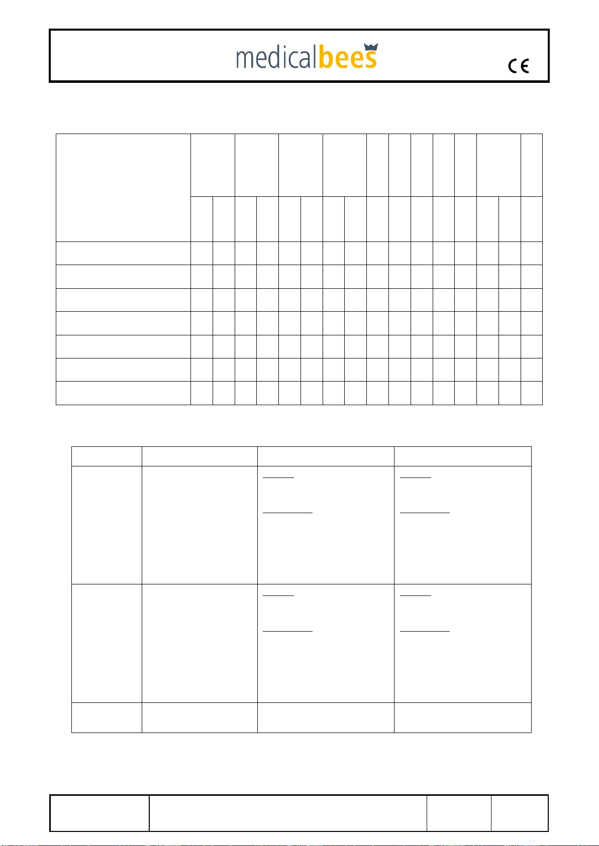
1.6.2 Combinability of individual beesystem components
System overview
Drilling and
reaming machine
Drilling machine
4° oscillating saw,
Synthes
2° oscillating saw,
Synthes
Oscilla-ting saw
Stryker 2°/4°
Straight saw
Styker 2°/4°
Straight saw
Synthes 2°/4°
Reciprocating saw
Sternum saw
Sternum saw with
keyless chuck
Oscillating
reaming machine
Item No.
Accessories
Name
F-30-100-00
F-31-100-00
F-30-150-00
F-31-150-00
F-30-300-00
F-31-300-00
F-30-301-00
F-31-301-00
F-31-310-00
F-31-311-00
F-40-100-00
F-40-101-00
F-40-110-00
F-40-111-00
F-30-400-00
F-30-600-00
F-30-601-00
F-31-601-00
F-31-700-00
F-30-900-00
Power Pack
x
x
x
x
x
x
x
x
x
x
x
x
x
x
x
x
F-30-900-50
Charging unit (1 charging
slot)
x
x
x
x
x
x
x
x
x
x
x
x
x
x
x
x
F-30-900-51
Charging unit (2 charging
slots)
x
x
x
x
x
x
x
x
x
x
x
x
x
x
x
x
F-30-900-52
Charging unit (4 charging
slots)
x
x
x
x
x
x
x
x
x
x
x
x
x
x
x
x
F-30-900-53
Country-specific plug
x
x
x
x
x
x
x
x
x
x
x
x
x
x
x
x
F-30-900-54
Country-specific plug
x
x
x
x
x
x
x
x
x
x
x
x
x
x
x
x
F-30-900-55
Country-specific plug
x
x
x
x
x
x
x
x
x
x
x
x
x
x
x
x
F-30-900-56
Country-specific plug
x
x
x
x
x
x
x
x
x
x
x
x
x
x
x
x
F-30-900-57
POAG cable for charging
units
x
x
x
x
x
x
x
x
x
x
x
x
x
x
x
x

0483
Data
05 February 2021
IFU GA-001-02
Revision
03
Page
11 of 88
System overview
Drilling and
reaming machine
Drilling machine
4° oscillating saw,
Synthes
2° oscillating saw,
Synthes
Oscilla-ting saw
Stryker 2°/4°
Straight saw
Styker 2°/4°
Straight saw
Synthes 2°/4°
Reciprocating saw
Sternum saw
Sternum saw with
keyless chuck
Oscillating
reaming machine
Item No.
Accessories
Name
F-30-100-00
F-31-100-00
F-30-150-00
F-31-150-00
F-30-300-00
F-31-300-00
F-30-301-00
F-31-301-00
F-31-310-00
F-31-311-00
F-40-100-00
F-40-101-00
F-40-110-00
F-40-111-00
F-30-400-00
F-30-600-00
F-30-601-00
F-31-601-00
F-31-700-00
F-30-100-10
Kirschner wire chuck (for
drill/ream)
x
x
F-30-100-15
Kirschner wire chuck (for
standard)
x
x
F-30-100-19
Extension for Kirschner
wire chuck
x
x
x
x
F-30-100-25
Adapter for radiolucent
x
x
x
x
F-30-100-50
AO chuck, small
x
x
x
x
F-30-100-51
AO chuck, big
x
x
x
x
F-30-100-52
1/4 " attachment
x
x
x
x
F-30-100-53
Hudson chuck
x
x
x
x
F-30-100-54
Harris chuck
x
x
x
x
F-30-100-55
Hexagonal chuck, SW6
x
x
x
x
F-30-100-56
DIN-clutch for tools
x
x
x
x
F-30-100-57
Zimmer Hall Chuck
x
x
x
x
F-30-100-60
Jacobs drill chuck, small
x
x
x
x
F-30-100-61
Jacobs drill chuck, big
x
x
x
x
F-30-100-62
Rohm drill chuck
x
x
x
x
F-30-100-63
Quick-action chuck with
lock
x
x
x
x
F-30-100-64
Quick-action chuck without
lock
x
x
x
x
F-30-100-65
Albrecht quick action chuck
x
x
x
x
F-30-100-66
Large drill chuck
x
x
x
x
F-30-400-05
Keyless top for sternum
x
F-30-400-10
XL Keyless top for sternum
x

0483
Data
05 February 2021
IFU GA-001-02
Revision
03
Page
12 of 88
System overview
Drilling and
reaming machine
Drilling machine
4° oscillating saw,
Synthes
2° oscillating saw,
Synthes
Oscilla-ting saw
Stryker 2°/4°
Straight saw
Styker 2°/4°
Straight saw
Synthes 2°/4°
Reciprocating saw
Sternum saw
Sternum saw with
keyless chuck
Oscillating
reaming machine
Item No.
Accessories
Name
F-30-100-00
F-31-100-00
F-30-150-00
F-31-150-00
F-30-300-00
F-31-300-00
F-30-301-00
F-31-301-00
F-31-310-00
F-31-311-00
F-40-100-00
F-40-101-00
F-40-110-00
F-40-111-00
F-30-400-00
F-30-600-00
F-30-601-00
F-31-601-00
F-31-700-00
F-30-900-10
Lubrication stand
x
x
x
x
x
x
x
x
x
x
x
x
x
x
x
x
F-30-900-20
Sterile funnel
x
x
x
x
x
x
x
x
x
x
x
x
x
x
x
x
F-30-900-60
Spray oil of the Beesystem
GmbH
x
x
x
x
x
x
x
x
x
x
x
x
x
X
x
x
F-30-900-61
Oil Pen
x
x
x
x
x
x
x
x
x
x
x
x
x
X
x
x
F-30-900-70
Universal spray adapter
(for all machines)
x
x
x
x
x
x
x
F-30-900-72
Spray adapter for drilling
machine
(for F-30-100-00 / F-30-
150-00)
x
x
F-30-900-74
Spray adapter for saws
(for F-30-400-00 / F-30-
600-00 / F-30-601-00)
x
x
x
F-30-900-78
Spray adapter for drilling
machine
(for F-30-100-00 / F-30-
150-00)
x
x
F-30-910-05
Lid for cleaning and
sterilisation tray with a lock
x
x
x
x
x
x
x
x
x
x
x
x
x
x
x
x
F-31-910-13
Cleaning and sterilisation
tray (1 machine) with lid,
bare grip –for beesystemI
and beesystemII
x
x
x
x
x
x
x
x
x
x
x
x
x
x
x
x
F-31-910-18
Cleaning and sterilisation
tray (2 machines) with lid,
bare grip - for beesystemI
and beesystemII
x
x
x
x
x
x
x
x
x
x
x
x
x
x
x
x
F-30-910-30
Universal rinsing adapter
(for all machines)
x
x
x
x
x
x
x
x
x
F-30-910-31
Rinsing adapter for drilling
machine
x
x
x
x
F-30-910-33
Rinsing adapter for
reciprocating- sternum saw
(for F-30-400-00 / F-30-
600-00 / F-30-601-00)
x
x
x
F-30-910-40
Rinsing set
x
x
x
x
X
x
x
x
x
x
x
x
x
x
x
x
F-30-910-42
beesystem chuck: Miele /
Stielco / Webeco
x
x
x
x
x
x
x
x
x
x
x
x
x
x
x
x
F-30-910-43
beesystem adapter
Belomed
x
x
x
x
x
x
x
x
x
x
x
x
x
x
x
x
F-30-910-44
beesystem adapter
Maquet / MediKomp /
Getinger
x
x
x
x
x
x
x
x
x
x
x
x
x
x
x
x
F-30-910-50
Cleaning brushes - set
x
x
x
x
x
x
x
x
x
x
x
0483
Data
05 February 2021
IFU GA-001-02
Revision
03
Page
13 of 88
1.6.3 Recommended cutting tool
Third-party products
(Recommendations of the Medica-Bees
GmbH Company; not included in the list of
products)
Drilling and
reaming machine
Drilling machine
4° oscillating
saw, Synthes
2° oscillating
saw, Synthes
Oscilla-ting saw
Stryker 2°/4°
Straight saw
Styker 2°/4°
Straight saw
Synthes 2°/4°
Reciprocating
saw
Sternum saw
Sternum saw
with keyless
chuck
Oscillating
reaming machine
F-30-100-00
F-31-100-00
F-30-150-00
F-31-150-00
F-30-300-00
F-31-300-00
F-30-301-00
F-31-301-00
F-31-310-00
F-31-311-00
F-40-100-00
F-40-101-00
F-40-110-00
F-40-111-00
F-30-400-00
F-30-600-00
F-30-601-00
F-31-601-00
F-31-700-00
3-flute spiral drill bit
(Synthes Company)
x
x
x
x
Saw blades with Synthes
joint
x
x
x
x
x
Saw blades with Stryker
joint
x
x
x
x
x
x
Saw blades of the Gomina AG Company
x
x
x
x
x
x
x
Saw blades of the Risa GmbH Company
x
x
x
x
x
x
x
x
x
x
x
Saw blades of the company mahe medical
GmbH
x
x
x
x
x
x
x
Hol reamers of the Richard Wolf GmbH
Company
x
Saw blades of the following manufacturers are recommended with their dimensions and connections.
Gomina AG Company
mahe medical GmbH
Risa GmbH Company
Synthes connection
Oscillating saw
70 mm long, 25 mm wide, 0.90 –1.47 mm
thick
70 mm long, 19 mm wide, 0.90 –1.47 mm
thick
90 mm long, 25 mm wide, 0.90 –1.47 mm
thick
90 mm long, 19 mm wide, 0.90 –1.47 mm
thick
90 mm long, 12 mm wide, 0.90 –1.47 mm
thick
90 mm long, 12-19mm wide, 0.90 –1.47 mm
thick
Crossed teeth
48-95mm long, 22-50mm wide, 0.4-1.2 mm thick
18-68mm long, 4.0-15 mm wide, 0.4-0.6 mm thick
Diamond-ground teeth
90-120 mm long, 25-31 mm wide, 0.89 mm-1.47 mm
thick
50-110 mm long, 25 mm wide, 0.89mm-1.47 mm thick
90-120 mm long, 19-22 mm wide, 0.89 mm-1.47 mm
thick
50-100 mm long, 13-19 mm wide, 0.89 mm-1.47 mm
thick
Stryker 6
connection
oscillating saw
70 mm long, 25 mm wide, 0.90 –1.47 mm
thick
70 mm long, 19 mm wide, 0.90 –1.47 mm
thick
90 mm long, 25 mm wide, 0.90 –1.47 mm
thick
90 mm long, 19 mm wide, 0.90 –1.47 mm
thick
90 mm long, 12 mm wide, 0.90 –1.47 mm
thick
90 mm long, 12-19mm wide, 0.90 –1.47 mm
thick
Crossed teeth
48-95mm long, 22-50mm wide, 0.4-1.2 mm thick
18-68mm long, 4.0-15 mm wide, 0.4-0.6 mm thick
Diamond-ground teeth
90-120 mm long, 25-31 mm wide, 0.89 mm-1.47 mm
thick
50-110 mm long, 25 mm wide, 0.89mm-1.47 mm thick
90-120 mm long, 19-22 mm wide, 0.89 mm-1.47 mm
thick
50-100 mm long, 13-19 mm wide, 0.89 mm-1.47 mm
thick
Crossed teeth
48-95mm long, 22-50mm wide, 0.4-1.2 mm thick
18-68mm long, 4.0-15 mm wide, 0.4-0.6 mm thick
Diamond-ground teeth
90-120 mm long, 25-31 mm wide, 0.89 mm-1.47 mm
thick
50-110 mm long, 25 mm wide, 0.89mm-1.47 mm thick
90-120 mm long, 19-22 mm wide, 0.89 mm-1.47 mm
thick
50-100 mm long, 13-19 mm wide, 0.89 mm-1.47 mm
thick
Stryker connection
n.a.
60mm long, 10mm wide, 0,6mm thick
80mm long, 10mm wide, 1,00mm hick
60 mm long, 10 mm wide, 0.6 –1.47 mm thick
80 mm long, 10 mm wide, 1.00 –1.47 mm thick
0483
Data
05 February 2021
IFU GA-001-02
Revision
03
Page
14 of 88
1.6.4 Storage and Transport
All the products, traded by us on the market, are delivered as non-sterile and shall thus demand
processing before use. The medical bees GmbH Company recommends single use of corresponding
drilling and cutting tool.
On product safety grounds, only original packaging systems shall be used for shipment and transport.
If this is no longer available, please contact the Medical bees GmbH Company.
The environmental conditions for storage and transport are addressed in this User’s Manual. Before
disposal or return transport to the medical bees GmbH Company, the devices/handpieces, as well as
the chucks, shall undergo the complete procedure of clinical processing for protection against
infections. In addition, the products shall appropriately be marked as either „hygienically safe" or “not
decontaminated".
1.6.5 Disposal
Defective devices can mostly be repaired, see the User’s Manual for this issue. The devices contain
lithium-ion batteries (Li-ion = chem. Symbol of harmful substance) and, on grounds relating to the
protection of the environment, shall thus be properly disposed. Battery disposal shall comply with
national laws or with the European battery directive: 2006/66/EC, as well as with the Waste of
Electrical and Electronic Equipment (WEEE) directive - 2002/96/EC.
A special care shall be taken here with regards to fire, explosion and burn hazards. It must be kept in
mind that battery cells shall not be damaged, opened, torn, shorted, crushed or allowed in contact with
fluids.
Before disposal, the devices/handpieces, as well as the chucks, shall undergo the complete procedure
of clinical processing for protection against infections. The device shall not be disposed of with the
household waste.
1.6.6 Guarantee
The guarantee for the devices and accessories shall be cancelled in case of their unintended use
and/or inappropriate operation, storage or transport. The Manufacturer shall assume no responsibility
for damages, which may arise from improper operation of the system or from its maintenance provided
by unauthorised service stations

0483
Data
05 February 2021
IFU GA-001-02
Revision
03
Page
15 of 88
2 Operation of the device
2.1 Description of the controls, indication functions and
symbols
2.1.1 Drilling / reaming machine (F-31-100-00)
1 Release sleeve for attachments
2 Trigger for speed regulation
3 Slider for switching in the right direction, locking (safety position), left-hand rotation
4 Locking latches
5 Switch lever to switch oscillating mode ON or OFF
6Rotating ring for the DRILL mode or REAM mode
7Sight glass for LED indications and lighting
The slider in the middle position
→INTERLOCK / SAFETY
POSITION
The device cannot be
unintentionally started
The slide retracted →CW rotation
The slide extended →CCW
rotation
The oscillating mode is on
The oscillating mode is off
1
2
6
3
5
7
4

0483
Data
05 February 2021
IFU GA-001-02
Revision
03
Page
16 of 88
2.1.2 Drilling machine (F-31-150-00)
1 Release sleeve for attachments
2 Trigger for speed regulation
3 Slider for switching in the right direction, locking (safety position), left-hand rotation
4 Locking latches
5 Switch lever to switch oscillating mode ON or OFF
6Sight glass for LED indications and lighting
The slider in the middle position
→INTERLOCK / SAFETY
POSITION
The device cannot be
unintentionally started
The slide retracted →CW rotation
The slide extended →CCW
rotation
The oscillating mode is on
The oscillating mode is off
4
1
3
2
5
6

0483
Data
05 February 2021
IFU GA-001-02
Revision
03
Page
17 of 88
2.1.3 Oscillating saws Synthes AO connection (F-31-300-00; F-31-301-
00)
1 Locking ring for saw blade tension
2 Trigger for speed regulation / oscillation frequency
3 Slider for switching ON, locking (safety position), ON
4 Locking latches
5 Switch lever to switch the I “Normal” and II “Quick” mode
6 Unlocking sleeve for setting the saw head in 45° steps
7Sight glass for LED indications and lighting
The slider in the middle
position →INTERLOCK /
SAFETY POSITION
The device cannot be
unintentionally started
Frequency/CPM set at step
“I”
Frequency/CPM set at step
“II”
1
2
3
4
5
6
7

0483
Data
05 February 2021
IFU GA-001-02
Revision
03
Page
18 of 88
2.1.4 Oscillating saw Stryker Sawblade connection (F-31-310-00/F-31-
311-00)
1 Locking ring for saw blade tension
2 Trigger for speed regulation / oscillation frequency
3 Slider for switching ON, locking (safety position), ON
4 Locking latches
5 Switch lever to switch the I “Normal” and II “Quick” mode
6 Unlocking sleeve for setting the saw head in 45° steps
7Sight glass for LED indications and lighting
The slider in the middle
position →INTERLOCK /
SAFETY POSITION
The device cannot be
unintentionally started
Frequency/CPM set at step
“I”
Frequency/CPM set at step
“II”
1
2
3
4
5
6
7
0483
Data
05 February 2021
IFU GA-001-02
Revision
03
Page
19 of 88
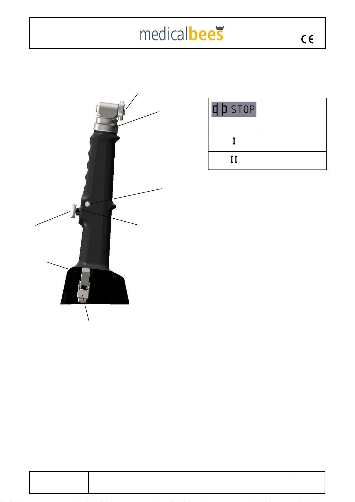
2.1.5 Straight Oscillating saw Stryker Sawblade connection (F-40-100-
00/F-40-101-00)
1 Locking knob for saw blade tension
2 Trigger for speed regulation / oscillation frequency
3 Slider for switching ON, locking (safety position), ON
4 Locking latches
5 Switch lever to switch the I “Normal” and II “Quick” mode
6 Unlocking sleeve for setting the saw head in 45° steps
7Sight glass for LED indications and lighting
The slider in the middle
position →INTERLOCK /
SAFETY POSITION
The device cannot be
unintentionally started
Frequency/CPM set at step
“I”
Frequency/CPM set at step
“II”
1
2
3
4
5
6
7

0483
Data
05 February 2021
IFU GA-001-02
Revision
03
Page
20 of 88
2.1.6 Straight Oscillating saw Synthes AO connection (F-40-110-00/F-40-
111-00)
1 Locking ring for saw blade tension
2 Trigger for speed regulation / oscillation frequency
3 Slider for switching ON, locking (safety position), ON
4 Locking latches
5 Switch lever to switch the I “Normal” and II “Quick” mode
6 Unlocking sleeve for setting the saw head in 45° steps
7Sight glass for LED indications and lighting
The slider in the middle
position →INTERLOCK /
SAFETY POSITION
The device cannot be
unintentionally started
Frequency/CPM set at step
“I”
Frequency/CPM set at step
“II”
1
2
3
4
5
6
7
This manual suits for next models
1
Table of contents


