Schulze Air press-4 X User manual

Instruction manual
Version 11.01
Pneumatic press
Air press-4 X
automatic
Version 11.01
1/26

1. Introduction
1.1 Content
1. Introduction 02
1.1 Content 02
1.2 Illustration of the heat press 03
1.3 Technical data 04
1.4 Accessory 05
1.5 xchangeable heating plates 05
1.6 xchangeable base plates 05
1.7 Safety arrangements of the press 06
1.8 Safety arrangements at the workspace 06
2. Initiation 07
2.1 Tips for transport 07
2.2 Installation of the heat press 07
2.3 Connection of the press to compressed air 10
2.4 Power supply 10
2.5 Initiation of the heat press 11
2.6 Automatic / Manual 11
3. Working wit t e eat press 12
3.1 Programming of electronic devices 12
3.2 Rodzaje programu trybu automatycznego 12
3.3 Counter
3.4 rror reports 12
3.5 Application range and sample adjustments of the heat press 13
3.6 Pressure settings 13
3.7 xchanging the heating plate 14
3.8 xchanging the base plate 14
3.9 Safety frame 15
3.10 Cooling system (optional) 15
3.11 Screen printing mounting adjustment (optional) 16
4. Maintenance 16
4.1 Daily Maintenance 16
4.2 Replacing the main fuse 17
4.3 Replacing the power supply 17
4.4 Replacing the fuse in the power supply 18
4.5 Replacing the electronic devices 18
4.6 Instrukcja wymiany klawiaturki elektroniki
4.7 Instrukcja wymiany układu sterującego
4.8 Instrukcja wymiany przekaźnika
4.9 Replacing the silicon mat 19
4.10 Replacing the thermal fuse 19
4.11 Replacing the thermo couple 19
4.12 Troubleshooting 20
4.13 Connection diagram 21
4.14 Controlling of the pneumatics 22
4.15 Certificate of manufacturer 23
4.16 Testing Report 24
4.17 C-Conformance-Declaration 24
Version 11.01
2/26

1.2 Illustration of t e eat press
1. Heating plate with safety frame
2. mergency button
3. Switch manual / automatic
4. Activation safety frame
5. Counter switch
6. Program change switch
7. Counter display
8. Pressure adjustment
9. Pressure gauge
10. Control lamp
11. Fixation screw
12. Control desk
13. Spiral tube
14. Base plate with silicon rubber
15. Cover plate
16. Rotation of the base plate to the left
17. Display of the electronic devices
18. Switch START
19. Rotation of the base plate to the right
20. Temperature and time adjustment
Version 11.01
3/26

21. Metal case
22. Air filter with water separator
23. Main fuse
24. Main switch
25. Retainer
26. Power cable
27. Compressed air connection
28. lectric case
1.3 Tec nical data
Dimensions of the press with metal case: 182 x 146 x 146 cm
Working area: 40 x 50 cm / 38 x 50 cm
Weight: 210 kg
Operating voltage: 230 VAC
Rated power 40 x 50 cm: 2,3 kW
Rated power 38 x 45 cm: 2,0 kW
Air requirement per cycle: 7,2 l
Temperature range: 0 – 220° C
Time setting: 1 sec – 19:59 min
Max. pressure: 6 bar
Pressure output at 6 bar: ca. 2490 kg
Main fuse: 12A
Version 11.01
4/26

1.4 Accessory
The Air press-4 X can be equipped with complementary accessory.
1. Cooling system
2. Screen print frame mounting
3. Laser with mounting
1.5 Exc angeable eating plates
For the press there are several heating plates available.
The instruction for the exchange you can find in chapter 3.7.
1. Heating plate 70 x 90 cm
2. Heating plate 40 x 50 cm
3. Heating plate 38 x 45 cm
1.6 Exc angeable base plates
For the press there are several base plates available.
The instruction for the exchange you can find in chapter 3.8.
1. Membrane plate 70 x 90 cm
2. Base plate 40 x 50 cm
3. Base plate 38 x 45 cm
4. Trapezoid plate
5. Base plate 25 x 25 cm
6. Base plate 20 x 20 cm
7. Base plate 10 x 45 cm
Version 11.01
5/26

1.7 Safety arrangements of t e eat press
The Air press-4 X is equipped with different safety arrangements, to make a safe usage possible.
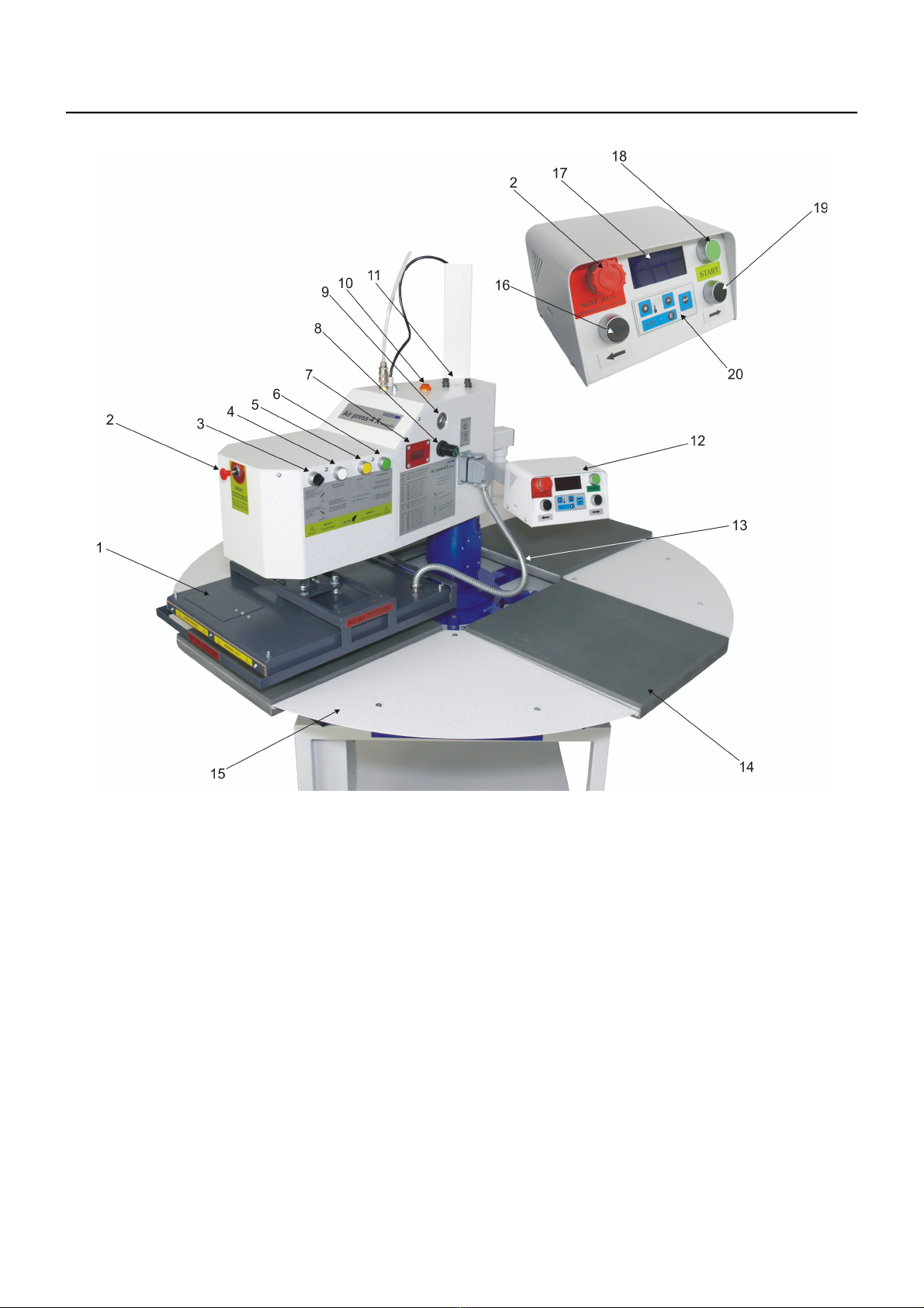
Main fuse 12A
The main fuse 12A is placed in the pivoting upper part of the heat press. In case of overcharge, the main fuse prevents the heat press
from getting damaged.
Once the fuse was activated, it has to be replaced. The instruction for replacing the main fuse can be found in chapter 4.2.
Fuse 1,6A
This fuse is placed in the 12VAC power supply in the upper part of the heat press. It saves the 12VAC circuit of an overcharge. Once the
fuse was activated, it has to be replaced. The instruction for the exchange you can see in chapter 4.4.
T ermal fuse
The thermal fuse is placed directly on the heating plate and it stops the power supply if the temperature exceeds 260°C. If this fuse is
activated, the temperature sinks down to 90°C. After that the power supply gets activated again and the temperature of the heating plate
rises and you can work with the press again. Certainly you need to install a new thermal fuse within the next days. The instruction for the
replacement of the thermal fuse can be found in chapter 4.10.
Safety valve
The safety valve 6.0 bar is placed at the pressure pipe in the press. I the pressure should exceed 6.0 bar, the valve will be activated
automatically.
Automatic switc -off
If the press doesn't get opened within 10 seconds after the pressing progress, the heating element switches off automatically, to avoid fire
danger.
Safety frame
The safety frame is located at the heating plate. If it should be activated, the Pressing process will be suspended.
Emergency switc
In cases of emergency, press one of the two emergency switches situated at the front of the press and on the control desk.
After turning the emergency switch on, it should be turned off in order to continue pressing.
1.8 Safety arrangements at t e workspace
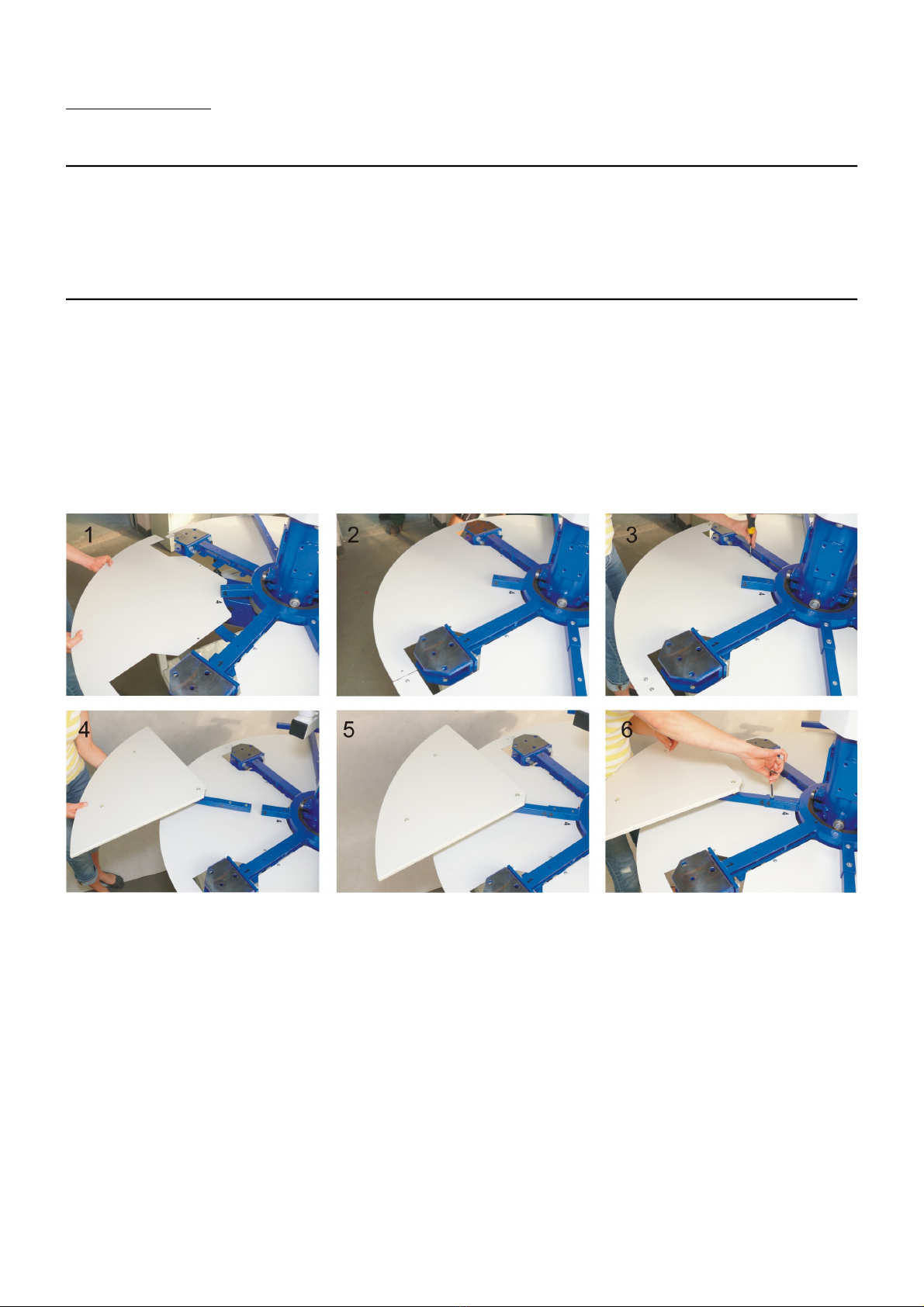
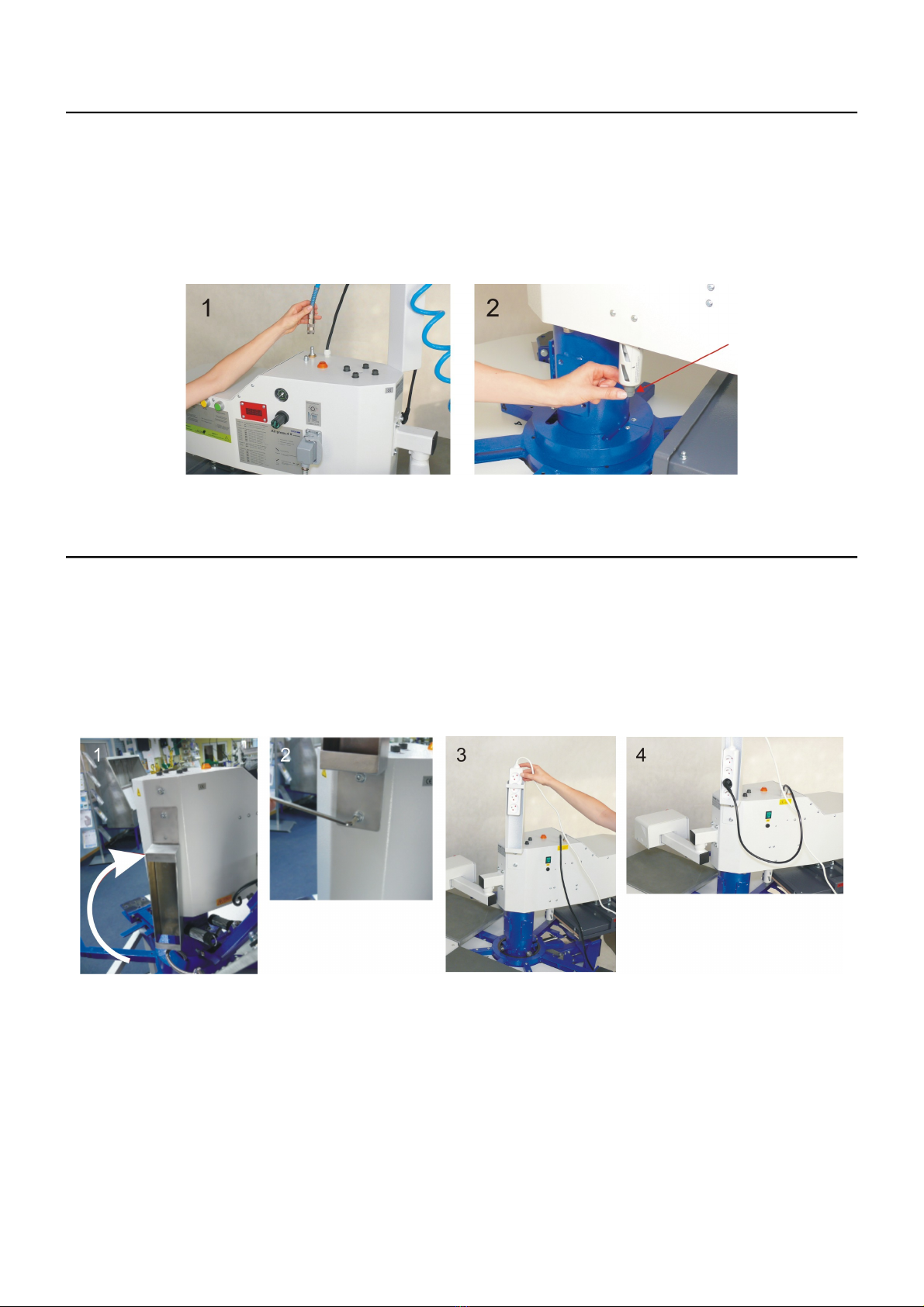
Set-up and installation of t e eat press
The set-up and installation of the press has to be done under supervision of an authorized person. The installation has to be done by 2 or
more persons following the instructions of this manual.
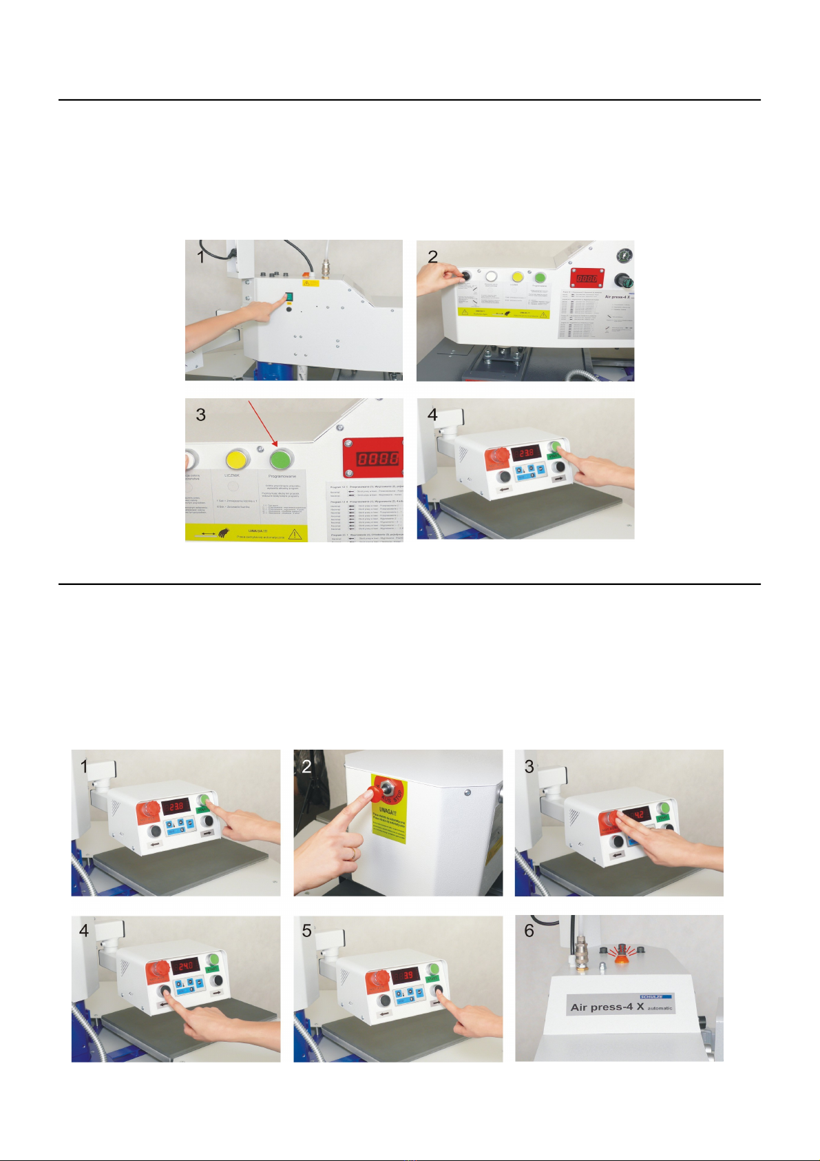
Testing t e eat press
After a correct installation of the press it is important to ensure that the press works properly, isn't damaged and has no safety defects. The
testing can only be done by the employer or other authorized persons and is mandatory to guarantee correct installation and safe usage of
the press. The testing should be protocoled.
If any irregularities regarding functionality or safety are found during the testing, these have to been noted and reported to Walter Schulze
GmbH in written form within 7 days. Until clarification the press can not be used.
Information and Education
According to § 81 industrial relations law and § 14 employment protection law the employer has to make arrangements to give all
information about the function and the range of application to the user.
In particular the user needs to be acquainted with the complete manual and be explicitly informed of the dangers of working with the press.
The details have to be explained in a coherent form and language.
Safety distance and ventilation
The press has to be installed at a place which gives enough space on both sides to put the material on.
The space in front of the press has to be wide enough to let nothing disturb the user at work.
Using the press with certain materials may create a strong smell. That’s why the user should evaluate the need for a ventilation system at
the workplace.
Safety instruction
•The press should only be used by trained personal after notice of this manual.
•Only one person is allowed to work on the press at a time.
•Beware of heating plate – risk of burns.
•Attention, the press opens automatically – keep the safety clearance.
•The plug has to be pulled out of the power outlet while maintenance.
•The safety frame has always to be connected.
•Caution: please do not connect this press to any other outlet (socket) than those equipped with ground-fault protection LCB (earth
leakage circuit breaker).
Version 11.01
6/26

2. Initiation
2.1 Tips for transport
The SCHULZ Air press-4 X is covered in protective foil for transport and fixed onto the pallet. Right after the receiving you should check
if the foil and the press are in good condition. Later on, if you have to send the press somewhere, we ask you to fix the press in the same
way on the pallet. The press has to be cold for the transport.
2.2 Installation of t e eat press
Remove the protective foil and release the pedestal of the pallet. The pedestal is equipped with 4 wheels with brakes. The brakes have to
be tightened to avoid dislocation of the press. Lifting and moving of the press has to be done by at least 4 persons. The press with
pedestal weighs 210 kg.
The base plates, heating plate and cover plates have to be mounted after the transport.
Assembly instruction of the handles and safety plates:
1. Put the cover plates ( very bar has a number, please mind that) (p oto 1-2)
2. Screw the cover plates together (p oto 3)
3. Put the cover plates in the corresponding slot ( very bar has a number, please mind that) (p oto 4-5)
4. Screw the cover plates together (p oto 6)
Version 11.01
7/26

Assembly instruction of the base plates:
1. Put the base plates in place (p oto 1-2)
2. Tighten the base plates (p oto 3-4)
Assembly instruction of the heating plate:
1. Put the heating plate on the base plate (p oto 1)
2. Pick up the heating plate and then put into the pin (p oto 2)
3. Screw the heating plate (p oto 3)
4. Connect the heating plate with the press (p oto 4-5)
Version 11.01
8/26

2.3 Connection of t e press to compressed air
The Air press-4 X is a pneumatic press, which has to be connected to compressed air. The maximum pressure inside the press must not
exceed 6 bar. The air has to be dry and clear of oil. If required you may employ additional filter and drier. The port for the compressed air
at the press is equipped with a quick connect (p oto 1).
After working with the press disconnect the compressed air. So the container with the condensed water will empty automatically. If you
compressed air system isn't equipped with an air drier, you need to check the container every 4 hour and empty it. Therefore press the
knob (p oto 2) upwards.
To remove the container, disconnect the compressed air first. Push the container up and turn it to the left, now you may remove it. If there
is oil in the container you need to switch off the press at once and repair the compressor. Oil in the system may be damage the press.
2.4 Power supply
Die Air press-4 X has to be connected to a voltage of 230VAC/ 50Hz. The press is equipped with a plug. Make sure that the power outlet
is in the right condition and that the grounding is connected to the power outlet. Turn and fasten the the retainer (p oto 1-2). An
extension cable 230VAC must be fasten in the retainer above the press (p oto 3-4). The laying and connection the power cable and the
compressed air pipe has to be done above the press.
Caution: please do not connect this press to any other outlet (socket) than those equipped with ground-fault protection LCB (earth
leakage circuit breaker).
Version 11.01
9/26

2.5 Initiation of t e eat press
The press should only be used by trained personal after notice of this manual. Before the first start up m ake sure that the power outlet is
in the right condition and that the grounding is connected to the power outlet. Assemble the press before you work with it (chapter 2.2).
The press can be turned on with the green dip-switch (p oto 1). If the green switch glows the press heats up to the adjusted
temperature. The press heats up to the preset temperature. The press must be open while heating up. The device can operate in two
modes – automatic and manual. The mode must be set before the press starts the pressing process (picture 2). One of the operating
programmes is to be selected next (picture 3). In order to initiate the process of pressing, push the green START button on the control
desk (picture 4). The heat platen lowers itself down and presses against the lower platen. After the pressing process finishes, the press
opens automatically. When the press is not used, switch it off and unplug it.
2.6 Automatic / Manual
The switch on the right side of the press allows for the change of the operating mode.
In t e manual mode the START button must be pushed every time the heat platen movement is to be initiated (picture 1).
In t e automatic mode the buttons for the 90º left or right turn of the lower platens must be pushed in order to initiate the heat platen
movement (pictures 4-5).
The yellow warning light on the press is on when the lower platens are turning (picture 6).
In both the automatic and the manual mode, the process of pressing may be stopped by pushing the START button again (picture 1) or by
pressing one of the two emergency switches (picture 2-3).
The number of lower platen turns depends on the number of times the lower platen left/right turn button is pushed.
If the 0..0 program in the automatic mode is selected, the process of pressing will start automatically. If other programs are used, the lower
platen will stop and the pressing process will begin after pushing the START button.
Version 11.01
10/26

3. Working wit t e eat press
3.1 Programming t e electronic devices
After switching on the press, the current temperature is shown is shown on the display and the press heats up.
C ange settings:
1. The programming mode shows up when you press Setup for about 5 seconds, until the L D1 blinks up.
2. L D1 blinks and the programmed temperature shows on the display The programming mode is activated.
3. The temperature gets programmed with button “+” and “-”.
4. Press Setup shortly.
On the display you now can see the programmed time. You can adjust the time by pushing Button “+” and “-”.
5. Press Setup shortly to save the changes and leave the programming mode.
All settings are saved.
Control of adjusted temperature
If you want to control which temperature is adjusted at the
moment, press button “+”. The temperature shows up on the
display.
Control of adjusted time
If you want to control which time is adjusted at the moment, press
button “-”. The time shows up on the display.
3.2 Automatic mode types
Air Press-4X operates using five different programs. Push the green “PROGRAM” button to select a program. One of the following
programs may be chosen:
0 0 - automatic mode: each movement of the press must be preceded by pushing the START button or the lower platen turn button
12 1 - pre-pressing – single pressing: once the lower platen turn button is pushed, the work platen will position itself under the heat platen
and pre-pressing will start. When the press is opened, the lower platen turns right. Pushing the lower platen turn button again
makes the work platen return under the heat platen which lowers itself down and the transfer is pressed;
12 4 – pre-pressing – pressing – 4 items: once the START button is pushed, there begins the process of pre-pressing on the work platen
located under the heat platen. The pre-pressing on other platens takes place after every push of the platen turn button. The
pressing process begins right after the whole cycle of pre-pressing. ach instance of pressing must be initiated by pushing the
lower platen turn button.
23 1 - pressing – single repressing: once the lower platen turn button is pushed, the work platen will position itself under the heat platen
and pressing will start. When the press is opened, the lower platen turns right. Pushing the lower platen turn button again makes
the work platen return under the heat platen which lowers itself down and the transfer is repressed;
23 4 - pressing – repressing – 4 items: once the START button is pushed, there begins the process of pressing on the work platen located
under the heat platen. The pressing on other platens takes place after every push of the platen turn button. The process of
repressing begins right after the whole cycle of pressing. ach instance of repressing must be initiated by pushing the lower platen
turn button.
Version 11.01
11/26

3.3 Counter
Air Press-4 X is equipped with a transfer counter. The number of transfers is displayed on the screen. Use the yellow button (picture 1) to
reset the counter or deduct one unit from the counter’s record. Additionally, the screen (picture 2) displays the number of the selected
program. The transfer counter operates only in 0..0 mode.
The display shows the stage in the cycle of a given program or, when operating in 0..0 mode, the number of transfers made. The screen
also displays the following alarm codes:
7777 – one of the two emergency switches is turned on during the start of the machine or a safety frame has been activated
9999 – one of the two emergency switches is turned on
3.4 Error reports
The electronic devices of the Airpress4 control the main functions of the press.
Here is a list of possible messages:
RR.1 – No connection of the electronic devices to the temperature sensor. (Temperature sensor defect/ cable not connected)
RR.2 – Connection of electronic devices and temperature sensor bypassed. (Temperature sensor defect/)
RR.3 – Resistor of temperature sensor too low. The temperature range of the electronic devices is deceeded.
RR.4 – Resistor of temperature sensor too high. The temperature range of the electronic devices exceeded.
RR.5 – No temperature rise within 3 minutes even if heating element is switched on. (Temperature fuse is defect)
RR.6 – No reduction of the temperature within 3 minutes even if heating element is turned off. (Power relay CRYDOM is defect)
RR.7 – Temperature too high, over 230°C (Power relay CRYDOM is defect)
RR.3 and RR.4 can occur if the electronic devices are not programmed properly.
3.5 Application range and sample adjustments of t e press
This press is used to put transfers and transfer films on textiles. To get good achievements, get in contact with the producer of the textiles.
Here are some settings:
Film Flex 150°C – 160°C Time 15 Seconds
Film Flex S 155°C – 160°C Time 15 Seconds
Film A-Flex 155°C – 160°C Time 15 Seconds
Film Flock 160°C – 180°C Time 15 Seconds
Sublimation Film 190°C – 205°C Time 50 Seconds
All information is supplied without liability, please run your own testing before production.
Version 11.01
12/26

3.6 Pressure settings
Wit this press you can change the pressure setting .
After every change of the pressure settings, close the heat press to check the new settings.
Damages, w ic arise from to muc pressure, are excluded from t e guarantee.
To adjust the pressure do the following:
1. Take the pressure reading. (p oto 3)
2. To alter the pressure pull the knob to you. (p oto 1)
◦Rotating the knob to the right will increase the pressure
◦Rotating the knob to the left will decrease the pressure
3. To retain the setting push the knob to the press again.
4. Test the pressure (p oto 2)
The pressure reading you may take at the top on the right.
Plate 38 x 45 cm ~ 2,0 bar (max. 4,0 bar)
Plate 40 x 50 cm ~ 2,5 bar (max. 4,5 bar)
The pressure reading you may take at the top on the right.
1,0 bar - ca. 415 kg
2,0 bar - ca. 830 kg
3.0 bar - ca. 1245 kg
4.0 bar - ca. 1660 kg
5,0 bar - ca. 2075 kg
6.0 bar - ca. 2490 kg
If you alter the pressure to a setting higher than 6 bar, a safety valve will be activated. In this case you have to reduce the pressure.
Version 11.01
13/26

3.7 Exc anging t e eating plate
To exchange the heating plate, the press must be disconnected from electricity and cold.
Now disconnect the spiral tube plug of the heating plate. (p oto 1-2). Loosen fixation screw with a wrench (p oto 3). Take hold of the
plate and put it down carefully on the base plate (p oto 4-5). Take the heating plate carefully and put it on a soft underground, because
the Teflon cover should not be damaged. Then take the new heating plate and tighten it with the wrench. Connect the heating plate and
the safety frame with the press again.
T e eating plate can not be turned.
3.8 Exc anging t e base plate
If you want to exchange the base plate you have to loosen the fixation screw s (p oto 1). Then you can take of the base plate (p oto 2).
After exchanging the base plate, tighten the fixation screw again (p oto 1).
The base plate can not be turned 90 degrees.
Version 11.01
14/26

3.9 Safety frame
The Air press-4 X is equipped with an safety frame (p oto 1). The safety frame guards against burnings. If you should touch the safety
frame while it's going down (p oto 2), the process will be interrupted at once. In that case you have to press the activation button again
(p oto 3). Thereby you also confirm, that it is still safe to work with the press.
3.10 Cooling System (optional)
The cooling system is run with water. To fill the cooling system with water, do the following:
1. Turn off the press and pull the disconnect the power.
2. Unscrew both air bleed valves and tilt the cooling plate slightly up (p oto 1).
3. Pull the plug of the cooling system and remove the cover of the pump (p oto 2).
4. Take out the connecting tube (p oto 3).
5. Open the valve for filling the system (p oto 4).
6. Fill the system with tap water by means of a funnel or a tube, until the water comes out the air bleed valves (p oto 5).
7. Close the valve below and let the water out of the tube.
8. Screw the air bleed valves with caution manually in place.
9. Place carefully the tube into the housing below.
10. Screw the cover in place.
Version 11.01
15/26

3.11 Screen printing mounting adjustment (optional)
At the Airpress4 you can mount a screen print frame directly over one of the base plates. In this way you can print one colour directly on
the press. To work comfortably with the frame you can adjust the screen lift-off (p oto 2 + 3) and the inclination of the screen (p oto 4)
with the depicted screws
4. Maintenance
4.1 Daily Maintenance
The working surface of the heating plate and the base plate have to be clean. The heating plate can be cleaned with a clean, dry cloth.
Avoid contact with the heating plate – risk of burns.
The silicon gum can be cleaned with a soft cloth. You can use mild household detergent. Avoid scrub sponges, solvents or fuel.
Should the press be used continuously over several days, you have to repeatedly in one day pus t e black button right under the air
connection to release the water, which accumulated there (p oto 1). You also can remove the container and empty it. Therefor push the
container up and turn it left (p oto 2-3). If needed you can disassemble the filter and clean it (p oto 4-5).
If there is oil in the container you need to switch off the press at once and repair the compressor. Oil in the system may be damage the
press.
Version 11.01
16/26

4.2 Replacing t e main fuse
If the heat press does not work after switching on (the main switch is glowing, but the display is not), check the main fuse of the press.
The main fuse 12A is placed in the upper part of the press (p oto 1). To exchange the fuse, switc off t e eat press first and pull t e
plug. Screw the fuse bracket loose (p oto 1). Then remove the fuse bracket (p oto 2). xchange the fuse (p oto3) and tighten the
fuse bracket again.
4.3 Replacing t e power supply
To exchange the power supply, turn t e press off and disconnect it from power first. Open the electric case (p oto 1). Remove the
stopper of the power supply (p oto 2). Remove the power supply (p oto 3). Pull the green plug (p oto 4) and replace the power supply.
Connect the green plug and fasten the power supply in the upper part of the press again. Then reassemble the press.
Version 11.01
17/26

4.4 Replacing t e fuse in t e power supply
The heat press is equipped with a main fuse 1,6A/12Volt, which is placed in the upper part of the press. In the electric case is a L D.
When the L D (p oto 1) glows, the power supply works.
If the L D doesn't glows, the fuse 1,6A in the power supply has to be exchanged.
To exchange the fuse in the power supply, first turn off t e press and pull t e plug.
Take out the power supply, as in chapter 4.3. Screw loose the fuse bracket (p oto 2) and exchange the fuse (p oto 3-4). Then
reassemble the press again.
4.5 Replacing t e electronic devices
Inside the control desk of the press there are electronic devices, which control the temperature and time of the press.
To exchange the electronic devices, turn off t e press and pull t e plug.
Loosen the screws in the upper part of the press and remove the cover (p oto 1-2). Pull out the green plug (p oto 3) Loosen the stopper
of the electronic devices (p oto 4). Remove the electronic devices (p oto 5). Pull out the Temperature and time adjustment (p oto 6).
Connect the new electronic devices and fix them into the press . Then reassemble the press again.
Version 11.01
18/26

4.6 Electronics keyboard replacement
To change the electronics keyboard the press must be switched off and unplugged. Remove the electronics from the control panel as
instructed in chapter 4.5. Disconnect the keyboard plug from the electronics (picture 1) and remove the keyboard from the press (picture
2). Install a new keyboard and plug it into the electronics. Reassemble the press.
4.7 Control system replacement
If the display does not show any readings, check if the heat platen is directly over the lower platen. If the setting is correct, check if the
diodes on the control panel (picture 1) are on during the turn of the lower platens. If the diodes are not on, replace the fuse on the panel
(picture 1-3) or the whole panel (picture 4-5).
Version 11.01
19/26

4.8 Transmitter replacement
If the lower platens do not change position after pushing the right/left platen turn button, check if the diodes on the transmitter are on (turn of
the platens left – the left transmitter; turn of the platens right – the right transmitter) (picture 1). If the diodes are not on, a given transmitter
is broken and needs to be replaced (picture 2-3).
4.9 Replacing t e silicon mat
To exchange the silicon mat the press must be disconnected from the electricity and cold. For the exchange you need a new silicon mat,
silicon glue, acetone and a notched trowel.
1. Remove the silicon mat with a knife restless.
2. Put an equal film of silicon glue on the plate using the notched trowel.
3. Put on the new silicon mat.
4. Close the pressure lever to press the silicon mat and the plate together.
5. Open the pressure lever and make sure that the plate and the mat lays exactly over each other.
6. Let the glue dry for 24hours.
7. Take of the heating plate and cut off the overlaying edge of the silicon mat.
4.10 Replacing t e t ermal fuse
The replacing may only be done by an authorized person.
For the replacement of the thermal fuse, the heat press must be disconnected from t e electricity and cold. Remove the cap from the
heating plate and remove the heat isolation (p oto 1-2). Then remove the thermal fuse (p oto 3) and connect a new one. Tighten it on
the heating plate, put in the heat isolation and tighten the cap again. If you have the heating plate 400 x 500 mm the same should be
done with the second thermal fuse.
Version 11.01
20/26
Table of contents
Other Schulze Power Tools manuals

Schulze
Schulze BluePRESSLine DTG-4-S User manual

Schulze
Schulze BluePRESSLine Mug 4 User manual

Schulze
Schulze BluePRESSLine Mug 4 plus User manual

Schulze
Schulze Cap Press User manual

Schulze
Schulze BluePRESSLine Size 3-S User manual

Schulze
Schulze E-Power Duo Press User manual

Schulze
Schulze AirPress4 Quick guide

Schulze
Schulze Pneu Press User manual

Schulze
Schulze Big-O-Matic 90130 User manual

Schulze
Schulze DTG Press User manual