Avdel 73435-02000 User manual

a
Avder
Instruction Manual
Original Instruction
Alrm50 Installation Tool 73435-02000
Hydro-Electric Power Tool
Instruction Manual
Original Instruction
AV™50 Installation Tool –73435-02000
Hydro-Electric Power Tool

Contents
Safety Instructions
3
to
4
Specification
5
Intent of Use
5
Placing Tool Specification
5
Placing Tool Dimensions
6
Putting Into Service
7
Principle of Operation
7
Preparation for Use
8
Operating Instructions
9
Servicing the Tool
10
Daily / Weekly / Annually
10
Service Kit
10
Dismantling Instructions
11 to 15
General Assembly of Installation Tool 73435-02000
16
General Assembly Drawing
16 to 17
Parts List
178
Safety Data
19
Enerpac® HF Hydraulic Oil - Safety Data
19
MolyLithium Grease EP 3753 - Safety Data
19
Molykote
®
111 Grease - Safety Data
20
Fault Diagnosis
21
Symptom / Possible Cause / Remedy
21 to 22
Declaration of Conformity
24
LIMITED WARRANTY
Avdel makes the limited warranty that its products will be free of defects in workmanship and materials which
occur under normal operating conditions. This Limited Warranty is contingent upon: (1) the product being
installed, maintained and operated in accordance with product literature and instructions, and (2) confirmation by
Avdel of such defect, upon inspection and testing. Avdel makes the foregoing limited warranty for a period of one
hundred and eighty (180) days following Avdel's delivery of the product to the direct purchaser from Avdel. In the
event of any breach of the foregoing warranty, the sole remedy shall be to return the defective Goods for
replacement or refund for the purchase price at Avdel's option. THE FOREGOING EXPRESS LIMITED WARRANTY
AND REMEDY ARE EXCLUSIVE AND ARE IN LIEU OF ALL OTHER WARRANTIES AND REMEDIES. ANY
IMPLIED WARRANTY AS TO QUALITY, FITNESS FOR PURPOSE, OR MERCHANTABILITY ARE HEREBY
SPECIFICALLY DISCLAIMED AND EXCLUDED BY AVDEL.
Avdel UK Limited
policy is one of continuous product development and improvement and we reserve the right to change the
specification of any product without prior notice.
2
4
Avdel®
2
Contents
Safety Instructions 3 to 4
Specification 5
Intent of Use 5
Placing Tool Specification 5
Placing Tool Dimensions 6
Putting Into Service 7
Principle of Operation 7
Preparation for Use 8
Operating Instructions 9
Servicing the Tool 10
Daily / Weekly / Annually 10
Service Kit 10
Dismantling Instructions 11 to 15
General Assembly of Installation Tool 73435-02000 16
General Assembly Drawing 16 to 17
Parts List 178
Safety Data 19
Enerpac®HF Hydraulic Oil - Safety Data 19
MolyLithium Grease EP 3753 - Safety Data 19
Molykote®111 Grease - Safety Data 20
Fault Diagnosis 21
Symptom / Possible Cause / Remedy 21 to 22
Declaration of Conformity 24
LIMITED WARRANTY
Avdel makes the limited warranty that its products will be free of defects in workmanship and materials which
occur under normal operating conditions. This Limited Warranty is contingent upon: (1) the product being
installed, maintained and operated in accordance with product literature and instructions, and (2) confirmation by
Avdel of such defect, upon inspection and testing. Avdel makes the foregoing limited warranty for a period of one
hundred and eighty (180) days following Avdel’s delivery of the product to the direct purchaser from Avdel. In the
event of any breach of the foregoing warranty, the sole remedy shall be to return the defective Goods for
replacement or refund for the purchase price at Avdel’s option. THE FOREGOING EXPRESS LIMITED WARRANTY
AND REMEDY ARE EXCLUSIVE AND ARE IN LIEU OF ALL OTHER WARRANTIES AND REMEDIES. ANY
IMPLIED WARRANTY AS TO QUALITY, FITNESS FOR PURPOSE, OR MERCHANTABILITY ARE HEREBY
SPECIFICALLY DISCLAIMED AND EXCLUDED BY AVDEL.
Avdel UK Limited policy is one of continuous product development and improvement and we reserve the right to change the
specification of any product without prior notice.

Safety Instructions
This instruction manual must be read with particular attention to the following safety rules, by any person
installing or operating this tool.
1
Do not use outside the design intent.
2
Do not use equipment with this tool/machine other than that recommended by Avdel
®
UK Limited.
3
Any modification undertaken by the customer to the tool/machine shall be the customer's entire responsibility.
4
Always fully disconnect the tool from the hydraulic pump unit before attempting to adjust, remove or fit the nose
assembly.
5
Do not operate a tool/machine that is directed towards any person(s).
6
Always adopt a firm footing or a stable position before operating the tool/machine.
7
It is recommended that ear and eye protection be worn by the operator and those in the vicinity.
8
Do not fit flexible hoses rated at less than 700bar (10,000 PSI) working pressure.
9
Avoid damaging hydraulic hoses. Avoid sharp bends and kinks when routing hydraulic hoses. Using a bent or
kinked hose will cause severe back-pressure. Sharp bends and kinks will internally damage the hose leading to
premature hose failure.
10
Do not drop heavy objects on hoses. A sharp impact may cause internal damage to hose wire strands and lead
to premature hose failure.
11
Do not lift the placing tool by the hoses. Always use the placing tool handle.
12
Do not pull or move the hydraulic pump unit using the hoses. Always use the pump unit handle or roll cage.
13
The operating pressure shall not exceed 550bar (8,000 PSI).
14
Care shall be taken to ensure that spent pintails are not allowed to create a hazard.
15
The flexible pintail deflector must always be attached to the tool and in good condition.
16
Take care to avoid entanglement of loose clothes, ties, long hair, cleaning rags etc. in the moving parts of the
tool.
17
The tool should be kept clean and dry for the best possible grip.
18
When carrying the tool from place to place keep hands away from the trigger to avoid inadvertent start up.
19
The machine must be maintained in a safe working condition at all times and examined at regular intervals for
damage and function by trained competent personnel. Any dismantling procedure shall be undertaken only by
personnel trained in Avdel
®
procedures. Do not dismantle the machine without prior reference to the
maintenance instructions. Contact Avdel
®
with your training requirements.
20
The machine shall at all times be operated in accordance with relevant Health & Safety legislation. In the UK
the "Health & Safety at Work etc Act 1974" applies. Any question regarding the correct operation of the
machine must be directed to Avdel
®
.
nAvder
3
3
Safety Instructions
This instruction manual must be read with particular attention to the following safety rules, by any person
installing or operating this tool.
1Do not use outside the design intent.
2Do not use equipment with this tool/machine other than that recommended by Avdel®UK Limited.
3Any modification undertaken by the customer to the tool/machine shall be the customer’s entire responsibility.
4Always fully disconnect the tool from the hydraulic pump unit before attempting to adjust, remove or fit the nose
assembly.
5Do not operate a tool/machine that is directed towards any person(s).
6Always adopt a firm footing or a stable position before operating the tool/machine.
7It is recommended that ear and eye protection be worn by the operator and those in the vicinity.
8Do not fit flexible hoses rated at less than 700bar (10,000 PSI) working pressure.
9Avoid damaging hydraulic hoses. Avoid sharp bends and kinks when routing hydraulic hoses. Using a bent or
kinked hose will cause severe back-pressure. Sharp bends and kinks will internally damage the hose leading to
premature hose failure.
10 Do not drop heavy objects on hoses. A sharp impact may cause internal damage to hose wire strands and lead
to premature hose failure.
11 Do not lift the placing tool by the hoses. Always use the placing tool handle.
12 Do not pull or move the hydraulic pump unit using the hoses. Always use the pump unit handle or roll cage.
13 The operating pressure shall not exceed 550bar (8,000 PSI).
14 Care shall be taken to ensure that spent pintails are not allowed to create a hazard.
15 The flexible pintail deflector must always be attached to the tool and in good condition.
16 Take care to avoid entanglement of loose clothes, ties, long hair, cleaning rags etc. in the moving parts of the
tool.
17 The tool should be kept clean and dry for the best possible grip.
18 When carrying the tool from place to place keep hands away from the trigger to avoid inadvertent start up.
19 The machine must be maintained in a safe working condition at all times and examined at regular intervals for
damage and function by trained competent personnel. Any dismantling procedure shall be undertaken only by
personnel trained in Avdel®procedures. Do not dismantle the machine without prior reference to the
maintenance instructions. Contact Avdel®with your training requirements.
20 The machine shall at all times be operated in accordance with relevant Health & Safety legislation. In the UK
the "Health & Safety at Work etc Act 1974" applies. Any question regarding the correct operation of the
machine must be directed to Avdel®.

Safety Instructions
AVDEL® RECOMMENDS THAT ONLY AVDEL®/ENERPAC® HYDRAULIC PUMP UNITS BE USED TO DRIVE
INSTALLATION TOOLS, AS OTHER MAKES OF HYDRAULIC POWER UNITS MAY NOT OPERATE AT THE SAFE
DESIGNED WORKING PRESSURES.
ENSURE THAT THERE IS ADEQUATE CLEARANCE FOR THE TOOL OPERATORS HANDS BEFORE PROCEEDING.
DO NOT ABUSE THE TOOL BY DROPPING OR USING IT AS A HAMMER.
KEEP DIRT AND FOREIGN MATTER OUT OF THE HYDRAULIC SYSTEM OF THE TOOL AS THIS WILL CAUSE THE
TOOL AND PUMP UNIT TO MALFUNCTION.
4
0
Avder
4
Safety Instructions
AVDEL®RECOMMENDS THAT ONLY AVDEL®/ENERPAC®HYDRAULIC PUMP UNITS BE USED TO DRIVE
INSTALLATION TOOLS, AS OTHER MAKES OF HYDRAULIC POWER UNITS MAY NOT OPERATE AT THE SAFE
DESIGNED WORKING PRESSURES.
ENSURE THAT THERE IS ADEQUATE CLEARANCE FOR THE TOOL OPERATOR'S HANDS BEFORE PROCEEDING.
DO NOT ABUSE THE TOOL BY DROPPING OR USING IT AS A HAMMER.
KEEP DIRT AND FOREIGN MATTER OUT OF THE HYDRAULIC SYSTEM OF THE TOOL AS THIS WILL CAUSE THE
TOOL AND PUMP UNIT TO MALFUNCTION.

Specification
Intent of Use
The AV"'50 Installation Tool is principally a piston and cylinder assembly. When coupled hydraulically and electrically to
a compatible hydraulic power source and the relevant nose assembly is attached, it is then used to install 7/8" to 1 1/8"
Infalok
®
in Industrial Environments.
The placing tool and hydraulic pump unit may only be used in accordance with the operating instructions for placing
Avdel® fasteners.
Refer to the table below for the list of applicable fasteners and associated nose equipment.
Refer to the datasheets listed in the table for the relevant nose assembly instructions.
FASTENER
NOSE ASSEMBLY
NOSE ASSEMBLY
DATASHEET
TYPE
SIZE
PART NUMBER
DIM. 'A'
DIM. 'B'
PART NUMBER
INFALOK®
7/8"
73410-03200
148 mm
70 mm
07900-00919
1"
73410-03100
152 mm
83 mm
07900-00919
1 1/8"
73410-03300
158 mm
83 mm
07900-00919
Refer to the illustration on page 6 for the identification of the nose assembly dimensions 'A' and 'B'.
The safety instructions must be followed at all times.
Placing Tool Specification
SPECIFICATION
METRIC
IMPERIAL
Force.
Pull at stated pull pressure
340.0 kN
76435.0 lbf
Push Off at stated return pressure
140.0 kN
31473.0 lbf
Pressure.
Pull
510 bar
7397 PSI
Return
200 bar
2901 PSI
Stroke:
Piston Stroke
55.0 mm
2.17 in
Weight:
Without nose equipment
13.5 kg
29.8 lb
Noise Level:
Less than
127 dB(A)
Vibration:
Less than
8.6 m/s
2
27.5 it/s
2
Hydraulic Oil:
Enerpac
®
Hydraulic Oil — HF-95X
Product Range:
Infalok
®
22.2 to 28.6 mm
7/8 to 1-1/8 in
Additional Features.
Stem Ejection — Front or Rear
Front
Seal Arrangement
Lip and Wiper Seals
Hydraulic Bearing Rings
Yes — Front
Protective Handle / Hose Gator
Yes
Protective Hose Guard
Yes
Hose / Cable Retention Clamps
Yes
nAvder
5
5
Specification
Intent of Use
The AV™50 Installation Tool is principally a piston and cylinder assembly. When coupled hydraulically and electrically to
a compatible hydraulic power source and the relevant nose assembly is attached, it is then used to install 7/8” to 1 1/8”
Infalok®in Industrial Environments.
The placing tool and hydraulic pump unit may only be used in accordance with the operating instructions for placing
Avdel®fasteners.
Refer to the table below for the list of applicable fasteners and associated nose equipment.
Refer to the datasheets listed in the table for the relevant nose assembly instructions.
FASTENER
NOSE ASSEMBLY
NOSE ASSEMBLY
DATASHEET
TYPE
SIZE
PART NUMBER
DIM. ‘A’
DIM. ‘B’
PART NUMBER
INFALOK®
7/8”
73410-03200
148 mm
70 mm
07900-00919
1”
73410-03100
152 mm
83 mm
07900-00919
1 1/8”
73410-03300
158 mm
83 mm
07900-00919
Refer to the illustration on page 6 for the identification of the nose assembly dimensions ‘A’ and ‘B’.
The safety instructions must be followed at all times.
Placing Tool Specification
SPECIFICATION
METRIC
IMPERIAL
Force:
Pull at stated pull pressure
340.0 kN
76435.0 lbf
Push Off at stated return pressure
140.0 kN
31473.0 lbf
Pressure:
Pull
510 bar
7397 PSI
Return
200 bar
2901 PSI
Stroke:
Piston Stroke
55.0 mm
2.17 in
Weight:
Without nose equipment
13.5 kg
29.8 lb
Noise Level:
Less than
127 dB(A)
Vibration:
Less than
8.6 m/s²
27.5 ft/s²
Hydraulic Oil:
Enerpac®Hydraulic Oil –HF-95X
Product Range:
Infalok®
22.2 to 28.6 mm
7/8 to 1-1/8 in
Additional Features:
Stem Ejection –Front or Rear
Front
Seal Arrangement
Lip and Wiper Seals
Hydraulic Bearing Rings
Yes –Front
Protective Handle / Hose Gator
Yes
Protective Hose Guard
Yes
Hose / Cable Retention Clamps
Yes

HYDRAULIC HOSE ASSEMBLY
PART NUMBER
HOSE LENGTH
07008-00448
5 Metre
07008-00449
10 Metre
07008-00450
15 Metre
Specification
Placing Tool Dimensions
All dimensions are shown in millimetres.
Refer to the table on page 5 for the nose assembly dimensions 'A' and 'B'.
The tool is fitted with two Hydraulic Hoses and an electrical Control Cable, 0.6m in length. Additional hydraulic hose and
cable extension lengths are available to order separately as required. Refer to the table below for the available hose
assembly lengths and associated part numbers.
6
0
Avder
6
Specification
Placing Tool Dimensions
All dimensions are shown in millimetres.
Refer to the table on page 5 for the nose assembly dimensions ‘A’ and ‘B’.
The tool is fitted with two Hydraulic Hoses and an electrical Control Cable, 0.6m in length. Additional hydraulic hose and
cable extension lengths are available to order separately as required. Refer to the table below for the available hose
assembly lengths and associated part numbers.
HYDRAULIC HOSE ASSEMBLY
PART NUMBER
HOSE LENGTH
07008-00448
5 Metre
07008-00449
10 Metre
07008-00450
15 Metre

Putting Into Service
Principle of Operation
IMPORTANT - READ BOTH THE SAFETY INSTRUCTIONS ON PAGE 3 AND 4 AND THE PUMP UNIT INSTRUCTION
MANUAL CAREFULLY BEFORE PUTTING INTO SERVICE
When both hoses and control cable are connected to the Avder/Enerpac
®
hydraulic pump unit, the pull and return cycles
of the tool are controlled by depressing and releasing the trigger located in the handle.
When the switch is depressed the solenoid valve, located in the hydraulic pump unit, is energised and directs the
pressurised oil flow to the pull side of the piston in the placing tool. This also allows the oil in the return side of the
placing tool to return to the reservoir.
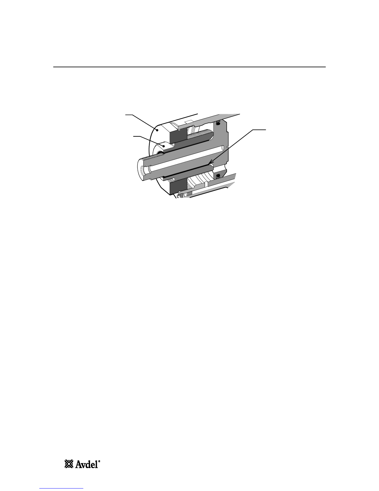
During the pull cycles the piston/collet assembly moves towards the rear of the tool allowing the 0-ring type cushion to
push the follower and jaws forward. If a fastener pin has been inserted in the nose assembly, the jaw set will clamp onto
the pintail and assembly will commence.
For Infalok® the cycle of installation will first clamp the joint to be fastened and then as the anvil continues to move
forward the collar will be swaged into the locking grooves of the pin. At the end of the swaging cycle the anvil will come
up against the joint and as movement continues the pintail will be broken off.
The trigger switch should be released immediately after pin break occurs.
If the trigger is not released, the piston will continue move towards the rear of the tool until it contacts the inner rear face.
When the piston reaches the end of the pull stroke, it uncovers flats on the rear end of a pressure relief valve rod. These
flats are designed to provide a passage for hydraulic fluid between the pull and return side of the piston. Thus allowing
pressurised fluid to be 'unloaded' or 'dumped' back to the reservoir, preventing unnecessary loading to the rear of the tool
body. The placing tool piston will be held in this position until the trigger is released.
Releasing the trigger switch will cause the solenoid to de-energise and reverse the flow of pressurised oil.
However, if during installation the pressure in the pull side achieves a preset 'High Pressure' value set at the pump. At
this point the solenoid valve will automatically de-energise and reverse the flow of pressurised oil to the return side of the
placing tool.
In either case, pressurised oil will now flow into the return side of the placing tool, with the oil in the pull side returning
to the reservoir.
The forward movement of the piston/collet assembly will eject the installed fastener from the anvil.
At the point of releasing the trigger or when the 'High Pressure' value is achieved, the solenoid valve will de-energise and
activate a preset 'Return Timer'. This controls the time that the pump motor will continue run before switching to the idle
mode. The timer can be manually set between 5 and 20 seconds to ensure that the placing tool piston always fully
returns to the forward position (refer to pump manual 07900-01030, pages 10 and 13).
When the piston returns to the fully forward position, the pressure will increase to preset low pressure value - c200bar.
The pump motor will continue to run until the Return Timer has expired. After this time period the motor will stop
automatically and valve will switch to the idle position. The solenoid valve will then automatically cycle to release
pressurised oil to the reservoir from both the pull and return side of the placing tool.
This keeps the installation tool in the forward position. No pressure will be present in the hydraulic system at this point.
The hydraulic pump unit will automatically start up on depression of the tool trigger switch.
nAvder
7
7
Putting Into Service
Principle of Operation
IMPORTANT - READ BOTH THE SAFETY INSTRUCTIONS ON PAGE 3 AND 4 AND THE PUMP UNIT INSTRUCTION
MANUAL CAREFULLY BEFORE PUTTING INTO SERVICE
When both hoses and control cable are connected to the Avdel®/Enerpac®hydraulic pump unit, the pull and return cycles
of the tool are controlled by depressing and releasing the trigger located in the handle.
When the switch is depressed the solenoid valve, located in the hydraulic pump unit, is energised and directs the
pressurised oil flow to the pull side of the piston in the placing tool. This also allows the oil in the return side of the
placing tool to return to the reservoir.
During the pull cycles the piston/collet assembly moves towards the rear of the tool allowing the O-ring type cushion to
push the follower and jaws forward. If a fastener pin has been inserted in the nose assembly, the jaw set will clamp onto
the pintail and assembly will commence.
For Infalok®the cycle of installation will first clamp the joint to be fastened and then as the anvil continues to move
forward the collar will be swaged into the locking grooves of the pin. At the end of the swaging cycle the anvil will come
up against the joint and as movement continues the pintail will be broken off.
The trigger switch should be released immediately after pin break occurs.
If the trigger is not released, the piston will continue move towards the rear of the tool until it contacts the inner rear face.
When the piston reaches the end of the pull stroke, it uncovers flats on the rear end of a pressure relief valve rod. These
flats are designed to provide a passage for hydraulic fluid between the pull and return side of the piston. Thus allowing
pressurised fluid to be ‘unloaded’ or ‘dumped’ back to the reservoir, preventing unnecessary loading to the rear of the tool
body. The placing tool piston will be held in this position until the trigger is released.
Releasing the trigger switch will cause the solenoid to de-energise and reverse the flow of pressurised oil.
However, if during installation the pressure in the pull side achieves a preset ‘High Pressure’ value set at the pump. At
this point the solenoid valve will automatically de-energise and reverse the flow of pressurised oil to the return side of the
placing tool.
In either case, pressurised oil will now flow into the return side of the placing tool, with the oil in the pull side returning
to the reservoir.
The forward movement of the piston/collet assembly will eject the installed fastener from the anvil.
At the point of releasing the trigger or when the ‘High Pressure’ value is achieved, the solenoid valve will de-energise and
activate a preset ‘Return Timer’. This controls the time that the pump motor will continue run before switching to the idle
mode. The timer can be manually set between 5 and 20 seconds to ensure that the placing tool piston always fully
returns to the forward position (refer to pump manual 07900-01030, pages 10 and 13).
When the piston returns to the fully forward position, the pressure will increase to preset low pressure value - c200bar.
The pump motor will continue to run until the Return Timer has expired. After this time period the motor will stop
automatically and valve will switch to the idle position. The solenoid valve will then automatically cycle to release
pressurised oil to the reservoir from both the pull and return side of the placing tool.
This keeps the installation tool in the forward position. No pressure will be present in the hydraulic system at this point.
The hydraulic pump unit will automatically start up on depression of the tool trigger switch.

Putting Into Service
Preparation for Use
CAUTION - CORRECT PULL AND RETURN PRESSURES ARE IMPORTANT FOR PROPER FUNCTION OF THE
ISTALLATION TOOL. PERSONAL INJURY OR DAMAGE TO EQUIPMENT MAY OCCUR WITHOUT CORRECT
PRESSURES. THE PULL AND RETURN PRESSURES SUPPLIED BY THE HYDRAULIC PUMP UNIT MUST NOT
EXCEED THOSE PRESSURES LISTED IN THE PLACING TOOL SPECIFICATION
IMPORTANT — BEFORE PUTTING THE PLACING TOOL AND HYDRAULIC HOSE SET INTO SERVICE:
ENSURE THAT THE PUMP PRESSURE RELIEF VALVES HAVE BEEN SET IN ACCORDANCE WITH THE PUMP
INSTRUCTIONS AND THE MAXIMUM PRESSURES SPECIFIED FOR THE PLACING TOOL AND HOSES.
ENSURE THAT THE HOSE KIT IS PRIMED WITH HYDRAULIC FLUID IN ACCORDANCE WITH THE PROCEDURE IN
THE PUMP INSTRUCTION MANUAL 07900-01030.
•
Ensure the mains power supply to the hydraulic pump unit is switched off.
•
Connect the placing tool hydraulic hose quick couplers directly to the pump unit before connecting the electrical
control cable. Hoses and control cable must be connected in this order and disconnected in reverse order.
•
Switch on the mains supply to the hydraulic pump unit. Wait 5 seconds for the pump unit to complete the boot
sequence, before pressing the trigger switch. When all set the LCD screen on the pump unit will display
'AVDEL'.
•
During the boot sequence the pump control system identifies any trigger operation as a potential malfunction
and prevents the motor from starting. The LCD screen will display 'BUTTON FAULT' in this instance. Reset by
switching off the power supply for 10 seconds.
•
Ensure that the placing tool is positioned below the pump reservoir tanks. Depress the placing tool trigger
switch and allow the tool to achieve full stroke. Continue to depress the trigger to hold the tool in this position
for 30 seconds to circulate hydraulic fluid and expel any air from the tool. Repeat the process three times.
•
Observe action of tool. Check for fluid leaks and ensure that in the idler mode the piston is in the fully forward
position. The placing tool will now be primed.
•
Switch off the mains power supply to the hydraulic pump unit and then disconnect the placing tool from the
pump unit in reverse order to that described above.
•
Now connect the placing tool to the primed hydraulic hose kit and electrical control cable. Then connect
hydraulic hose kit quick couplers and the electrical control cable to the pump unit.
•
Attach the nose assembly to the tool as per the instructions in the relevant nose assembly datasheet.
•
Switch on the mains supply to the hydraulic pump unit as described above.
•
Depress and release the placing tool trigger switch a few times to the full stroke of the tool to circulate hydraulic
fluid.
•
The placing tool is now ready for use.
8
0
Avder
8
Putting Into Service
Preparation for Use
CAUTION - CORRECT PULL AND RETURN PRESSURES ARE IMPORTANT FOR PROPER FUNCTION OF THE
ISTALLATION TOOL. PERSONAL INJURY OR DAMAGE TO EQUIPMENT MAY OCCUR WITHOUT CORRECT
PRESSURES. THE PULL AND RETURN PRESSURES SUPPLIED BY THE HYDRAULIC PUMP UNIT MUST NOT
EXCEED THOSE PRESSURES LISTED IN THE PLACING TOOL SPECIFICATION
IMPORTANT –BEFORE PUTTING THE PLACING TOOL AND HYDRAULIC HOSE SET INTO SERVICE:
ENSURE THAT THE PUMP PRESSURE RELIEF VALVES HAVE BEEN SET IN ACCORDANCE WITH THE PUMP
INSTRUCTIONS AND THE MAXIMUM PRESSURES SPECIFIED FOR THE PLACING TOOL AND HOSES.
ENSURE THAT THE HOSE KIT IS PRIMED WITH HYDRAULIC FLUID IN ACCORDANCE WITH THE PROCEDURE IN
THE PUMP INSTRUCTION MANUAL 07900-01030.
Ensure the mains power supply to the hydraulic pump unit is switched off.
Connect the placing tool hydraulic hose quick couplers directly to the pump unit before connecting the electrical
control cable. Hoses and control cable must be connected in this order and disconnected in reverse order.
Switch on the mains supply to the hydraulic pump unit. Wait 5 seconds for the pump unit to complete the boot
sequence, before pressing the trigger switch. When all set the LCD screen on the pump unit will display
‘AVDEL’.
During the boot sequence the pump control system identifies any trigger operation as a potential malfunction
and prevents the motor from starting. The LCD screen will display ‘BUTTON FAULT’ in this instance. Reset by
switching off the power supply for 10 seconds.
Ensure that the placing tool is positioned below the pump reservoir tanks. Depress the placing tool trigger
switch and allow the tool to achieve full stroke. Continue to depress the trigger to hold the tool in this position
for 30 seconds to circulate hydraulic fluid and expel any air from the tool. Repeat the process three times.
Observe action of tool. Check for fluid leaks and ensure that in the idler mode the piston is in the fully forward
position. The placing tool will now be primed.
Switch off the mains power supply to the hydraulic pump unit and then disconnect the placing tool from the
pump unit in reverse order to that described above.
Now connect the placing tool to the primed hydraulic hose kit and electrical control cable. Then connect
hydraulic hose kit quick couplers and the electrical control cable to the pump unit.
Attach the nose assembly to the tool as per the instructions in the relevant nose assembly datasheet.
Switch on the mains supply to the hydraulic pump unit as described above.
Depress and release the placing tool trigger switch a few times to the full stroke of the tool to circulate hydraulic
fluid.
The placing tool is now ready for use.

Putting Into Service
Operating Instructions
To Install an Infalok® Fastener
•
Check work and remove excessive gap. (Gap is the space between components of the Joint. Gap is excessive if
not enough pintail sticks through the collar for the nose assembly jaws to grab onto).
•
Put Infalok® fastener into hole.
•
Slide Infalok
®
collar over pin. (The beveled end of the collar must be towards the nose assembly and tool.)
•
Push nose assembly onto pin until the nose assembly anvil stops against the collar. Tool and nose assembly
must be held at right angles (90°) to the work.
•
Depress tool trigger switch to start installation cycle.
•
When the forward motion of the nose assembly anvil stops and the pintail breaks off, release the trigger. The
tool will go into its return stroke and push off the installed fastener. At the end of the return stroke the jaws will
release the expended pintail which can be removed by tilting the tool nose down.
•
Once the installed fastener been ejected, the tool and nose assembly is ready for the next installation.
CAUTION - DO NOT ATTEMPT TO BREAK OFF A PINTAIL WITHOUT THE INSTALLATION OF A COLLAR AS THIS
WILL CAUSE THE UNSECURED PORTION OF THE INFALOK® PINTAIL TO EJECT FROM THE NOSE AT A HIGH
SPEED AND FORCE.
nAvder
9
9
Putting Into Service
Operating Instructions
To Install an Infalok® Fastener
Check work and remove excessive gap. (Gap is the space between components of the Joint. Gap is excessive if
not enough pintail sticks through the collar for the nose assembly jaws to grab onto).
Put Infalok®fastener into hole.
Slide Infalok®collar over pin. (The beveled end of the collar must be towards the nose assembly and tool.)
Push nose assembly onto pin until the nose assembly anvil stops against the collar. Tool and nose assembly
must be held at right angles (90°) to the work.
Depress tool trigger switch to start installation cycle.
When the forward motion of the nose assembly anvil stops and the pintail breaks off, release the trigger. The
tool will go into its return stroke and push off the installed fastener. At the end of the return stroke the jaws will
release the expended pintail which can be removed by tilting the tool nose down.
Once the installed fastener been ejected, the tool and nose assembly is ready for the next installation.
CAUTION - DO NOT ATTEMPT TO BREAK OFF A PINTAIL WITHOUT THE INSTALLATION OF A COLLAR AS THIS
WILL CAUSE THE UNSECURED PORTION OF THE INFALOK®PINTAIL TO EJECT FROM THE NOSE AT A HIGH
SPEED AND FORCE.

Servicing the Tool
IMPORTANT - READ SAFETY INSTRUCTIONS ON PAGE 3 AND 4. THE EMPLOYER IS RESPONSIBLE FOR
ENSURING THAT TOOL MAINTENANCE INSTRUCTIONS ARE GIVEN TO THE APPROPRIATE PERSONNEL. THE
OPERATOR SHOULD NOT BE INVOLVED IN MAINTENANCE OR REPAIR OF THE TOOL UNLESS PROPERLY
TRAINED. THE TOOL SHALL BE EXAMINED REGULARLY FOR DAMAGE AND MALFUNCTION.
Daily
•
Check placing tool, hoses and quick couplers for oil leaks.
•
Worn or damaged hoses and couplings should be replaced.
•
Check that the stroke of tool meets the specification.
•
Check that the pump pull / advance pressure relief valve is functioning correctly.
•
Check for worn anvil indicated by score marks on the installed collar. This can also be confirmed by referring to
the installed data in the fastener catalogue. Excessive wear can cause the anvil to rupture.
Weekly
•
Dismantle and clean the nose assembly especially the jaws as described in the relevant nose assembly
datasheet.
•
Check for oil leaks in placing tool, hoses and quick couplers.
Annually or every 150k operations
•
Every 150,000 cycles the tool should be completely dismantled and new components should be used where
worn, damaged or as recommended. All 0-rings, back-up rings and seals should be renewed and lubricated
with MolyKote® 111 grease before assembling.
Service Kit
For a complete service the following Service Kit is available:
SERVICE KIT: 73435-99990
PART NUMBER
07005-10118
DESCRIPTION
Quick Coupler - Male
PART NUMBER
07900-00997
DESCRIPTION
AV50 Piston Extraction Rod
07005-10120
Quick Coupler - Female
07900-00998
AV50 Piston Extraction Sleeve
07900-00974
AV50 Piston Seal Sleeve
07900-01024
AV50 Seal Gland Removal Tool
07900-00975
AV50 Piston Seal Plunger
07001-00596
M5 x 35 Skt Cap Head Screws
07900-00976
AV50 Piston Extractor
07992-00020
Grease — MolyLithium EP3753
07900-00977
AV50 Piston Bullet - Front
07900-00755
Grease — Molykote
®
111
07900-00980
AV50 Ejector Cap Tool
07900-00756
Loctite
®
243 Threadlocker
The following standard tools are also required:
•
Allen Key: 2.0 / 2.5 / 3.0 mm
•
Open End Flat Spanner: 12 / 14 / 18 / 24 / 55 mm NF
•
PTFE Tape: 10 mm
•
Engineers Vice with Jaw Guards — 150 mm
10 >2
Avde1•
10
Servicing the Tool
IMPORTANT - READ SAFETY INSTRUCTIONS ON PAGE 3 AND 4. THE EMPLOYER IS RESPONSIBLE FOR
ENSURING THAT TOOL MAINTENANCE INSTRUCTIONS ARE GIVEN TO THE APPROPRIATE PERSONNEL. THE
OPERATOR SHOULD NOT BE INVOLVED IN MAINTENANCE OR REPAIR OF THE TOOL UNLESS PROPERLY
TRAINED. THE TOOL SHALL BE EXAMINED REGULARLY FOR DAMAGE AND MALFUNCTION.
Daily
Check placing tool, hoses and quick couplers for oil leaks.
Worn or damaged hoses and couplings should be replaced.
Check that the stroke of tool meets the specification.
Check that the pump pull / advance pressure relief valve is functioning correctly.
Check for worn anvil indicated by score marks on the installed collar. This can also be confirmed by referring to
the installed data in the fastener catalogue. Excessive wear can cause the anvil to rupture.
Weekly
Dismantle and clean the nose assembly especially the jaws as described in the relevant nose assembly
datasheet.
Check for oil leaks in placing tool, hoses and quick couplers.
Annually or every 150k operations
Every 150,000 cycles the tool should be completely dismantled and new components should be used where
worn, damaged or as recommended. All O-rings, back-up rings and seals should be renewed and lubricated
with MolyKote®111 grease before assembling.
Service Kit
For a complete service the following Service Kit is available:
SERVICE KIT: 73435-99990
PART NUMBER
DESCRIPTION
PART NUMBER
DESCRIPTION
07005-10118
Quick Coupler - Male
07900-00997
AV50 Piston Extraction Rod
07005-10120
Quick Coupler - Female
07900-00998
AV50 Piston Extraction Sleeve
07900-00974
AV50 Piston Seal Sleeve
07900-01024
AV50 Seal Gland Removal Tool
07900-00975
AV50 Piston Seal Plunger
07001-00596
M5 x 35 Skt Cap Head Screws
07900-00976
AV50 Piston Extractor
07992-00020
Grease –MolyLithium EP3753
07900-00977
AV50 Piston Bullet - Front
07900-00755
Grease –Molykote®111
07900-00980
AV50 Ejector Cap Tool
07900-00756
Loctite®243 Threadlocker
The following standard tools are also required:
Allen Key: 2.0 / 2.5 / 3.0 mm
Open End Flat Spanner: 12 / 14 / 18 / 24 / 55 mm A/F
PTFE Tape: 10 mm
Engineers Vice with Jaw Guards –150 mm

Servicing the Tool
Use only Enerpac
®
HF hydraulic oil — the use of any other oil may cause the placing tool and pump to malfunction and
will render the placing tool warranty null and void. Hydraulic oil is available to order under the following part numbers.
HYDRAULIC OIL
PART NUMBER
Enerpac® Part Number
07992-00081
HF-95X
07992-00082
HF-95Y
07992-00083
HF-95T
Volume
1 Litre
5 Litres
20 Litres
Viscosity
32 mm
2
/s
32 mm
2
/s
32 mm
2
/s
Dismantling Instructions
IMPORTANT — ENSURE THE MAINS POWER SUPPLY TO THE HYDRAULIC PUMP UNIT IS SWITCHED OFF
BEFORE REMOVING THE NOSE ASSEMBLY OR DISMANTLING THE PLACING TOOL.
Before Dismantling:
•
Uncouple the Quick Couplers
10
and
11
and the electrical Control Cable
14
between the placing tool and the
Hydraulic Hose Assembly.
•
Remove the nose assembly from the placing tool as per the instructions in the nose assembly datasheet.
For a complete service of the tool, we advise that you proceed with dismantling the tool in the order shown on pages 11
to 14. After dismantling the tool we recommend that you replace all seals.
All numbers in bold refer to the General Assembly and Parts List on pages 15, 16 and 17.
Head Piston Assembly:
•
Using a small flat screwdriver, remove the Pin
41
from the Collet Adapter
40.
•
Unscrew and remove the Collet Adapter
40
from the Piston
1.
•
Clamp the tool body in a vice with soft jaws so that the tool is pointing nose up.
•
Using a 2.5mm Allen Key, unscrew and remove Set Screw
28.
•
Connect the spare *Quick Coupler - Female to the Quick Coupler — Male
10
on the Hydraulic Hose - Pull
19.
This will release pressure from the pull side of the Piston and ease the removal of the Seal Gland
17.
•
Insert the *Seal Gland Removal Tool into the front of the Nose Cap
15
and attach to the Seal Gland
17
using
the three *M5 x 35 Skt Cap Head Screws.
•
Using a large adjustable spanner or clamp, fully unscrew Nose Cap
15,
from the Body
2.
In doing so the Seal
Gland
17
will be drawn out of the Body. Reasonable force will be required. Once the Nose Cap is unscrewed
the complete assembly can be pulled off of the Piston
1
and removed from the Body.
•
Unscrew the three *M5 x 35 Skt Cap Head Screws and remove the *Seal Gland Removal Tool from the Nose
Cap
15
and Seal Gland
17.
The two parts can now be separated.
•
Using a small flat screwdriver, remove 0-Rings
21
and
33
from the Nose Cap
15
and discard.
•
Using a small flat screwdriver or similar tool, remove 0-Ring
23
and Anti-Extrusion Ring
27,
from the external
groove on the Seal Gland
17,
and discard. When removing the seals, take care not to damage the surface of the
Seal Gland with the screwdriver.
All numbers in
bold
refer to the General Assembly and Parts List on pages 16, 17 and 18.
* Service Kit on page 10
Avdel•
11
11
Servicing the Tool
Use only Enerpac®HF hydraulic oil –the use of any other oil may cause the placing tool and pump to malfunction and
will render the placing tool warranty null and void. Hydraulic oil is available to order under the following part numbers.
HYDRAULIC OIL
PART NUMBER
07992-00081
07992-00082
07992-00083
Enerpac®Part Number
HF-95X
HF-95Y
HF-95T
Volume
1 Litre
5 Litres
20 Litres
Viscosity
32 mm2/s
32 mm2/s
32 mm2/s
Dismantling Instructions
IMPORTANT –ENSURE THE MAINS POWER SUPPLY TO THE HYDRAULIC PUMP UNIT IS SWITCHED OFF
BEFORE REMOVING THE NOSE ASSEMBLY OR DISMANTLING THE PLACING TOOL.
Before Dismantling:
Uncouple the Quick Couplers 10 and 11 and the electrical Control Cable 14 between the placing tool and the
Hydraulic Hose Assembly.
Remove the nose assembly from the placing tool as per the instructions in the nose assembly datasheet.
For a complete service of the tool, we advise that you proceed with dismantling the tool in the order shown on pages 11
to 14. After dismantling the tool we recommend that you replace all seals.
All numbers in bold refer to the General Assembly and Parts List on pages 15, 16 and 17.
Head Piston Assembly:
Using a small flat screwdriver, remove the Pin 41 from the Collet Adapter 40.
Unscrew and remove the Collet Adapter 40 from the Piston 1.
Clamp the tool body in a vice with soft jaws so that the tool is pointing nose up.
Using a 2.5mm Allen Key, unscrew and remove Set Screw 28.
Connect the spare *Quick Coupler - Female to the Quick Coupler –Male 10 on the Hydraulic Hose - Pull 19.
This will release pressure from the pull side of the Piston and ease the removal of the Seal Gland 17.
Insert the *Seal Gland Removal Tool into the front of the Nose Cap 15 and attach to the Seal Gland 17 using
the three *M5 x 35 Skt Cap Head Screws.
Using a large adjustable spanner or clamp, fully unscrew Nose Cap 15, from the Body 2. In doing so the Seal
Gland 17 will be drawn out of the Body. Reasonable force will be required. Once the Nose Cap is unscrewed
the complete assembly can be pulled off of the Piston 1 and removed from the Body.
Unscrew the three *M5 x 35 Skt Cap Head Screws and remove the *Seal Gland Removal Tool from the Nose
Cap 15 and Seal Gland 17. The two parts can now be separated.
Using a small flat screwdriver, remove O-Rings 21 and 33 from the Nose Cap 15 and discard.
Using a small flat screwdriver or similar tool, remove O-Ring 23 and Anti-Extrusion Ring 27, from the external
groove on the Seal Gland 17, and discard. When removing the seals, take care not to damage the surface of the
Seal Gland with the screwdriver.
All numbers in bold refer to the General Assembly and Parts List on pages 16, 17 and 18.
*Service Kit on page 10

Servicing the Tool
•
Remove Rod Seal
25
and Wiper Seal
22,
from the internal grooves on the Seal Gland
17,
and discard. When
removing the seals, take care not to damage the surface of the Front Seal Gland with the screwdriver.
•
Remove the Front Bearing Ring
24
and check the part for wear or damage. Discard if necessary.
•
Remove the placing tool from the vice and empty the hydraulic oil from the front of the tool and then re-clamp
the tool in the vice as before. Remove the spare *Quick Coupler — Female from the Quick Coupler - Male
10.
•
Connect the spare *Quick Coupler - Male to the Quick Coupler - Female
11
on the Hydraulic Hose — Return
18.
This will release any pressure from the return side of the Piston
1
and ease the removal of the Piston.
•
Place the *Piston Extraction Sleeve inside the bore of the *Piston Extraction Rod and then screw the assembly
into the centre of the *Piston Extractor.
•
Place the complete *Piston Extractor Tool assembly over the shaft of Piston
2
and screw the *Piston Extractor
fully into the font of the Body
2.
Screw the *Piston Extraction Rod into the *Piston Extractor until it stops
against the front face of the Piston. Screw the Collet Adapter
40
on to the Piston
1
until the front face is flush
with the end of the Piston. Align the hole in the Collet Adapter with the slot in the end of the Piston and then
insert Locking Pin
41.
Refer to the illustration below for the correct assembly of the *Piston Extraction Tools.
Piston Extractor
Piston Extraction
Rod
Piston Extraction
Sleeve
•
Using a 55 mm spanner, unscrew the *Piston Extraction Rod from the *Piston Extractor - this will slowly pull
the Piston
1
from the bore of the Body
2.
Continue to unscrew the *Piston Extraction Rod until the Piston is
pulled to stop against the front face of the *Piston Extractor. Lift and remove the *Piston Extraction Tools
together with the Piston from the front of the Body.
•
Remove the Pin
41
and Collet Adapter
40
from the Piston
1,
enabling the Piston to be removed from the Piston
Extraction Tools.
•
Remove the Valve Rod
16
from the Piston
1
and check the part for wear or damage. Replace if necessary.
•
Remove the placing tool from the vice and empty the hydraulic oil from the tool. Remove the spare *Quick
Coupler — Male from the Quick Coupler - Female
11.
•
The Piston Seal
26
is a 2-piece seal consisting of an external sealing ring and an inner o-ring. Using a small
knife, cut through the external sealing ring and remove from the external groove on the Piston
1.
Then using a
small flat screwdriver remove the inner o-ring from the Piston, and discard. When removing the seals, take care
not to damage the surface of the Piston.
•
Do not remove Set Screw
42
from the Body
2.
All numbers in
bold
refer to the General Assembly and Parts List on pages 16, 17 and 18.
* Service Kit on page 10
12
>2
Avde1•
12
Servicing the Tool
Remove Rod Seal 25 and Wiper Seal 22, from the internal grooves on the Seal Gland 17, and discard. When
removing the seals, take care not to damage the surface of the Front Seal Gland with the screwdriver.
Remove the Front Bearing Ring 24 and check the part for wear or damage. Discard if necessary.
Remove the placing tool from the vice and empty the hydraulic oil from the front of the tool and then re-clamp
the tool in the vice as before. Remove the spare *Quick Coupler –Female from the Quick Coupler - Male 10.
Connect the spare *Quick Coupler - Male to the Quick Coupler - Female 11 on the Hydraulic Hose –Return 18.
This will release any pressure from the return side of the Piston 1and ease the removal of the Piston.
Place the *Piston Extraction Sleeve inside the bore of the *Piston Extraction Rod and then screw the assembly
into the centre of the *Piston Extractor.
Place the complete *Piston Extractor Tool assembly over the shaft of Piston 2and screw the *Piston Extractor
fully into the font of the Body 2. Screw the *Piston Extraction Rod into the *Piston Extractor until it stops
against the front face of the Piston. Screw the Collet Adapter 40 on to the Piston 1until the front face is flush
with the end of the Piston. Align the hole in the Collet Adapter with the slot in the end of the Piston and then
insert Locking Pin 41. Refer to the illustration below for the correct assembly of the *Piston Extraction Tools.
Using a 55 mm spanner, unscrew the *Piston Extraction Rod from the *Piston Extractor - this will slowly pull
the Piston 1 from the bore of the Body 2. Continue to unscrew the *Piston Extraction Rod until the Piston is
pulled to stop against the front face of the *Piston Extractor. Lift and remove the *Piston Extraction Tools
together with the Piston from the front of the Body.
Remove the Pin 41 and Collet Adapter 40 from the Piston 1, enabling the Piston to be removed from the Piston
Extraction Tools.
Remove the Valve Rod 16 from the Piston 1 and check the part for wear or damage. Replace if necessary.
Remove the placing tool from the vice and empty the hydraulic oil from the tool. Remove the spare *Quick
Coupler –Male from the Quick Coupler - Female 11.
The Piston Seal 26 is a 2-piece seal consisting of an external sealing ring and an inner o-ring. Using a small
knife, cut through the external sealing ring and remove from the external groove on the Piston 1. Then using a
small flat screwdriver remove the inner o-ring from the Piston, and discard. When removing the seals, take care
not to damage the surface of the Piston.
Do not remove Set Screw 42 from the Body 2.
All numbers in bold refer to the General Assembly and Parts List on pages 16, 17 and 18.
*Service Kit on page 10
Piston Extractor
Piston Extraction
Rod
Piston Extraction
Sleeve

Servicing the Tool
Assemble in reverse order to dismantling noting the following points:
•
Clean all components before assembling.
•
To aid assembly of seals apply a light coating of Molykote
®
111 grease to all seals, seal grooves, back-up rings
and the assembly tools.
•
Lubricate the seal groove and major external diameter of the Piston
1
with Molykote
®
111 grease. Slide the
inner o-ring from Piston Seal
26
over the front of the major Piston diameter and into the seal groove.
•
Screw the *Piston Bullet on to the Piston
1.
Place the *Piston Seal Sleeve over the Piston shaft and then place
the outer sealing ring from Piston Seal
26
over the *Piston Seal Sleeve so that it rests on the tapered diameter.
Lubricate the surface of the *Piston Seal Sleeve with Molykote
®
111 grease.
•
Place the *Piston Seal Plunger over the Piston
1
shaft and the *Piston Seal Sleeve so that the open end of the
*Piston Seal Plunger rests on the outer sealing ring of Piston Seal
26.
Using the *Piston Seal Plunger, push the
outer sealing ring over the *Piston Seal Sleeve and into the Piston seal groove. Reasonable force is required to
expand and insert the outer sealing ring on the Piston, so the use of a press or vice is necessary.
•
Remove the *Piston Seal Plunger and the *Piston Seal Sleeve from the Piston
1.
Lubricate the *Piston Bullet -
Front, Piston shaft and Piston Seal
26
with Molykote
®
111 grease.
•
Clamp the tool body in a vice with soft jaws so that the tool is pointing nose up.
•
Fill the rear of the Body
2
with Enerpac® HF hydraulic oil to a depth of approximately 30 mm.
•
Apply a light coating of Molykote
®
111 grease to leading edges and bore within the Body
2
and to the Piston
Seal
26.
•
Place the Piston
1
in the front of the Body
2,
so that the rear edge of Piston Seal
26
rests on the leading edge
of the main bore within the Body. When inserting the Piston the take care not to damage the Piston Seal on the
threads at the front end of the Body.
•
Place the *Piston Extraction Sleeve inside the bore of the *Piston Extraction Rod and then screw the assembly
into the centre of the *Piston Extractor. Place the assembled *Piston Extractor Tool over the shaft of Piston
1
and screw the *Piston Extractor fully into the font of the Body
2.
Refer to the illustration below for the correct
assembly of the *Piston Extraction Tools.
Piston Extractor
Piston Extraction
Rod
Piston Extraction
Sleeve
All numbers in
bold
refer to the General Assembly and Parts List on pages 16, 17 and 18.
* Service Kit on page 10
nAvder
13
13
Servicing the Tool
Assemble in reverse order to dismantling noting the following points:
Clean all components before assembling.
To aid assembly of seals apply a light coating of Molykote®111 grease to all seals, seal grooves, back-up rings
and the assembly tools.
Lubricate the seal groove and major external diameter of the Piston 1with Molykote®111 grease. Slide the
inner o-ring from Piston Seal 26 over the front of the major Piston diameter and into the seal groove.
Screw the *Piston Bullet on to the Piston 1. Place the *Piston Seal Sleeve over the Piston shaft and then place
the outer sealing ring from Piston Seal 26 over the *Piston Seal Sleeve so that it rests on the tapered diameter.
Lubricate the surface of the *Piston Seal Sleeve with Molykote®111 grease.
Place the *Piston Seal Plunger over the Piston 1shaft and the *Piston Seal Sleeve so that the open end of the
*Piston Seal Plunger rests on the outer sealing ring of Piston Seal 26. Using the *Piston Seal Plunger, push the
outer sealing ring over the *Piston Seal Sleeve and into the Piston seal groove. Reasonable force is required to
expand and insert the outer sealing ring on the Piston, so the use of a press or vice is necessary.
Remove the *Piston Seal Plunger and the *Piston Seal Sleeve from the Piston 1. Lubricate the *Piston Bullet -
Front, Piston shaft and Piston Seal 26 with Molykote®111 grease.
Clamp the tool body in a vice with soft jaws so that the tool is pointing nose up.
Fill the rear of the Body 2with Enerpac®HF hydraulic oil to a depth of approximately 30 mm.
Apply a light coating of Molykote®111 grease to leading edges and bore within the Body 2and to the Piston
Seal 26.
Place the Piston 1 in the front of the Body 2, so that the rear edge of Piston Seal 26 rests on the leading edge
of the main bore within the Body. When inserting the Piston the take care not to damage the Piston Seal on the
threads at the front end of the Body.
Place the *Piston Extraction Sleeve inside the bore of the *Piston Extraction Rod and then screw the assembly
into the centre of the *Piston Extractor. Place the assembled *Piston Extractor Tool over the shaft of Piston 1
and screw the *Piston Extractor fully into the font of the Body 2. Refer to the illustration below for the correct
assembly of the *Piston Extraction Tools.
All numbers in bold refer to the General Assembly and Parts List on pages 16, 17 and 18.
*Service Kit on page 10
Piston Extractor
Piston Extraction
Rod
Piston Extraction
Sleeve

Servicing the Tool
•
Using a 55mm spanner screw the *Piston Extraction Rod into the *Piston Extractor until it contacts and presses
the Piston
1
into the Body
2.
Continue to screw the *Piston Extraction Rod clockwise until only 10mm of the
Piston Extraction Rod is protruding from the front face of the Piston Extractor. The Piston will now be inserted
into the main bore of the Body
2.
Refer to the illustration below.
Piston Extractor
Piston Extraction
Piston Extraction
Sleeve
Rod
•
Manually push the end of the Piston
1
fully into the Body
2
until it stops against the rear of the bore. Remove
the *Piston Extractor, *Piston Extraction Rod and *Piston Seal Sleeve from the Piston and Body.
•
Fill the front of the Body
2
with Enerpac
®
HF hydraulic oil. Oil level should be just above the front inlet bore
into the Body.
•
Insert the Valve Rod
16
into the Piston
2,
with the end with the machined flats first.
•
Slide 0-Ring
23
over the Seal Gland
17
and into the external groove. Insert the Anti-Extrusion Ring
27
in the
same groove, in front of the installed 0-Ring. Refer to the General Assembly and Parts List for the correct
orientation of the 0-Ring and Anti-Extrusion Ring.
•
Press the Front Bearing Ring
24
into the internal recess within the Seal Gland
17
and then install Rod Seal
25
behind the Front Bearing Ring. Install the Wiper Seal
22
in the front recess of the Seal Gland. Refer to the
General Assembly to ensure the correct orientation of the Rod Seal and Wiper Seal.
•
Lubricate the surface and leading edge of the Body
2
bore into which the Seal Gland
17
is to be installed with
Molykote
®
111 grease.
•
Connect the spare *Quick Coupler - Female to the Quick Coupler - Male
10
on the Hydraulic Hose — Pull
19.
This will allow air to be released from the pull side Piston
1
when inserting the Seal Gland
17.
•
Insert the Seal Gland
17
over the Piston
1
and push into the Front of the Body
2
until the internal threads in
the front of the Body are exposed. Take care not to damage the 0-Ring
23
and Anti-Extrusion Ring
27
on the
Body threads.
•
Lubricate both the internal thread in the Body
2
and the external thread on Nose Cap
15
with MolyLithium
Grease.
•
Insert the Nose Cap
15
into the front of the Body
2.
Screw the Nose Cap
15
fully into the Body using a large
adjustable spanner or clamp. In doing so, this will install the Seal Gland
17
into the correct position within the
Body. A small amount of oil will be expelled from the Hydraulic Hose — Pull
19.
•
Remove spare *Quick Coupler - Female from the Quick Coupler - Male
10
on the Hydraulic Hose — Pull
19.
All numbers in
bold
refer to the General Assembly and Parts List on pages 16, 17 and 18.
* Service Kit on page 10
14
>2
Avdels
14
Servicing the Tool
Using a 55mm spanner screw the *Piston Extraction Rod into the *Piston Extractor until it contacts and presses
the Piston 1into the Body 2. Continue to screw the *Piston Extraction Rod clockwise until only 10mm of the
Piston Extraction Rod is protruding from the front face of the Piston Extractor. The Piston will now be inserted
into the main bore of the Body 2. Refer to the illustration below.
Manually push the end of the Piston 1fully into the Body 2 until it stops against the rear of the bore. Remove
the *Piston Extractor, *Piston Extraction Rod and *Piston Seal Sleeve from the Piston and Body.
Fill the front of the Body 2with Enerpac®HF hydraulic oil. Oil level should be just above the front inlet bore
into the Body.
Insert the Valve Rod 16 into the Piston 2, with the end with the machined flats first.
Slide O-Ring 23 over the Seal Gland 17 and into the external groove. Insert the Anti-Extrusion Ring 27 in the
same groove, in front of the installed O-Ring. Refer to the General Assembly and Parts List for the correct
orientation of the O-Ring and Anti-Extrusion Ring.
Press the Front Bearing Ring 24 into the internal recess within the Seal Gland 17 and then install Rod Seal 25
behind the Front Bearing Ring. Install the Wiper Seal 22 in the front recess of the Seal Gland. Refer to the
General Assembly to ensure the correct orientation of the Rod Seal and Wiper Seal.
Lubricate the surface and leading edge of the Body 2bore into which the Seal Gland 17 is to be installed with
Molykote®111 grease.
Connect the spare *Quick Coupler - Female to the Quick Coupler - Male 10 on the Hydraulic Hose –Pull 19.
This will allow air to be released from the pull side Piston 1when inserting the Seal Gland 17.
Insert the Seal Gland 17 over the Piston 1 and push into the Front of the Body 2until the internal threads in
the front of the Body are exposed. Take care not to damage the O-Ring 23 and Anti-Extrusion Ring 27 on the
Body threads.
Lubricate both the internal thread in the Body 2and the external thread on Nose Cap 15 with MolyLithium
Grease.
Insert the Nose Cap 15 into the front of the Body 2. Screw the Nose Cap 15 fully into the Body using a large
adjustable spanner or clamp. In doing so, this will install the Seal Gland 17 into the correct position within the
Body. A small amount of oil will be expelled from the Hydraulic Hose –Pull 19.
Remove spare *Quick Coupler - Female from the Quick Coupler - Male 10 on the Hydraulic Hose –Pull 19.
All numbers in bold refer to the General Assembly and Parts List on pages 16, 17 and 18.
*Service Kit on page 10
Piston Extractor
Piston Extraction
Rod
Piston Extraction
Sleeve

Servicing the Tool
•
Screw the Collet Adapter
40
on to the Piston
1
until the front face is flush with the end of the Piston. Align the
hole in the Collet Adapter with the slot in the end of the Piston and then insert Locking Pin
41.
•
Prime the placing tool as described in Preparation for Use on page 8.
Hose Assembly:
•
Remove the two Screws
9
from the Hose Clamp
13
using a 3.0mm Allen Key. Remove the Hose Clamp and
Clamp Insert
20
from the Protective Sleeve
37
and Hydraulic Hoses
18
and
19.
•
Using the small flat screwdriver prize the Handle Gator
8
from the handle of Body
2.
Pull the Handle Gator over
the Protective Sleeve
37,
Hydraulic Hoses
18
and
19
and remove.
•
Cut the Cable Tie
35
and slide back the Protective Sleeve
37
to expose the fittings on the Hydraulic Hoses
18
and
19.
The Hydraulic Hoses can be removed form the Body
2
using 12mm and 14mm spanners.
•
The Quick Couplers
10
and
11
can be removed from the Hydraulic Hoses
18
and
19
using 18mm and 24mm
spanners.
•
To remove Trigger Switch
7,
first loosen Cable Gland
38,
so that the Control Cable
14
is free to move within the
Body
2.
Then undo M4 Set Screw
12
using a 2.0mm Allen Key.
•
Push the Control Cable
14
into the Body
2
and simultaneously pull the Trigger Switch
7
out of the Body to
expose the solder joints on the Trigger Switch terminals. Unsolder the terminals to remove the Trigger Switch
and Trigger Insert
39.
The Trigger Insert is bonded to the Trigger Switch and cannot be removed.
•
The Control Cable
14
can now be pulled from the Body
2
and removed from the Protective Sleeve
37.
Assemble in reverse order to dismantling noting the following points:
•
Prior to assembly clean all threads on the Quick Couplers - Male
10
and Female
11
and the Hydraulic Hoses —
Return
18
and Pull
19.
Apply 2 to 3 layers of 10mm PTFE tape to the male threads of both Hydraulic Hoses.
•
When replacing the Trigger Switch
7
apply Loctite
®
243 to the male thread on the Trigger Switch before
assembling the Trigger Insert
39.
•
Apply Loctite
®
243 to M4 Set Screw
12
prior to assembly.
•
Once assembled, prime the tool as per the instructions on page 8.
All numbers in
bold
refer to the General Assembly and Parts List on pages 16, 17 and 18.
* Service Kit on page 10
Avdel•
15
15
Servicing the Tool
Screw the Collet Adapter 40 on to the Piston 1until the front face is flush with the end of the Piston. Align the
hole in the Collet Adapter with the slot in the end of the Piston and then insert Locking Pin 41.
Prime the placing tool as described in Preparation for Use on page 8.
Hose Assembly:
Remove the two Screws 9from the Hose Clamp 13 using a 3.0mm Allen Key. Remove the Hose Clamp and
Clamp Insert 20 from the Protective Sleeve 37 and Hydraulic Hoses 18 and 19.
Using the small flat screwdriver prize the Handle Gator 8from the handle of Body 2. Pull the Handle Gator over
the Protective Sleeve 37, Hydraulic Hoses 18 and 19 and remove.
Cut the Cable Tie 35 and slide back the Protective Sleeve 37 to expose the fittings on the Hydraulic Hoses 18
and 19. The Hydraulic Hoses can be removed form the Body 2using 12mm and 14mm spanners.
The Quick Couplers 10 and 11 can be removed from the Hydraulic Hoses 18 and 19 using 18mm and 24mm
spanners.
To remove Trigger Switch 7, first loosen Cable Gland 38, so that the Control Cable 14 is free to move within the
Body 2. Then undo M4 Set Screw 12 using a 2.0mm Allen Key.
Push the Control Cable 14 into the Body 2and simultaneously pull the Trigger Switch 7out of the Body to
expose the solder joints on the Trigger Switch terminals. Unsolder the terminals to remove the Trigger Switch
and Trigger Insert 39. The Trigger Insert is bonded to the Trigger Switch and cannot be removed.
The Control Cable 14 can now be pulled from the Body 2and removed from the Protective Sleeve 37.
Assemble in reverse order to dismantling noting the following points:
Prior to assembly clean all threads on the Quick Couplers - Male 10 and Female 11 and the Hydraulic Hoses –
Return 18 and Pull 19. Apply 2 to 3 layers of 10mm PTFE tape to the male threads of both Hydraulic Hoses.
When replacing the Trigger Switch 7apply Loctite®243 to the male thread on the Trigger Switch before
assembling the Trigger Insert 39.
Apply Loctite®243 to M4 Set Screw 12 prior to assembly.
Once assembled, prime the tool as per the instructions on page 8.
All numbers in bold refer to the General Assembly and Parts List on pages 16, 17 and 18.
*Service Kit on page 10

2
5
15
40
10
11
4
8
13
14
General Assembly of Installation Tool 73435-02000
ITEM 37 PROTECTIVE SLEEVE
REMOVED FOR CLARITY
REMOVED FOR CLARITY
16
>X
Avde1®
16
General Assembly of Installation Tool 73435-02000

29
30
17
31
16
21 33 27 23 26
=2=a4=1OtttlatlAWAM
41 40
42
18
DETAIL C
19
39
22 24 25
DETAIL B
SECTION A-A
Avdel®
17
20
DETAIL D
DETAIL E
General Assembly of Installation Tool 73435-02000
17
General Assembly of Installation Tool 73435-02000

Parts List for Installation Tool 73435-02000
ITEM
1
PART NUMBER
73435-02003
73435-02000 Parts List
DESCRIPTION
PISTON
QTY.
1
2
73435-02001
BODY
1
3
4
73430-02025
SAFETY LABEL
1
5
73435-02026
AV50 LABEL
2
6
7
07007-02103
TRIGGER SWITCH
1
8
73430-02020
HANDLE GATOR
1
9
07001-00686
M4 X 16 SKT CAP HD SCREW
2
10
07005-10118
QUICK COUPLER - MALE
1
11
07005-10120
QUICK COUPLER - FEMALE
1
12
07001-00479
M4 X 4 SKT SET SCREW
1
13
73430-02023
HOSE CLAMP
1
14
07007-02105
CONTROL CABLE
1
15
73435-02004
NOSE CAP
1
16
73435-02005
VALVE ROD
1
17
73435-02010
SEAL GLAND
1
18
07005-10119
HYDRAULIC HOSE - RETURN
1
19
07005-10117
HYDRAULIC HOSE - PULL
1
20
73430-02024
CLAMP INSERT
1
21
07003-00465
0-RING
1
22
07003-00455
WIPER SEAL
1
23
07003-00498
0-RING
1
24
73435-02009
FRONT BEARING RING
1
25
07003-00454
ROD SEAL
1
26
07003-00456
PISTON SEAL
1
27
73435-02014
ANTI-EXTRUSION RING
1
28
07001-00692
M5 X 8 SKT SET SCREW
1
29
73435-02006
EJECTOR PIN
1
30
73435-02007
EJECTOR CAP
1
31
73435-02008
SPRING
1
32
33
07003-00466
0-RING
1
34
35
07007-02032
CABLE TIE
1
36
1
37
07005-10121
PROTECTIVE SLEEVE
0.6m
38
07007-02104
CABLE GLAND
1
39
73430-02008
TRIGGER INSERT
1
40
73435-02012
COLLET ADAPTER
1
41
73435-02013
LOCKING PIN
1
42
07001-00689
M8 X 8 SKT SET SCREW
1
-
07900-01023
AV50 TOOL INSTRUCTION MANUAL
1
18
>X
Avde1®
18
Parts List for Installation Tool 73435-02000
73435-02000 Parts List
ITEM
PART NUMBER
DESCRIPTION
QTY.
1
73435-02003
PISTON
1
2
73435-02001
BODY
1
3
4
73430-02025
SAFETY LABEL
1
5
73435-02026
AV50 LABEL
2
6
7
07007-02103
TRIGGER SWITCH
1
8
73430-02020
HANDLE GATOR
1
9
07001-00686
M4 X 16 SKT CAP HD SCREW
2
10
07005-10118
QUICK COUPLER - MALE
1
11
07005-10120
QUICK COUPLER - FEMALE
1
12
07001-00479
M4 X 4 SKT SET SCREW
1
13
73430-02023
HOSE CLAMP
1
14
07007-02105
CONTROL CABLE
1
15
73435-02004
NOSE CAP
1
16
73435-02005
VALVE ROD
1
17
73435-02010
SEAL GLAND
1
18
07005-10119
HYDRAULIC HOSE - RETURN
1
19
07005-10117
HYDRAULIC HOSE - PULL
1
20
73430-02024
CLAMP INSERT
1
21
07003-00465
O-RING
1
22
07003-00455
WIPER SEAL
1
23
07003-00498
O-RING
1
24
73435-02009
FRONT BEARING RING
1
25
07003-00454
ROD SEAL
1
26
07003-00456
PISTON SEAL
1
27
73435-02014
ANTI-EXTRUSION RING
1
28
07001-00692
M5 X 8 SKT SET SCREW
1
29
73435-02006
EJECTOR PIN
1
30
73435-02007
EJECTOR CAP
1
31
73435-02008
SPRING
1
32
33
07003-00466
O-RING
1
34
35
07007-02032
CABLE TIE
1
36
1
37
07005-10121
PROTECTIVE SLEEVE
0.6m
38
07007-02104
CABLE GLAND
1
39
73430-02008
TRIGGER INSERT
1
40
73435-02012
COLLET ADAPTER
1
41
73435-02013
LOCKING PIN
1
42
07001-00689
M8 X 8 SKT SET SCREW
1
-
07900-01023
AV50 TOOL INSTRUCTION MANUAL
1

Safety Data
Enerpac
®
HF Hydraulic Oil - Safety Data
FIRST AID
SKIN:
Unlikely to cause harm to the skin on brief or occasional contact but prolonged or exposure may lead to dermatitis. Wash
skin thoroughly with soap and water as soon as reasonably practicable. Remove heavily contaminated clothing and wash
underlying skin.
ORAL:
Unlikely to cause harm if accidentally swallowed in small doses, though larger quantities may cause nausea and
diarrhea. If contamination of the mouth occurs, wash out thoroughly with water. Except as a deliberate act, the ingestion
of large amounts of product is unlikely. If it should occur, do not induce vomiting; obtain medical advice. Take person to
nearest medical centre.
EYES:
Unlikely to cause more than transient stinging or redness if accidental eye contact occurs. Wash eyes thoroughly with
copious quantities of water, ensuring eyelids are held open. Obtain medical advice if any pain or redness develops or
persists.
MEDICAL
ADVICE:
Treatment should in general be symptomatic and directed to relieving any effects.
Note:
High Pressure Applications:
Injections through the skin, resulting from contact with the product at high pressure, constitute a major medical
emergency. Injuries may not appear serious at first but within a few hours tissue becomes swollen, discoloured and
extremely painful with extensive subcutaneous necrosis.
Surgical exploration should be undertaken without delay. Thorough and extensive debridement of the wound and
underlying tissue is necessary to minimize tissue loss and prevent or limit permanent damage. Note that high pressure
may force the product considerable distances along tissue planes.
DISPOSAL
Remove all spills with inert absorbent material. Ventilate spill area. Place contaminated materials in a disposable
container and dispose in a manner consistent with local regulations.
FIRE
FLASH POINT:
200°C.
Extinguish with either dry chemical, foam or carbon dioxide. Do not enter confined space without self contained breathing
apparatus.
HANDLING
Use barrier cream or oil resistant gloves.
STORAGE
Undercover and consistent with local regulations for inflammable material.
MolyLithium Grease EP 3753 - Safety Data
Grease can be ordered as a single item, the part number is shown in the Service Kit page 10.
FIRST AID
SKIN:
As the grease is completely water resistant it is best removed with an approved emulsifying skin cleaner.
INGESTION:
Ensure the individual drinks 30m1 Milk of Magnesia, preferably in a cup of milk.
EYES:
Irritant but not harmful. Irrigate with water and seek medical attention.
C
Avdel®
19
19
Safety Data
Enerpac®HF Hydraulic Oil - Safety Data
FIRST AID
SKIN:
Unlikely to cause harm to the skin on brief or occasional contact but prolonged or exposure may lead to dermatitis. Wash
skin thoroughly with soap and water as soon as reasonably practicable. Remove heavily contaminated clothing and wash
underlying skin.
ORAL:
Unlikely to cause harm if accidentally swallowed in small doses, though larger quantities may cause nausea and
diarrhea. If contamination of the mouth occurs, wash out thoroughly with water. Except as a deliberate act, the ingestion
of large amounts of product is unlikely. If it should occur, do not induce vomiting; obtain medical advice. Take person to
nearest medical centre.
EYES:
Unlikely to cause more than transient stinging or redness if accidental eye contact occurs. Wash eyes thoroughly with
copious quantities of water, ensuring eyelids are held open. Obtain medical advice if any pain or redness develops or
persists.
MEDICAL ADVICE:
Treatment should in general be symptomatic and directed to relieving any effects.
Note: High Pressure Applications:
Injections through the skin, resulting from contact with the product at high pressure, constitute a major medical
emergency. Injuries may not appear serious at first but within a few hours tissue becomes swollen, discoloured and
extremely painful with extensive subcutaneous necrosis.
Surgical exploration should be undertaken without delay. Thorough and extensive debridement of the wound and
underlying tissue is necessary to minimize tissue loss and prevent or limit permanent damage. Note that high pressure
may force the product considerable distances along tissue planes.
DISPOSAL
Remove all spills with inert absorbent material. Ventilate spill area. Place contaminated materials in a disposable
container and dispose in a manner consistent with local regulations.
FIRE
FLASH POINT: 200°C.
Extinguish with either dry chemical, foam or carbon dioxide. Do not enter confined space without self contained breathing
apparatus.
HANDLING
Use barrier cream or oil resistant gloves.
STORAGE
Undercover and consistent with local regulations for inflammable material.
MolyLithium Grease EP 3753 - Safety Data
Grease can be ordered as a single item, the part number is shown in the Service Kit page 10.
FIRST AID
SKIN:
As the grease is completely water resistant it is best removed with an approved emulsifying skin cleaner.
INGESTION:
Ensure the individual drinks 30ml Milk of Magnesia, preferably in a cup of milk.
EYES:
Irritant but not harmful. Irrigate with water and seek medical attention.

Safety Data
FIRE
FLASH POINT:
Above 220°C.
Not classified as flammable.
Suitable extinguishing media: CO
2
, Halon or water spray if applied by an experienced operator.
ENVIRONMENT
Scrape up for incineration or disposal on approved site.
HANDLING
Use barrier cream or oil resistant gloves
STORAGE
Away from heat and oxidising agent.
Molykote
®
111 Grease - Safety Data
Grease can be ordered as a single item, the part number is shown in the Service Kit page 10.
FIRST AID
SKIN:
No first aid should be needed.
INGESTION:
No first aid should be needed.
EYES:
No first aid should be needed.
INHALATION:
No first aid should be needed.
FIRE
FLASH POINT:
Above 101.1°C. (closed cup)
Explosive Properties: No
Suitable Extinguishing Media: Carbon Dioxide Foam, Dry Powder or fine water spray. Water can be used to cool fire
exposed containers.
ENVIRONMENT
No adverse effects are predicted.
HANDLING
General ventilation is recommended. Avoid eye contact.
STORAGE
Do not store with oxidizing agents. Keep container closed and store away from water or moisture.
20
>2
Avde1®
20
Safety Data
FIRE
FLASH POINT: Above 220°C.
Not classified as flammable.
Suitable extinguishing media: CO2, Halon or water spray if applied by an experienced operator.
ENVIRONMENT
Scrape up for incineration or disposal on approved site.
HANDLING
Use barrier cream or oil resistant gloves
STORAGE
Away from heat and oxidising agent.
Molykote®111 Grease - Safety Data
Grease can be ordered as a single item, the part number is shown in the Service Kit page 10.
FIRST AID
SKIN:
No first aid should be needed.
INGESTION:
No first aid should be needed.
EYES:
No first aid should be needed.
INHALATION:
No first aid should be needed.
FIRE
FLASH POINT: Above 101.1°C. (closed cup)
Explosive Properties: No
Suitable Extinguishing Media: Carbon Dioxide Foam, Dry Powder or fine water spray. Water can be used to cool fire
exposed containers.
ENVIRONMENT
No adverse effects are predicted.
HANDLING
General ventilation is recommended. Avoid eye contact.
STORAGE
Do not store with oxidizing agents. Keep container closed and store away from water or moisture.
This manual suits for next models
1
Table of contents
Other Avdel Power Tools manuals

Avdel
Avdel eRiv User manual

Avdel
Avdel Genesis 71210-20310 User manual

Avdel
Avdel 74401 User manual

Avdel
Avdel 74200 User manual

Avdel
Avdel Genesis G2LB User manual

Avdel
Avdel Genesis nG2s User manual

Avdel
Avdel 74200 User manual

Avdel
Avdel Genesis G2LB User manual

Avdel
Avdel 7265 User manual

Avdel
Avdel 74200 User manual