Medidenta MediLECTRIC EJ0008-MEDI User manual

INDICATION FOR USE
The MediLectric System is intended to convert pneumatic output from a dental treatment
center into electrical energy in order to drive an electric micromotor that operates electrical-
ly-driven dental handpieces. This system is designed for use by a trained professional in the field
of general dentistry.
ELECTRICAL SAFETY INFORMATION
• Do not handle the power cord with wet hands to prevent an electric shock.
• Do not expose the device to water to prevent an electric shock.
• Do not use the device in a place where flammable materials are found due to risk of explosion.
• No part of the control unit shall be repaired by the user. Do not disassemble the device.
• Place the device on a stable location. Do not drop the device or exert an external force that
may damage the device.
• Do not use a mobile phone or wireless RF communication device close by as such adjacent
use may adversely influence this electrical device.
• This product shall be used only under the rated power specified. Power outside the rate
indicated may damage unit
• Do not use device with a handpiece that does not meet the standard requirements.
• If motor begins to run rough, discontinue use and send in for request to the supplier.
• Check if the speed is set within the acceptable speed range prior to using the speed
control button on the control panel.
• Use only the adapter that is provided by the manufacturer for this device.
• Do not disassemble or tamper with micromotor or control unit as it may damage the device.
• Micromotor generated greater power and torque than traditional air turbines of air motors.
Therefore, handpiece that equipped with micromotor with poorly serviced, damaged or
used improperly can overheat which can cause serious burn injuries to the patients.
• The following guide lines should be followed to ensure the safe operation of electric
handpieces:
• Follow maintenance instruction of handpiece manufacturer.
• Examine the handpiece for damage before each use
• Never apply pressure on the chuck button while handpiece is in operation or use handpiece
as a cheek or tongue re-tractor.
INSTRUCTIONS FOR USE
Read before use. Keep in a safe place for future reference.
CAUTION: Federal (US) law restricts this device to sale by or on the order of a licensed professional.
Item
Code: EJ0008-MEDI

GENERAL OPERATION / PRECAUTIONS
1. Read the instructions for use thoroughly prior to the first use.
2. Use the device only in accordance with the instructions for use.
3. Pay a close attention to safety of the patient while using the device.
4. Scrap and recycle the device and its parts in accordance with the applicable local laws and
regulations.
5. For any issues relating to the use of the product including technical inquiries, please contract
Medidenta.
SPECIFICATIONS
Input 100-240V~, 1.4-0.7A, 47-63Hz
Power Consumption 105 VA(Max.)
Dimension 133 × 170 × 35 mm [Width × Length ×
Height]
Speed range 1,000 ~ 40,000 rpm
Gear ratio display 1:5, 1:1
Spray on/off 0
Program memory 3
Select a rotational direction 0
Class of protection IPX0
Micromotor
Max. Speed 40,000 rpm
Dimension Ø20 × L63 mm
Weight 69g
Optic White LED
Internal Irrigation Yes
Coupling type E-type connection per ISO 3964 type 3
Max. torque 3.0 N-cm
Air intake Max. quality per ISO 7494-2 4 bar (58 psi)
Water pressure intake Max. 2.5 bar (29 psi)
AC/DC Adapter
Input 100-240 VAC , 1.4-0.7A
Frequency 47-63Hz
Output 36-38 VDC, 2.92 A
Power 105 W
Dimension 76 × 146 × 40 mm [Width × Length × Height]
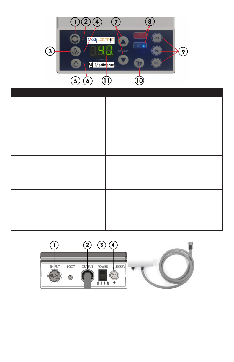
DISPLAY AND CONTROLS
NO. DESCRIPTION FUNCTION
1 Rotational direction Used to select a rotational direction (Fwd/Reverse)
of the micromotor.
2Micromotor operation direction. Displays the direction of the micromotor.
3Micromotor LED ON/OFF button Used to turn on and off LED.
4Micromotor LED indicator Indicates whether micromotor LED is running (LED
On signals LED is turned on).
5Spray On/Off button Used to switch on or off the spray function.
6Spray indicator Displays the operational state of the spray function;
water is sprayed when it is On.
7 Speed controller Used to set the operating speed of the motor.
8 Indicator of gear ratio selection Displays the selected gear ratio of the handpiece.
9Memory program selection button. Used to save the program values set in the memory
and select the saved program.
10 Gear selection button Used to select the gear ratio of the handpiece
connected to the motor.
11 Speed indicator Displays the operating speed of the handpiece.
Rear
NO. DESCRIPTION FUNCTION
1 Tubing connector-standard 4-hole
handpiece hose connector
Connect to handpiece hose from dental unit to
supply air & water, tubing connector per ISO
9168 type 3
2 Motor tubing / cable Motor tubing/cable, supplies power to the
motor, distributes air and water (it cannot be
separated from the control unit.)
3Power switch Main power switch for unit.
4Adapter connector Through which power gets supplied from the
adapter.
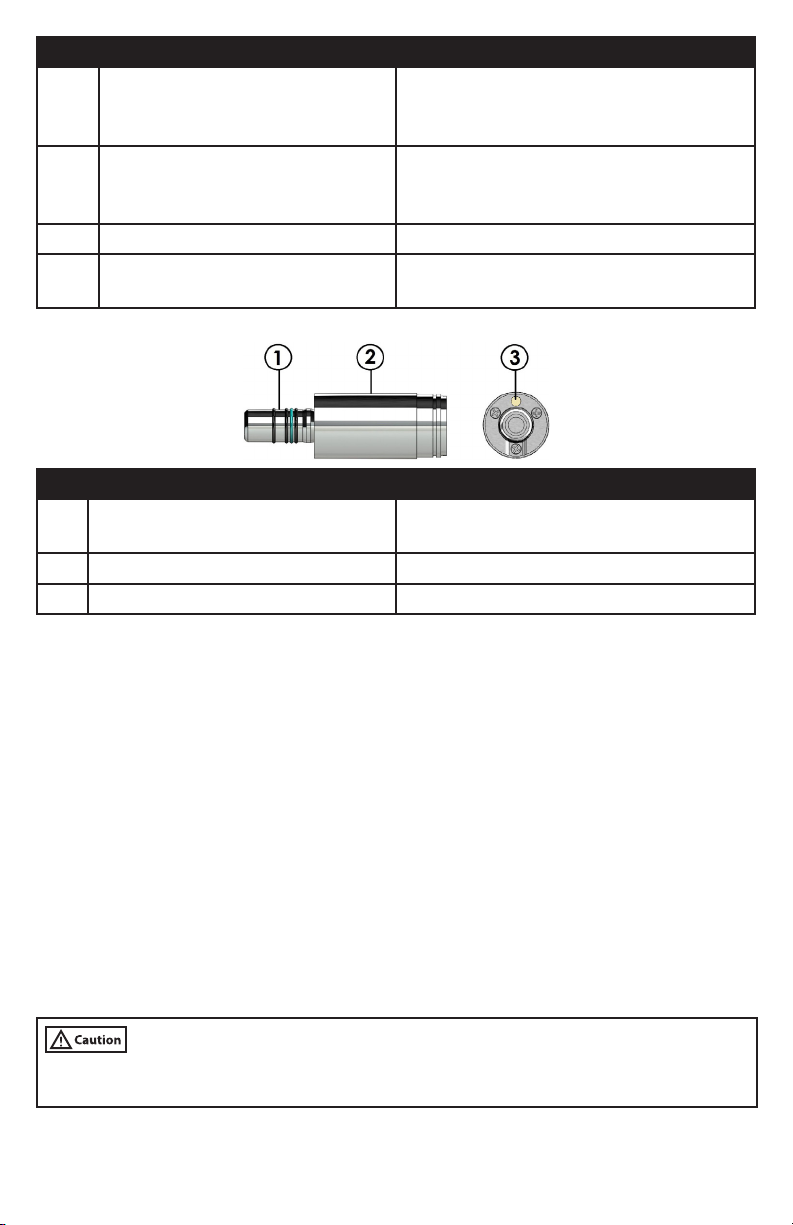
Micromotor
NO. DESCRIPTION FUNCTION
1Handpiece coupling connector Connect micromotor and a handpiece per ISO
3964 type 3
2Body Convert electrical energy to rotational motion
3Led Provide light
Additional Device Information
1. Type of protections against electric shocks Class I equipment
2. Degree of protections against electric shocks type B applied parts
3. Mode of operation Continuous operation
4. Applied parts
Handpiece: Used in connection with a micromotor Handpiece sold separately.
Environmental Conditions (Storage, Relocation, Operation,Shelf-life)
1. Storage condition
Temperature : 0°C ~ +50°C Humidity : 10 ~ 80% Air pressure : 500hPa ~ 1060hPa
2. Relocation conditions
Temperature : 0°C ~ +50°C Humidity : 10 ~ 80% Air pressure : 500hPa ~ 1060hPa
3. Operation conditions
Temperature : +10°C ~ +35°C Humidity : 30 ~ 80% Air pressure : 700~1060 hPa
4. Shelf-life
1 year based on standard fatigue shelf life of bearings the key components in the micromotor.
• Operation of the device in an environment other than those specified by manufacturer may
damage the device.

INSTALLATION & SET UP
• Check for damage to the cable and the connection pins prior to connecting with the
micromotor.
• Check system connection diagram and cable / motor connection illustration below prior to
installation.
System connection diagram
1. Medilectric Control box
2. Micromotor and hose
3. AC/DC Adapter 4-AC power plug
Connecting the micromotor with a cable / tubing and handpiece
1. Identify slot on micromotor and pin on motor tubing
connector (Fig.1)
2. Align and insert the pin on motor tubing connector
into slot on the motor terminal (Fig.2)
3. Turn the motor back nut clockwise to secure the
connection. (Fig.3)
4. To attach a handpiece (handpiece sold separately ) to
the micromotor, identify guide stud on handpiece and
hole on micromotor. (Fig. 4)
5. Lightly press the handpiece against the micromotor
while turning it slightly counterclockwise until the
guide stud click and lock into the hole . Pull the hand-
piece back to make sure the handpiece is securely
attached to the micromotor . (Fig.5) The micromotor
coupling is designed to fit most E-Type electric hand-
piece for dental procedure with coupling standard per
ISO 3964 type 3
Fig. 1
Fig. 2
Fig. 3
Fig. 4
Fig. 5

Handpiece Tubing Connector
1. Confirm that the delivery system tubing matches with
the back terminal of the control unit for connection
(Fig. 6) (coupling connection per ISO 9168 type 3
standard 4-hole handpiece hose)
2. Connect the tubing to the control unit and secure the
connection to prevent the air or water leakage (Fig.7) Fig. 6
Fig. 7
Connecting the AC/DC adapter Connection
• Only use power adapter supplied with this unit.
1. Insert the AC/DC adapter plug into the adapter
connector (Fig. 8)
Fig. 8
GENERAL OPERATION / PRECAUTIONS
Speed adjustment (Main function)
1. The speed can be set up to a maximum of 40,000 rpm (1:5 : 200,000 rpm, 1:1 : 40,000rpm)
by pressing the speed control button on the display.
Setting a rotational direction
1. The direction of the micromotor can be set by pressing the rotational direction selection
button on the control panel when the motor is not running.
2. When rotational direction indicator light is off, the motor is running in forward direction
(clockwise)
Setting optic LED On/Off
1. The LED installed in the micromotor can be turned on or off by pressing the OPTIC button on
the control panel.
Setting indicator for gear ratios of handpiece
1. The gear ratio can be displayed as 1:5, 1:1 depending on the gear ratio of the handpiece
selected with the use of the control panel.
2. The gear ratio can be adjusted to 1:5, 1:1 in a sequential order each time the operator
presses GEAR button. The selected gear ratio is highlighted.
Setting water spray
1. The water spray function can be turned on or off by pressing the SPRAY button on the
display. Selection of the program mode
2. Press and hold the button for selecting micromotor’s operational direction and the LED on/off
button simultaneously for 3 seconds or longer..
Memory program
1. How to save memory program : Customize settings of rotational direction, optic and so on;
Press and hold one of the three program buttons M1, M2, or M3 for 3 seconds or longer.
2. How to retrieve pre-saved program : Select the saved program by pressing P1, P2 or P3
button.
CLEANING & MAINTENANCE
Manual cleaning
NOTE:
• The Micromotor is provided Non-Sterile
• Clean and disinfect the micromotor and tubing before first use and after each patient
• Sterilize the motor after manual cleaning and disinfection.
• Routinely monitor dental unit water quality to ensure microbial counts are below the
levels for drinking water recommended by your local agency. The U.S. Centers for Disease
Control and Prevention (CDC) recommends a level of <500 CFU/ml of heterotrophic water
bacteria.
• After each patient use, disinfect the tubing waterlines include the handpiece and micro-
motor waterlines by flushing with cleaning water to prevent cross-contamination according
to handpiece waterlines disinfection procedure of main dental unit.
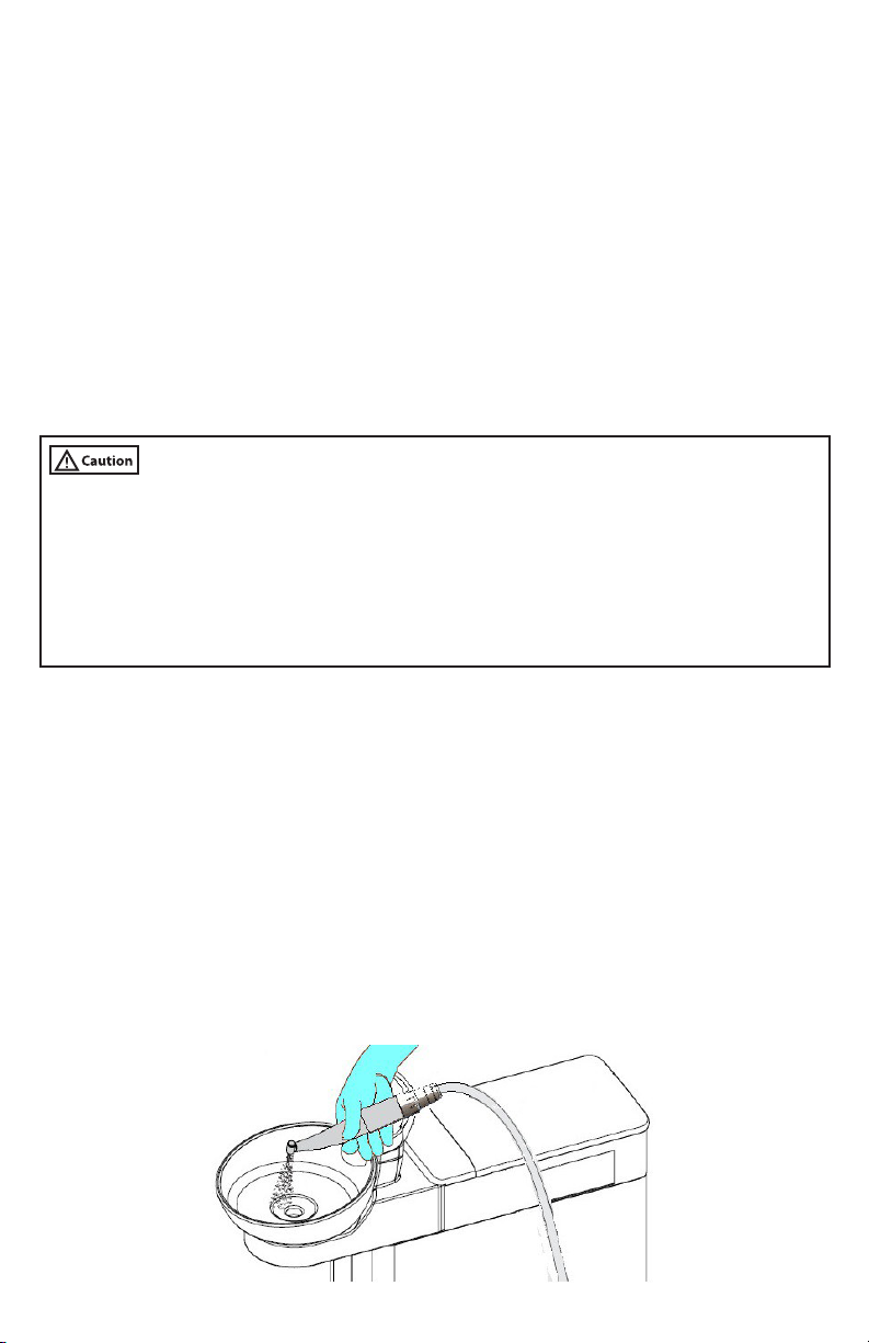
Manual internal cleaning for micromotor and motor tubing:
1. Internal cleaning waterlines , the Medilectric System must be conducted through the
main dental unit by connecting to standard 4 hole handpiece connector and follow the
instruction for handpiece and hose waterlines disinfection of the main dental unit.
(using the same procedure to disinfect waterlines of high speed handpieces on main dental
unit)
+ It is recommend to use Waterline Maintenance Tablets for main dental unit, it is the simple
way to maintaining clean dental unit waterlines.
2. Do not remove attached handpiece and the micromotor from the connecting cable during
internal waterlines cleaning and disinfection procedure.
3. Hold the handpiece with micromotor over the cuspidor or over a watertight container on main
dental unit with sufficient capacity and press the purging key on the main dental unit. Setting
time to clean and disinfect the waterlines base on manual instruction of main dental unit.
(Fig.9)
Fig. 9

Manual external cleaning for micromotor and motor tubing:
Recommendation for external cleaning accessories:
• Clean cotton cloth
• Soft brush-Nylon Bristles
• Alcohol 70% Isopropyl
• Protective glove uses during cleaning procedure.
1. For control box, micro motor cable / tubing (non removable) can be disinfected by wiping off
using soft cotton cloth with isopropyl alcohol.
2. For the micromotor, Disconnect the motor from the motor cable / tubing by turning motor
back nut counter- clockwise and gently pull the motor out. (Fig.10)
Fig. 10
• Use air spray to purge the waterline & remove excessive moisture from the micromotor. (Fig. 11)
• Use soft brush with isopropyl alcohol to clean exterior surface then wipe off with soft cotton
cloth.
• Visual inspection the cleanness of the micromotor prior to sterilization cycle.
Fig. 11
Fig. 12
STERILIZATION:
• Micro motor must be sterilized before first use and between each patient use by moist heat
accordance with ISO 17665-1 in a steam sterilizer (Autoclave)
• After manual cleaning(internal & external cleaning), follow the instruction below to autoclave
the micromotor:
1. Autoclave using Air Removal Steam type Sterilizer (pre-vacuum)
• Insert the motor into sterilization bag and load into autoclave. (We recommended using steril-
ization bag with at least one paper side.) The motor should be processed in the autoclave set
for a minimum of 4 minutes at a sterilization temperature of 1320C / 2700F and a minimum
dry time of 30 minutes.
2. For sterilization of attachment handpieces:
• Follow sterilization instructions provided by the manufacture of the handpiece.
Note: Replace the O-ring if
• Water or air leaks occur,
• The handpiece vibrates abnormally,
• The supply of water or air cannot be stopped, or
• It is difficult to install or remove the handpiece.

• There is no specific replacement period.
Changing the O-ring
To replace the motor O-rings: (Fig.13)
Fig. 13
1. Squeeze the O-ring together between your thumb and forefinger to form a loop.
2. Pull the O-ring off the motor.
3. Repeat steps 1 and 2 for the other three O-rings.
4. Slide on the new O-rings
NOTE: Always replace all four O-rings to ensure a secure connection between the motor and
attachment.
To replace the two small O-ring at the motor connection
back end: (Fig. 14)
1. Lift up the O-ring with a pair of tweezers and remove
the O-ring.
2. Carefully replace the two O-ring with new ones.
Fig. 14
NOTE: The ISO 11498 standard stipulates a durability of at least 250 sterilization cycles. We
recommend that you have the Medilectric Micromotor serviced after 500 sterilization cycles
or one year, whichever comes first.
TROUBLESHOOTING
Error Message Reference Guide Types of Errors
ERROR CODE STATUS CAUSE OF ERROR REMEDY
E1 Micromotor connec-
tion error
Poor connection with
cable / tubing
Visually check
the micromotor
connection.
E2 Micromotor defect Poor micromotor
connection or micro-
motor damage
Replace the micro-
motor if the micro-
motor connection has
no issues.
E3 Micromotor overload Micromotor is being
overloaded
Stop running the
micromotor and
restart after cooling
it down for 3-5
minutes.
Descriptions of Malfunctions
MALFUNCTION TYPES CAUSE OF ERROR REMEDY
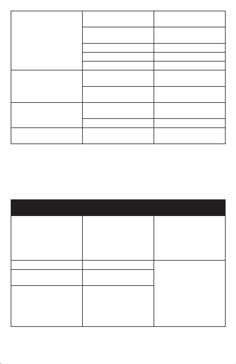
When the micromotor is not
running
Poor connection with a power
cable Check the power connection.
Poor connection with the
connection cable
Check the connection condi-
tion with the cable.
Control panel malfunction Contact the manufacturer.
Controller malfunction Contact the manufacturer.
Micromotor malfunction Contact the manufacturer.
When the micromotor speed
can’t get controlled.
Poor connection of the
connection code.
Check the connection
condition.
Control panel malfunction Contact the manufacturer for
a repair request.
When micromotor rotational
direction cannot be changed.
Poor connection with the
connection code.
Check the connection
condition.
Control panel malfunction Contact the manufacturer.
When the optic LED is not
working.
Failure of LED inside the
micromotor Contact the manufacturer.
ACCESSORIES
570-0685 Micromotor 570-0686 AC/DC Adapter 570-1058 O-ring Kit
ELECTROMAGNETIC COMPATIBILITY
Electromagnetic Emission
The product is suitable for use in a specific electromagnetic environment. The customer and/
or the user of the product should assure that it is used in an electromagnetic environment as
described below.
EMISSION TEST COMPLIANCE ELECTROMAGNETIC
ENVIRONMENT GUIDANCE
RF-emission CISPR 11 Group 1
The product use RF energy
only for its internal function.
Therefore, its RF emissions
are very low and not likely
to cause any interference in
nearby electronic equipment.
RF-emission CISPR 11 Class A The product is suitable for
use in all establishments,
including domestic estab-
lishments and those directly
connected to the public
low-voltage power supply
network that supplies build-
ings used for domestic
purpose.
Harmonic emissions IEC
6100-3-2 Class A
Voltage fluctuations/ flicker
emissions IEC 61000-3-3 Complies
Electromagnetic Immunity
The product is suitable for use in a specific electromagnetic environment. The customer and/
or the user of the product should assure that it is used in an electromagnetic environment as

described below.
IMMUNITY TEST EC 60601-LEVEL COMPLIANCE LEVEL ELECTROMAGNETIC
ENVIRONMENT
GUIDANCE
Electrostatic
discharge(ESD)
IEC61000-4-2
± 6kV contact
± 8kV air
± 6kV contact
± 8kV air
Floor should be
wood, concrete or
ceramic tile. If floors
are covered with
synthetic material,
the relative humidity
should be at least
30 %
Electrical fast
transient/bursts
IEC61000-4-4
± 2kV for power
supply lines
± 1kV for input/
output lines
± 2kV for power
supply lines
± 1kV for input/
output lines
Mains power quality
should be that of
a typical commer-
cial and/or hospital
environment
Surge IEC61000-4-5 ± 1kV differential
mode
± 2kV common mode
± 1kV differential
mode
± 2kV common mode
Mains power quality
should be that of
a typical commer-
cial and/or hospital
environment
Voltage dips, short
interruptions and
voltage variations
on power supply input
lines IEC61000-4-11
<5% UT (>95% dip in
UT) for 0.5 cycle 40%
UT (60% dip in UT)
for 5 cycles 70% UT
(30% DIP IN UT) for
25 cycles
<5% UT (>95% dip in
UT) for 5 sec
<5% UT (>95% dip in
UT) for 0.5 cycle 40%
UT (60% dip in UT)
for 5 cycles 70% UT
(30% DIP IN UT) for
25 cycles
<5% UT (>95% dip in
UT) for 5 sec
Mains power quality
should be that of
a typical commer-
cial and/or hospital
environment. If the
user of the product
requires continued
operation during
power mains inter-
ruptions, it is recom-
mended that the
product be powered
from an uninterrupted
power supply or a
battery.
Power frequency
(50/60 Hz) magnetic
field IEC 61000-4-8
3A/m 3A/m Power frequency
magnetic fields
should be at levels
characteristic of a
typical lo - cation in a
typical commercial or
hospital environment.

IMMUNITY TEST EC 60601-LEVEL COMPLI-
ANCE LEVEL
ELECTROMAGNETIC ENVIRONMENT
GUIDANCE
Conducted RF
IEC 61000-4-6
Radiated RF IEC
61000-4-3
3 Vrms
150 kHz
to 80 MHz 3V/ m
80 MHz
to 2.5 GHz
3 Vrms
3 V/m
Portable and mobile RF communi-
cations equipment should be used
no closer to any part of the product,
including cables, than the recom-
mended separation distance calcu-
lated from the equation applicable to
the frequency of the transmitter.
Recommended separation distance: d
= 1.2√P
d = 1.2√P for 80 MHz to 800 MHz d =
2.3√P for 800 MHz to 2.5 GHz
where P is the maximum output
power rating of the transmitter in
Watt (W) according to the transmitter
manufacturer and d is the recom-
mended separation distance in meters
(m) Field strengths from fixed RF
transmitters, as determined by an
electromagnetic site survey a, should
be less than the compliance level b in
each frequency
range Interference may occur in the
vicinity of equipment marked with the
symbol described lateral
Note 1: At 80 MHz and 800 MHz, the higher frequency range applies.
Note 2: These guidelines may not apply in all situations. Electromagnetic propagation is affected
by absorption and reflection from structures, objects, people and animals.
a-Field strengths from fixed transmitters, such as base stations for radio (cellular/cordless)
telephones and land mobile radios, amateur radio, AM and FM radio broadcast and TV broadcast
cannot be predicted theoretically with accuracy. To assess the electromagnetic environment due
to fixed RF transmitters, an electromagnetic site survey should be considered, if the measured
field strength in the location in which the product is used exceeds the applicable RF compliance
level above, the product should be observed, additional measures may be necessary, such as
reorienting or relocating the product.
b-Over the frequency range 150 kHz to 80 MHz, field strengths should be less than 3 V/m.
Recommended Separation Distances between portable and mobile HF- communications equip-
ment and the product
The product is intended for use in an electromagnetic environment in which radiated
RF disturbances are controlled. The customer or the user of the product can help prevent elec-
tromagnetic interference by maintaining a minimum distance between portable and mobile RF
communications equipment (transmitters) and the product – according on output power and
frequency of the communications equipment – as recommended in the following table.

Rated maximum output
power of transmitter in
watts (W)
Separation distance according to the frequency meters (m) of trans-
mitter in meters (m)
150 kHz to 80 MHz d
= 1.2√P
80 MHz to 800 MHz d
= 1.2√P
800 MHz d = to 2.5
2.3√P
GHz
0.01 0.12 0.12 0.23
0.1 0.38 0.38 0.73
11.2 1.2 2.3
10 3.8 3.8 7.3
100 12 12 23
PRODUCT DISPOSAL GUIDELINE
Disposal of Medical Devices
1. Follow your country specific laws, directives, standards and guidelines for the disposal of
used electrical devices
2. Ensure that the parts are not contaminated on disposal
Disposal of the packaging material
1. All packaging materials have been selected considering environmental protection and can
be recycled. Please send old/used packaging materials to the collection and reprocessing
centers appropriate per local laws and regulations to minimize waste.
WARRANTY
This product is designed for use in a dental office and this warranty is not applicable to other
uses. This product is warranted against manufacturing defects in materials and workmanship for
2years from date of purchase.
Medidenta will repair or replace product at its sole discretion. This warranty shall be limited
to replacement or repair of the product or its parts and shall not extend to any other claims,
including but not limited to loss of profit, cost of removal or replacement, incidental or conse-
quential damages or other similar claims arising from use of this product. Damage to product
resulting from acts of God, faulty installation, misuse, tampering, accident, abuse, negligence,
alterations, unauthorized repairs or problems unrelated to materials and workmanship are not
covered by this warranty.
Distributed by
MADE
IN
SOUTH
KOREA
Medidenta
731 Pilot Rd, Ste L
Las Vegas, NV 89119
IFU-MEDILECTRIC
001
REV.
11/19
Phone: 800-221-0750
Fax: 702-749-8610
Table of contents
Other Medidenta Media Converter manuals

Popular Media Converter manuals by other brands


H&B
H&B TX-100 Installation and instruction manual

Bolin Technology
Bolin Technology D Series user manual

IFM Electronic
IFM Electronic Efector 400 RN30 Series Device manual

GRASS VALLEY
GRASS VALLEY KUDOSPRO ULC2000 user manual

Linear Technology
Linear Technology DC1523A Demo Manual

Lika
Lika ROTAPULS I28 Series quick start guide

Weidmuller
Weidmuller IE-MC-VL Series Hardware installation guide

Optical Systems Design
Optical Systems Design OSD2139 Series Operator's manual

Tema Telecomunicazioni
Tema Telecomunicazioni AD615/S product manual

KTI Networks
KTI Networks KGC-352 Series installation guide

Gira
Gira 0588 Series operating instructions

Lika
Lika SFA-5000-FD user guide