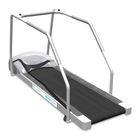
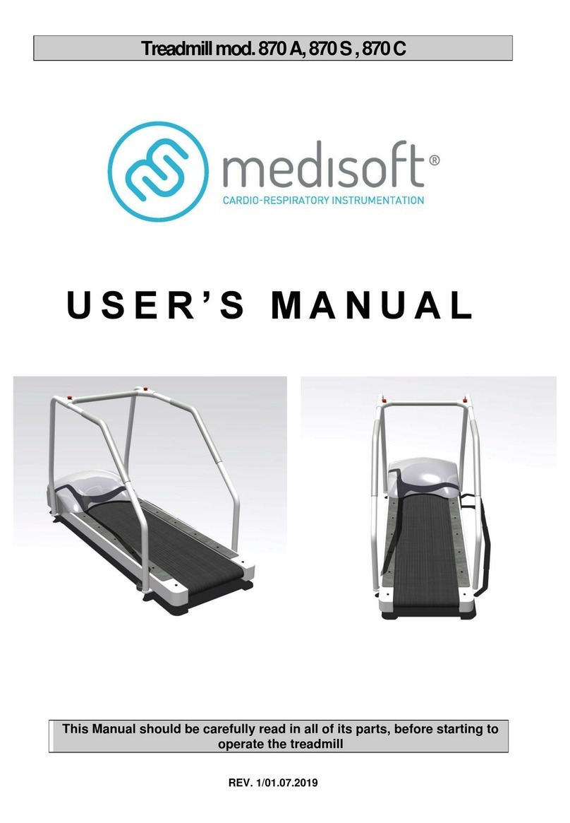
Medisoft 800 Series User manual

© Medisoft RAM Italia S.r.l. - All rights reserved 1
800 Series Treadmills
Annual routine
maintenance
Mod. 870 A –870 S –870 C
REV. 1/01.07.2019

This manual has been carefully written and checked.
Nevertheless no responsibility is assumed for possible
inaccuracies.
All rights reserved. No part of the contents of this
document may be reproduced or transmitted in any
form or by any means without the written permission of
Medisoft RAM Italia S.r.l.
The Medisoft RAM Italia S.r.l. company is committed to
a policy of constant improvement in compliance to
Norm ISO EN 9001:2001 requirements, and as a
function of feedback from customers and the market in
compliance to norm ISO EN 13485:2004. As a
consequence, the company reserves the right to make
changes to this document and to the products
described herein without notice.
Validity date : 29/07/2017

TABLE OF CONTENTS
Annual routine maintenance for the series 800 Treadmills
1Introduction ........................................................................................................................4
2Flowchart............................................................................................................................5
3Frequency of use Check ........................................Errore. Il segnalibro non è definito.7
4Removal of Hood ...............................................................................................................7
5Cleaning of Motor Compartment .......................................................................................8
6 Incline of Treadmill............................................................................................................8
7Cleaning of Cooling Fan ....................................................................................................8
8Lubrification screw actuator...............................................................................................9
9Last maintenance check....................................................................................................10
10 Disassembly of Gliding System .......................................................................................10
11 Replacing of running belt................................................................................................11
12 Disposal of running belt ..................................................................................................12
13 Deck cleaning...................................................................................................................12
14 Lubrication of Deck..........................................................................................................12
15 Cleaning of Rollers and Checking the Bearings..............................................................13
16 Replacing of Running Belt...............................................................................................14
17 Cleaning of Running Belt.................................................................................................14
18 Drive Belt wear check ......................................................................................................15
19 Replacement of Drive Belt...............................................................................................15
20 Restoring the Gliding System...........................................................................................15
21 Gliding System Check and lubrication.............................................................................16
22 Tautness Check of Drive Belt...........................................................................................17
23 Tautening of Drive Belt....................................................................................................17
24 Tautness Check of Running Belt......................................................................................18
25 Tautening of Running Belt...............................................................................................18
26 Closing..............................................................................................................................19
27 Maintenance planning –Critical parts……………....…………………………………. 20

© Medisoft RAM Italia S.r.l. - All rights reserved
4
1 Introduction
The main objective of the maintenance tasks herein described, is to keep the 800 series treadmill
in perfect working order, and to guarantee a top performance of the exercise device. These tasks
are particularly important when it comes to checks and inspections of the condition of the
equipment and the potential need to replace the moving components that are most subject to wear
and tear. Most of the components that will require periodic replacement are located below the
treadmill deck, where proper maintenance will continue to allow the belt to glide over the deck,
and its elevation to be raised or lowered.
These maintenance tasks are also fundamental in order to guarantee the duration and safety of the
device, and as a consequence, the annual maintenance is in fact mandatory.
Performing these tasks requires the opening of the hood where the motor is located, in order to
access the electromechanical components of the device. For this reason, and for the delicate
nature of these types of procedures, these tasks must be performed exclusively by the qualified
technicians of the Customer Service.
The maintenance tasks are summarized in the following table.
No.
Task
1
Cleaning of the motor compartment
2
Checking of the gliding system.
The flowchart in the following paragraph shows the sequence of events that are further explained
in detail in other paragraphs of this document.
In order to use this document correctly it is not possible to remove from consideration the
flowchart in question since many paragraphs are of practical use only within the sequence of
events we are following. It is therefore necessary to use this document by first following the
sequence illustrated in the flowchart and by consulting each single paragraph on the basis of its
related sequence.
WARNING:
When working with the device connected, we must take the following precautions:
1) use tools with insulated handles
2) wear specific personal protective clothing and equipment, such as insulated gloves and
shoes.

© Medisoft RAM Italia S.r.l. - All rights reserved 5
OK
not OK
not OK
OK
not OK
OK
2 Flowchart
Start A
3 Frequent.-of-use
check
Replacement of the
treadmill is advisable
Stop
4 Removal of the hood
5 Cleaning of the motor
compartment
6 Incline of the treadmill
7 Cleaning of the cooling
fan
8 Lubrication screw
actuator
10 Disassembly of the
gliding system
11 R.B. wear check
12 Disposal of the
running belt
13 Deck cleaning
13 Deck cleaning
14 Lubrication of the
deck
15 Cleaning of the rollers
and check of the bearings
17 Cleaning of the
running belt
14 Lubrication of the
deck
18 Lubrication of the
running belt
6 Incline of the treadmill
16 replacing the running
belt
19 D.B. wear check
20 Replacement of the
drive belt
21 Restoring the gliding
system
Start B
9 Last maintenance check

© Medisoft RAM Italia S.r.l. - All rights reserved
6
OK
non OK
non OK
OK
non OK
OK
Start B
Stop
24 Tautening of the drive
belt
27 Closing
22 Gliding system check
23 Tautness check of D.B.
26 Tautening of the
running belt
25 Tautness check of R.B.

© Medisoft RAM Italia S.r.l. - All rights reserved 7
3 Frequency of the use check
A treadmill should last 6/8 years based on the level of utilization and environmental conditions..
In the event that the treadmill has been used intensely for more than seven years, the check result
must be considered NOT OK and it is advisable to replace the exercise device itself. If the
treadmill has been used for less than seven years than the check result is OK.
4 Removal of Hood
Necessary tools:
•Philips screwdriver
•Screwdriver
Fig.1
Fig.2
In order to remove the motor hood cover, the following steps must be taken, in the order indicated:
1) turn off the treadmill by turning the main switch to the OFF position
2) unplug the power plug
3) unscrew the screws of the RS232 connector on the hood and remove the connector (Fig.1)
4) remove the hood by unscrewing the four screws found at its base (Fig.2)
5) re-insert the connector in the serial port RS232 on the motor box
Should the hood come off prior to having executed operations 1) and 2), a security switch will
interrupt the power to the treadmill. The main switch will remain under tension and the warning
light will remain on to signal the operator that it’s necessary to follow the operations listed above in
1) and 2).
WARNING:
Before proceeding with the troubleshooting operations (for elevation or rotation problems of the
treadmill) it is necessary to check the right connections of the flat cables that join the serial board
to the power board.
This check is performed opening the protection boxes containing the serial board and the power
board. Transportation could cause the disconnection of the flat cables and in this case it will be
necessary to reconnect them, to close the protection boxes and to recheck the treadmill functions.

© Medisoft RAM Italia S.r.l. - All rights reserved
8
5 Cleaning of Motor Compartment
Essential tools:
•Vacuum cleaner with a crevice tool attachment
Use the Vacuum cleaner with a crevice tool attachment to remove dust and debris that might build
up on the bed of the motor compartment.
6 Incline of Treadmill
In order to execute the elevation check it is obviously necessary that the treadmill is under tension
and should the hood be open, it is necessary to act very carefully. To apply tension, with the cover
open, the following operations must be executed, in order:
1) block the security contact in the closet position (Fig.3)
2) connect the power plug
3) turn the main switch to the ON position
WARNING:
At this moment, the machine is under tension and you are advised to act very carefully in order to
avoid accidental contact with the parts under tension.
The elevation check can be performed utilizing the software from the PC in order to send an
elevation command to the treadmill. If the treadmill elevates itself in the proper way after the
command is given, the elevation check is considered OK; otherwise not OK.
After the execution of the check and given that one must still work on the treadmill with the cover
open, it is recommended to remove the tension following these steps:
1) turn off the treadmill (put the main switch in the OFF position)
2) Unplug the power plug
Fig.3
7 Cleaning of Cooling Fan
Essential tools:
•Vacuum cleaner with a crevice tool attachment
Locate the cooling fan attached to the speed motor. Use the vacuum cleaner to free the vent
protective grate from debris.

© Medisoft RAM Italia S.r.l. - All rights reserved 9
8 Inclination actuator screw lubrication
Tools needed:
•10mm Allen key
•19mm wrench
•Grease
Get the treadmill up to 23,5 of inclination and folds the treadmill on his hip (fig.4).
With the 19mm wrench and the 10mm Allen key unscrew the stem fixing the actuator (fig.5).
Unscrew and remove the actuator’s stem and use the grease for lubricate it. (fig.6-7).
Cleaning the actuator screw, insert and fasten the stem on the screw.
Grease the screw and finally proceed with mounting and fixing the actuator at the cart. (Fig.8).
During this operation pay attention at the correct position of the limit switch 25%.
Fig.4 Fig.5
Fig.6 Fig.7
Fig.8

© Medisoft RAM Italia S.r.l. - All rights reserved
10
9 Last maintenance check
If it has been more than 3 years from date of purchase or last revision of the gliding sistem, the
test is not OK.
If less than three years the test is OK.
10 Disassembling the gliding subsystem
Essential tools:
• Wrenches from 5.5, 10 and 13 mm
• Allen keys 3, 4, 6, 8 mm
• Screwdriver
• Phillips screwdriver
Remove the plastic screw caps on the side plates of the treadmill, so that the screw heads are
easily reached.
Unscrew and remove the screws that secure the laterals plastics on the treadmill, then remove
them.
Use an 8 mm Allen wrench to loosen the screws that secure the rear roller to the frame. These
screws are located underneath, in the rear side of the treadmill (Fig.9).
With a 13 mm wrench remove the bolts tend running belt located at the foot of the treadmill.
Loosen the rod registration of the belt tensioner support , then remove the 2 screws that secure it
to the floor and remove it.
Use the 8 mm Allen wrench to unscrew and remove the screws that hold the front roller to the
frame, then remove it.
Use the 10 mm wrench to unscrew and remove the screws on the brackets at the foot of the
treadmill (Fig.10). Remove both brackets and set them aside.
Use the 8 mm Allen wrench to unscrew and remove the screws that secure the rear roller and the
protective plate to the frame. Set aside the protective plate and remove the rear roller.
Use the 3 mm Allen wrench to remove the left elbow of the emergency button.
With the 4mm Allen wrench and 13mm wrench, remove the handlebar left rear side.
Use the 5,5mm wrench to remove the protective cover of the main switch in order to access
internal screws.
At this point we remove the extension of the frame with 6mm Allen key and 17mm wrench, first
removing the screws that secure the motor box and then removing the screws that secure it to the
frame member (Fig. 11 - 12 ).

© Medisoft RAM Italia S.r.l. - All rights reserved 11
Lift the rear of the treadmill and put under the foot right-thick 3 or 4 cm (Fig. 13).
We can now remove the running belt for a waxing treatment or replacement (Fig.14).
Fig.9 Fig.10 Fig.11
Fig.12 Fig.13 Fig.14
11 Replacing of Running belt
The tape should be replaced if:
• Have 5 or more years of use
• Damaged or in poor condition
• Particularly damaged interior surface (Fig.15)
Fig.15
The new running belt don’t need any lubrication. In fact all running belt starting from S.N. 11081
starting from 2011 are already be lubricated from the producer.

© Medisoft RAM Italia S.r.l. - All rights reserved
12
12 Disposal of running belt
Essential tools:
•Scissors
This is the procedure to make unusable the running belt.
Cutting by scissors.
13 Deck Cleaning
Essential tools:
•Brush
•Sandpaper
•Vacuum cleaner or compressor
Through the use of sandpaper, the surface of the base will be folded away, eliminating as much as
possible the residue of the old wax and any other impurities.( fig. 16)
With the use of the brush you will remove from the surface of the deck all the accumulation of dust
and dirt that will be created. This operation will be repeated until all the old waxy material is
removed. For a better cleaning result, it is advisable to use a vacuum cleaner or compressor to
effectively remove dust from the machine that you have created with this process. (fig. 17)
Fig. 16 Fig.17
14 Lubrication of Deck
Essential tools:
•Rubber gloves
•Iron wax
•Ram Wax HP3 Blue
•Protective gear: face mask, glasses and gloves
•Cleaning paper
This operation can only be carried out on treadmill made from 2009 with a S.N. greater than or
equal to 10143. If the bottom is older or has been treated with silicone lubricant it must be replaced.

© Medisoft RAM Italia S.r.l. - All rights reserved 13
The operation must be carried out in a ventilated environment using protective mask and rubber
gloves.
Use the roll of paper to perfectly clean the deck surface.
Connect the iron wax to the mains voltage by setting a temperature of about 100 degrees through
the adjustment knob.
With the help of the iron, melt evenly over the entire surface of the bottom about 125g
Ram Wax HP3 blue (Fig. 18), which corresponds to about half a soap.
Always with the iron wax, melt and spread evenly the wax until the wood has absorbed all the
wax it needs (Fig. 19). This operation will be completed when a thin paraffin surface is created,
indicating the full absorption of the wax.
Fig.18 Fig.19
15 Cleaning of Rollers and Checking the Bearings
Essential tools:
•Cleaning cloth
•Wooden wedge
Manually set the rollers in motion and place your ear next to where the spherical bearings are
located. If the motion causes a very distinct noise due to the rolling of the spheres, it is necessary to
proceed to replace the rollers.
The cleaning of the rollers can be made by scraping the surface with a wooden wedge to remove
any debris and dirt stuck to the surface of the roller themselves. Finish the cleaning by wiping the
surface with a cloth (Fig.16).

© Medisoft RAM Italia S.r.l. - All rights reserved
14
Fig.16
16 Replacing of Running Belt
We can now insert a new running belt, making sure that the write "MS" appears on the right side
of the treadmill.
17 Cleaning of Running Belt
Essential tools:
•Cleaning cloth
•Brush
The cleaning of the running belt must be performed using brush and a cleaning cloth (Fig.21).
Fig.21

© Medisoft RAM Italia S.r.l. - All rights reserved 15
18 Drive Belt Wear and Tear Check
This check consists of a visual check of the wear-and-tear conditions of the drive belt. Conditions
must be checked on the inner side of the belt, which is the part that touches the drive pulleys. It is
necessary to check the surface of the belt lengthwise.
If the inner surface shows cracking and defects, the check result must be considered NOT OK,
otherwise the check result is OK.
19 Replacement of Drive Belt
Essential replacement parts
•Drive belt Poly V
Detach the drive belt completely from the motor pulleys as well and replace it with a new belt.
20 Restoring the Gliding System
Essential tools:
•Cross-head screwdriver
•Flat blade screwdriver
•5,5, 10 and 13mm wrench
•3, 4, 6, 8mm Allen wrench
Apply the extension spar previously removed.
Insert the rear roller into the running belt, supporting the shaft in its position on the frame, insert
the protective plate of the roller and restore without blocking the screws.
Restore the two brackets previously removed from the end of treadmill and fix with 10mm wrench
Apply the screws with your head 13mm, but without to tension the running belt.
Insert the front roller into the running belt, supporting the shaft in its position on the frame.
Fit a new transmission belt on the front roller pulley, then apply the screws onto the front roll
without even tighten them. Fit the transmission belt also in the motor pulley.
Apply the handlebar and the plastic elbow removed earlier.
Position the belt tensioner support on motor box and apply the screws without tightening them
yet.
Tighten the belt tensioner bolt to tension the belt temporarily.
Apply on the surface of running belt two pieces of paper tape at a precise distance of 1000mm.

© Medisoft RAM Italia S.r.l. - All rights reserved
16
Before everything, put in the middle the running belt on the wooden bottom, then use the 13 mm
wrench, alternately tighten the bolts tend tape at the feet of the treadmill.
The tension of the tape must be verified by the measure of the same between the two applied
references, which should be 7 mm (the original measure 1000, the final measure 1007).
At this point it is necessary to put in rotate the running belt to adjust the trim of the same
horizontal.
To rotate the tape is necessary to work at hood open and the machine is working. To apply the
voltage, do the following in sequence:
1) the safety contact block in the closed position
2) connect the plug to the socket
3) turn the switch to ON
WARNING:
From this moment on, the machine is under tension, and you are advised to be extremely careful
in order to avoid accidental contact with the parts under tension
If the belt was lubricated, make sure that before it is set into motion, the surface is perfectly
dry, otherwise we must wait for the surface to dry completely.
After putting the tape in rotation (2 Km / h), you must check that the belt remains centred between
the wheels of directionality placed under the frame.
If the running belt is not centred, you have to screw one of the two bolts that tensioner the belt and
precisely the opposite to that in which you want to get the displacement of the tape.
To check that the running belt is perfectly aligned and parallel to the side stringers, observe the
directional guides. If during the rotation, the tape don't touch the guide, meaning that the tape is
perfectly aligned and it isn't necessary to adjust, otherwise must be adjust.
Once you have the belt alignment is necessary to tighten the screws that secure the front roller
and the rear roller to the frame
Reposition the side plates and fix them to the wooden deck with the previously removed screws.
Put the plastic screw caps back.
21 Gliding System Check and lubrication
To perform this check it is necessary to set the belt in motion.
To set the belt in motion it is necessary to work with the hood open and the device switched on. If
the treadmill is not switched on, follow the guidelines described in paragraph 6.
Do get on tape a person at least 100kg and put it into rotation at a speed of 0.5 km/h (0.3 Mph).
If these conditions regularly runs the carpet (no cracks), while the operator walks on the tape, the
test is OK.
Otherwise, if the running belt is blocked or not flowing properly, the test is not OK.

© Medisoft RAM Italia S.r.l. - All rights reserved 17
22 Tautness Check of Drive Belt
This check is carried out by setting the belt in motion to verify if the drive belt slips or not when
operating at full load.
To set the belt in motion it is necessary to work with the hood open and the device switched on.
To turn the device on, follow the sequence of tasks indicated below:
1) lock the safety contact into closed position
2) connect the plug to the mains
3) turn the main switch to the ON position
WARNING:
From this moment on, the machine is under tension, and you are advised to be extremely careful
in order to avoid accidental contact with the parts under tension
After having set the belt in motion (1,6 Km/h), we must climb on the belt and forcefully stop the
belt temporarily with our feet(Fig.22).
During this operation you need to check that the drive belt , the flywheel, the roller and the running
belt work perfectly.
If all the components listed above are running at the same time then the test is OK..
Fig.22
23 Tautening of Drive Belt
Essential tools:
•10mm wrench
Switch off the treadmill by performing the following tasks:
1) turn the main switch to the OFF position.
2) disconnect the plug from the mains.
3) release the safety contact to the position open.
Use a 10mm wrench to loosen the screws that secure the support of the belt tensioner roller
containment tank engines.

© Medisoft RAM Italia S.r.l. - All rights reserved
18
Loosen the nut of the adjusting rod (Fig.23), then screw it up to put in the proper belt tension.
Screw the nut and the screws that secure the support of the roller belt tensioner to the engine
containment tank.
Fig.23
24 Tautness Check of Running Belt
To perform this check it is necessary to set the belt in motion, to verify if the running belt slips or
not on the front roller when operating at full load.
To set the belt in motion it is necessary to work with the hood open and the device switched on. If
the treadmill is not switched on, follow the guidelines described in paragraph 6.
After having set the belt in motion (1,6 Km/h), we must climb on the belt and forcefully stop the
belt temporarily with our feet(Fig.22).
During this operation you need to check that the drive belt , the flywheel, the roller and the running
belt work perfectly.
If all the components listed above are running at the same time then the test is OK..
25 Tautening of Running Belt
Essential tools:
•13-mm wrench
To perform this check it is necessary to set the belt in motion.
To set the belt in motion it is necessary to work with the hood open and the device switched on. If
the treadmill is not switched on, follow the guidelines described in paragraph 6.
Start the treadmill and adjust the running belt with the two bolts illustrated (Fig. 21) until the lower
surface of the tape (the one under the wood base) is perfectly horizontal and parallel to the surface
of the fund (Fig.22).

© Medisoft RAM Italia S.r.l. - All rights reserved 19
During this operation check that the belt remains centred between the wheels of directionality
placed under the frame.
Is important to know that the tape moves in the opposite direction to the bolt we're screwing
Fig.21 Fig.22
26 Closing the hood
Essential tools:
•Cross-head screwdriver
•
Turn off the treadmill turning the switch to position OFF, then remove the plug from the socket.
Insert the lateral cover to the wood base with the screws removed earlier, then insert the plastic
screws caps.
Make sure all the components available have been closed properly.
Unlock the safety switch by removing the previously inserted cable tie.
Before closing the hood, make sure that the connector on the RS232 is disconnected otherwise
would not be possible to close the hood.
Close the hood of the treadmill then tighten the 4 screws.
Reconnect the connector on the RS232 port.

© Medisoft RAM Italia S.r.l. - All rights reserved
20
27 - Maintenance planning –Critical parts
Frequency
Type of maintenance
Person
1 year
1 year preventive general maintenance
User
1 year
1 year cleaning maintenance
User
1 year
1 year control test
User
3 years
3 years replacement of critical parts
Approved technician
Critical Parts
Medisoft
Reference
Quantity
Group replacement front roller
800070-RIC (870A)
800072-RIC (870S)
800074-RIC (870C)
1
Group replacement rear roller
800080-RIC (870A)
800082-RIC (870S)
800084-RIC (870C)
1
Wood base treated
800162 (870A)
800164 (870S)
800166 (870C)
1
Running belt
800140 (870A)
800142 (870S)
800144 (870C)
1
Other manuals for 800 Series
1
This manual suits for next models
3
Table of contents
Other Medisoft Treadmill manuals
Popular Treadmill manuals by other brands
Weslo
Weslo Cadence 815 Treadmill LIVRET D'INSTRUCTIONS

Sunny Health & Fitness
Sunny Health & Fitness SF-T7945 user manual
Tunturi
Tunturi RUN 3.0 user manual
Pro-Form
Pro-Form Crosswalk 425 X PMTL32706.0 user manual

Life Fitness
Life Fitness 9000 Service manual

HEALTH RIDER
HEALTH RIDER H150t Treadmill user manual
Smooth Fitness
Smooth Fitness 9.65LC user manual
BLADEZ
BLADEZ BLADEZ T4 PRO Illustrated parts manual
HEALTH RIDER
HEALTH RIDER H200T HETL14915.0 user manual

Pro-Form
Pro-Form 1010 Zlt Treadmill Manuel de l'utilisateur
Pro-Form
Pro-Form 1050t Treadmill manual
ICON Health & Fitness
ICON Health & Fitness PRO-FORM PRO 2000 user manual
