Medizintechnik ATMOS Strobo 21 LED User manual

ATMOS Strobo
21 LED
GA1GB.150211.0
2019-07 Index: 30
Operating Instructions
English
These operating instructions are valid for ATMOS Strobo 21 LED 2nd generation.

ATMOS
MedizinTechnik GmbH & Co. KG
Ludwig-Kegel-Straße 16
79853 Lenzkirch
Germany
Phone +49 7653 / 689-0
Fax: +49 7653 / 689-190
+49 7653 / 689-393 (Service Center)
www.atmosmed.de

3
Table of contents
1.0 Introduction.........................................................4
1.1 Notes on operating instructions ............................4
1.2 Intended use .........................................................4
1.3 Function ................................................................5
1.4 Explanation of pictures and symbols ....................5
2.0 For your safety....................................................6
3.0 Setting up and starting up .................................7
3.1 Scope of supply ................................................... 7
3.2 Connections..........................................................7
3.3 Mounting the holder for light handle......................7
3.4 Starting up.............................................................8
3.4.1 Connection Diagram ATMOS Cam 31 DV DATA
and ATMOS Strobo 21 LED ..................................9
4.0 Operation...........................................................10
4.1 Switchingonando............................................10
4.2 Functions of display ............................................10
4.2.1 Display during phonation ....................................10
4.2.2 Display after phonation .......................................10
4.2.3 Adjustment of display..........................................11
4.3 Examination ........................................................12
4.3.1 Sequence............................................................12
4.3.2 Resolution / Brightness control ..........................13
4.3.3 Handling the foot switch......................................14
4.3.4 Operation with other light sources ......................14
5.0 Cleaning and care.............................................15
5.1 General information on cleaning and
disinfection..........................................................15
5.2 Unit......................................................................15
5.3 Chemical disinfection..........................................15
5.4 Surface disinfectants...........................................15
6.0 Maintenance and Service.................................16
6.1 Replacing the fuse ..............................................16
6.2 Period tests.........................................................16
6.3 Sending in the device..........................................16
7.0 Troubleshooting................................................17
8.0 Accessories and spare parts...........................18
8.1 Accessories.........................................................18
8.2 Spare parts .........................................................18
9.0 Technical data ...................................................19
10.0 Disposal.............................................................20
11.0 Notes on EMC....................................................21

4
1.1 Notes on operating instructions
1.2 Intended use
1.0 Introduction
These operating instructions contain important notes on how to operate the ATMOS Strobo 21 LED,
correctlyandeectively.Theirreadinghelpstoavoidrisks,andalsotoreducerepaircostsanddown-
times. This increases, amongst other things, the reliability and service-life of the device.
These operating instructions serve not only for new operating personnel to be instructed in its use, but
also for use as a reference manual. Reprints (also in extracts) only with permission in written form by
ATMOS.
These operating instructions must always be kept available near the device.
Care and safety inspections in conjunction with professional execution provide for operational safety
and readiness for use of your ATMOS Strobo 21 LED and are therefore a must besides regular
cleaning.
Repair work and safety inspections may be carried out only by expert personnel authorised by ATMOS.
By applying only original spare parts you will have the guarantee that operational safety, readiness for
work and the value of your ATMOS Strobo 21 LED will be preserved.
• The product ATMOS Strobo 21 LED bears CE marking CE according to the EC Directive of the
council for medical products 93/42/EEC and meets the basic requirements of Appendix I of the
directive.
• The product ATMOS Strobo 21 LED complies with all applicable requirements of the Directive
2011/65/EC restricting the use of certain hazardous substances in electrical and electronic
equipment (“RoHS”).
• The declaration of conformity and our general standard terms and conditions can be obtained on
our website at www.atmosmed.com.
• ThequalitymanagementsystematATMOShasbeencertiedaccordingtointernationalstandards
EN ISO 13485.
• Prior to start-up please peruse chapter 2.0 „For your safety“, in order to be prepared for any
possible dangerous situations.
In the following all device versions, as well as all modules and table-top devices are named ATMOS Strobo 21 LED!
Name: ATMOS Strobo 21 LED
Main functions: Stroboscopic diagnostics of the larynx
Medical indications / application:
Examination of the larynx
Specication of the main function:
The adjustment of requested phases or slow motion for
examination is set by means of a foot regulator. Along with
corresponding endoscopes and video components, the
sequence of examination can be watched on a monitor and
be recorded.
Application organ: Examination of the larynx
Application time:
The duration of the examination (stroboscopy) is set as
“temporary” (max. 60 minutes).
Application site:
In clinics and practices for ENT doctors and phoniatricians.
The stroboscope may only be operated and applied by
medicallytrainedsta.
Contraindications:
Not for use outside of medical areas.
Not for use in explosion-hazardous areas of medically-used
rooms.
The product is: active
Sterility: Not necessary
Single-use product / reprocessing:
No single use product

5
!
~
click
1.3 Function
The product consists of a control module with control
elements,thesetoLEDlightemitterandthemicrophone.
The emitter and the microphone are both connected to
the control element with an electric cable. Another control
element is the foot controller which is also connected to
the control element. The activation of a video recorder is
possible with the connection of the optionally available
professional foot controller.
Thedevicehastwodierentmodi,thesearepermanent
light mode or stroboscopy mode. As soon as there is no
microphone trigger signal, the device automatically switches
over from the stroboscopy mode to permanent light mode.
There are two functions in the stroboscopy mode: freeze-
image and slow-motion. In the permanent light mode the
LED stroboscope can be used as light source.
An airborne sound microphone (alternatively a structure-
borne sound microphone – stethoscope microphone) picks
up the sound signal produced by the proband. With this
sound signal a trigger signal is produced to activate the light
source, the basic frequency respectively the sound-pressure
level is obtained In the display the determined values for
the basic frequency respectively the sound-pressure level
and the operation mode (freeze image, slow motion resp.
permanent light) are indicated.
1.4 Explanation of pictures and symbols
Graphic symbols contained in this manual
Signal output
Freeze (Storage)
Foot switch
Signal input and output
O(feed-in,power
connection)
On (feed-in, power
connection)
Alternating current
Ground wire connection
Warning, special diligent notice
Follow operating instructions (blue)
Application part type BF
Fuse according to IEC 417/5016,
DIN 30600/0186
Potential equalisation
Short cuts / symbols contained in these operating instructions
Please press where
dot indicates
Follow the arrows
Activate the optional foot
switch Replace
Check
Please read,
important information
Move, plug... in this
direction
Engage, check
correctt
Turn, shift ... in this
direction
1.0 Introduction

6
General safety information
2.0 For your safety
Risk of injury!
Danger to the device!
!
• ATMOS neither guarantees for fault-free
operation nor for personal injuries and
damage to property if:
- no original ATMOS parts are being used
- the advice for use in these operating
instructions is not being observed,
- assembly, new settings, alterations,
extensions and repairs have been carried
out by personnel not authorised by ATMOS.
• The ATMOS Strobo 21 LED is:
- designed in line with IEC 601 / EN 60601.
- assigned to VDE safety class I
- and the class I (93/42/EWG).
• The ATMOS Strobo 21 LED meets the
immunity to interference requirements of IEC
601-1-2 / EN 60601-1-2 „Electromagnetic
Compatibility – Medical Electrical Devices“.
• Please check the delivery on completeness
and intactness.
• Please note:
A medical insulating transformer with earth
leakage monitor or any similar safety
system acc. to EN 60 601-1 is required, if
several devices are connected over one
common power supply. The transformer must
correspond to the power consumption of all
the devices to be connected.
• The ATMOS Strobo 21 LED may only be
usedunderthesupervisionofskilledsta
who have been authorised by ATMOS and
trained in its operation (IEC 601-1 / EN
60601-1).
• There are no warranty claims whatsoever
on defects which arise from the use of third
party accessories or consumables.
• When connecting several devices on one
grounding receptacle, the allowed strain and
leakage current have to be observed.
• Pay also attention to the safety information of
the attached devices / parts as well as to the
safety informations in the following chapters.
• The ATMOS Strobo 21 LED may be operated
only in rooms used for medical purposes,
but not in areas subject to explosion hazards
and in oxygen rich environments.
• All additional equipment which is connected
to the analogue and digital interfaces of
the device must meet the requirements
ofrelevantENspecications(forinst.EN
60950 for data processing equipment and
EN 60601 for electrical medical appliances).
Inaddition,congurationsmustsatisfy
systemspecicationEN60601-1-1:2001.
When additional equipment is connected
to the signal input or signal output section
on the device, the person carrying out
the connection is deamed „a system
congurationoperator“andassuchis
responsible for meeting the requirements of
systemspecicationEN60601-1-1:2001.
For answers to additional questions, please
contact your local specialist supplier or the
ATMOS Technical Service.
• Do not allow any liquid to get into the unit. If
liquid has penetrated the unit, it may not be
operated again until it has been checked by
the customer service centre.
• If the endoscope is used combined with
energetic operated accessories the patient
leakage current can sum up.
• Never look directly into the light source!
• Never touch the device´s interfaces and the
patient at the same time!
• Priortorststartingup,allconnectingleads
must be checked on damage. Damaged
cables must be replaced! Check functions of
the device prior to using it!
• The treating doctor is responsible for the
proper procedure and technology! The
adequacy and the kind of application must
be decided by a trained doctor according to
circumstances.
• Priortocleaning,switchothedeviceand
separate it from the mains supply resp. from
other devices.
• Thexationofmicrophonemayjustbe
tightened enough as absolutely necessary
for the function.
• Only endoscopes which previously have
been cleaned and disinfected may be stored
in the quivers.
• To disconnect the device from the mains
supply,rstremovetheplugfromthewall
outlet. Disconnect the connection line on the
device afterwards only. Never touch plug or
cable with wet hands!
• The ATMOS Strobo 21 LED may be operated
only in rooms used for medical purposes, but
not in areas subject to explosion hazards.
• This environment may be caused by the use
ofammableanaesthetics,skincleansing
products and skin disinfectants.
• Prior to each use check the outer surface of
all endoscope parts and endoscopic used
accessories parts which are implemented
in the patient. Make sure no harsh surface,
sharp-edged angles or salient parts are
existing, they may cause a danger.
• Please observe, it could happen that body
parts get caught in the foot controller!
• Switchothedevicewhenyounishyour
daily business.
• When installing the unit, make sure that
there is enough cooling air supply.
• The ATMOS Strobo 21 LED may not be
operated with devices not complying with
the requirements of standard EN 60601-
1 „Medical Electrical Equipment“ and EN
60601-1-2 „Electromagnetic Compatibility“
(Medical Electrical Equipment).
• The device may only be connected to a
properly installed protective contact socket.
• For mains supply, only use the power cable
supplied (or an equivalent one).
• Pay attention to the ambient conditions
speciedinchapter9.0.
• Please pay attention to the period tests in
chapter 6.0 „Service and maintenance“.
• Priortorststartingup,checkwhetherthe
mainsvoltagespeciedonthetypeplate
matches the local mains voltage.
• Check proper assignment when assembling
country-specicconnections:
- green / yellow: protective conductor (PE)
- blue: neutral conductor (N)
- black or brown: phase (L)
• Protect the device against direct solar
radiation and keep it away from heaters.
• Always set up the unit in such a way that
the operating elements are in clear view and
within easy reach of the operator.
Pay attention to maximum stability of the
installation surface.

7
C
D
E
F
G
H
I
J
K
3.0 Setting up and starting up
3.1 Scope of supply
Optional:
3.2 Connections
Backside
ForefrontControl panel
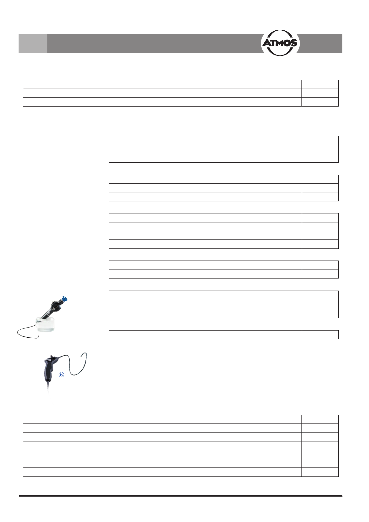
• Control unit
• Airborne sound microphone incl. clip for laryngoscope
• Light handle ATMOS LS 21 LED incl. adapter Wolf
• Holder for light handle LS 21 LED with switching function
(not applicable for ATMOS Roadster)
• Foot regulator
• Audio cable
• Power supply cord
• Impact sound adaptor for airborne microphone
• Holder for laryngoscope (1 quiver)
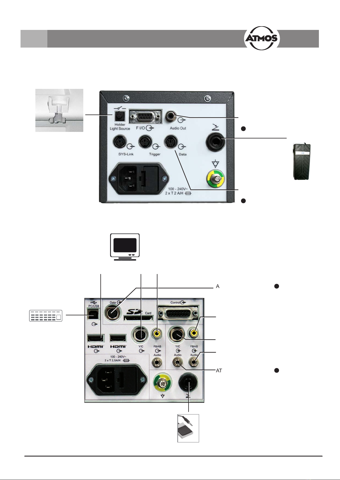
On/Oswitch
Adjustments
Control knob Indication for permanent light
Indication for freeze image
Indication for slow motion
Display
3.3 Mounting the holder for light handle (not applicable for ATMOS Roadster)
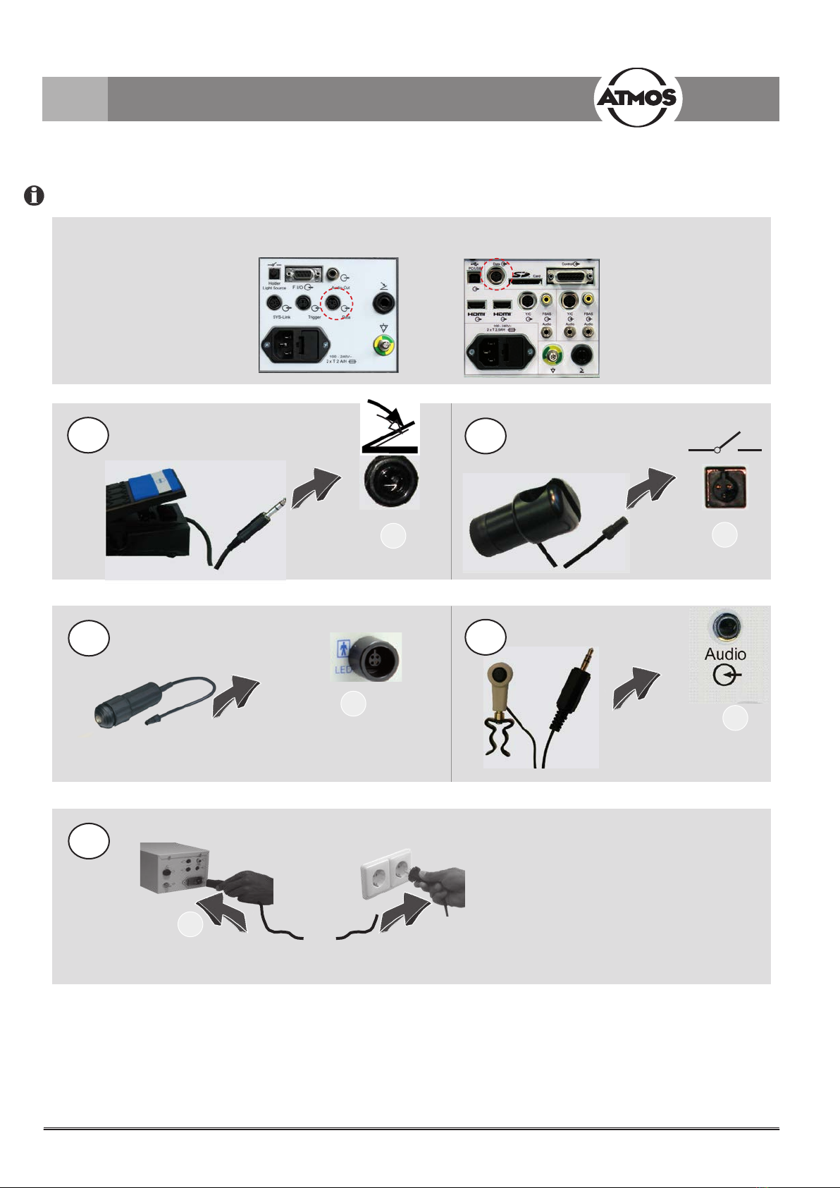
CConnection holder for light handle LS 21 LED with switching function
DOptional connection for the MediaStroboscope
EAudio output (Line-out)
FConnection for foot regulator
GDATA Interface
HNo function
INo function
JConnection for potential equalization
KNut for mains supply
AConnection for microphone
BConnection for LED light
handle
A
B
8
+
.....
1
B
34
5
2
K
A
C
F
ATMOS Strobo
21 LED
Please pay attention, just to switch on the devices after they have been completely wired.
3.0 Setting up and starting up
3. 4 Starting up
(not applicable for ATMOS Roadster)
(not applicable for
ATMOS Cam 21 / 31,
2. Generation)
ATMOS Cam 31 DV Data
3. Generation
9
ATMOS Strobo 21 LED
ATMOS Strobo 21 LED
ATMOS Strobo 21 LED
1
2
ATMOS Cam 31
DV Data
ATMOS Cam 31
DV Data
2
1
3.0 Setting up and starting up
Handle support
LED light source
ATMOS Strobo
LED
Foot
controller
3.4.1 Connection Diagram ATMOS Cam 31 DV Data, 3. Generation and ATMOS Strobo 21 LED
digital
Computer
MS-Windows 7 or higher
USB Streaming
ATMOSoft external microphone
REF 507.1806.0
S-video source (Y/C)
e.g. ATMOS i View
FBAS video source
e.g. ATMOS Scope
analogue
ATMOS Cam 31 DV Data
3. Generation
10
!
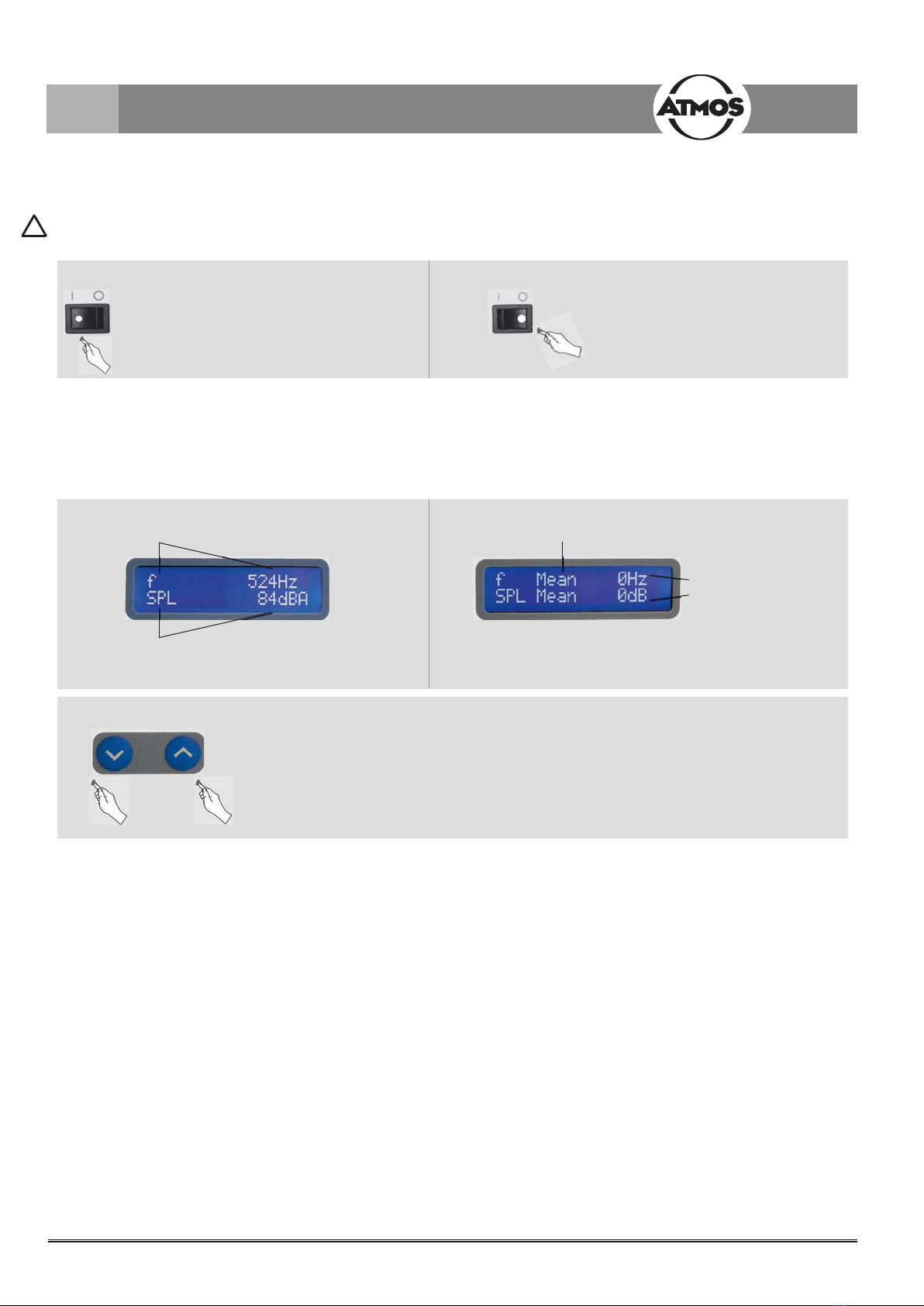
4.2 Functions of display
4.1 Switching on and o
4.0 Operation
mean frequency
and Ø-volume
after phonation
Ø-value
4.2.2 Indication after examination
Change of contrast
...or... push repeatedly
4.2.1 Indication during examination
Frequency
(pitch)
Volume
(Sound pressure level)
Prior to each use a function check has to be performed. See chapter 6.0 “Service and Maintenance”.
Switching on Switching o
After switching on the device it
takes a few seconds until it is
ready for operation.

11
+
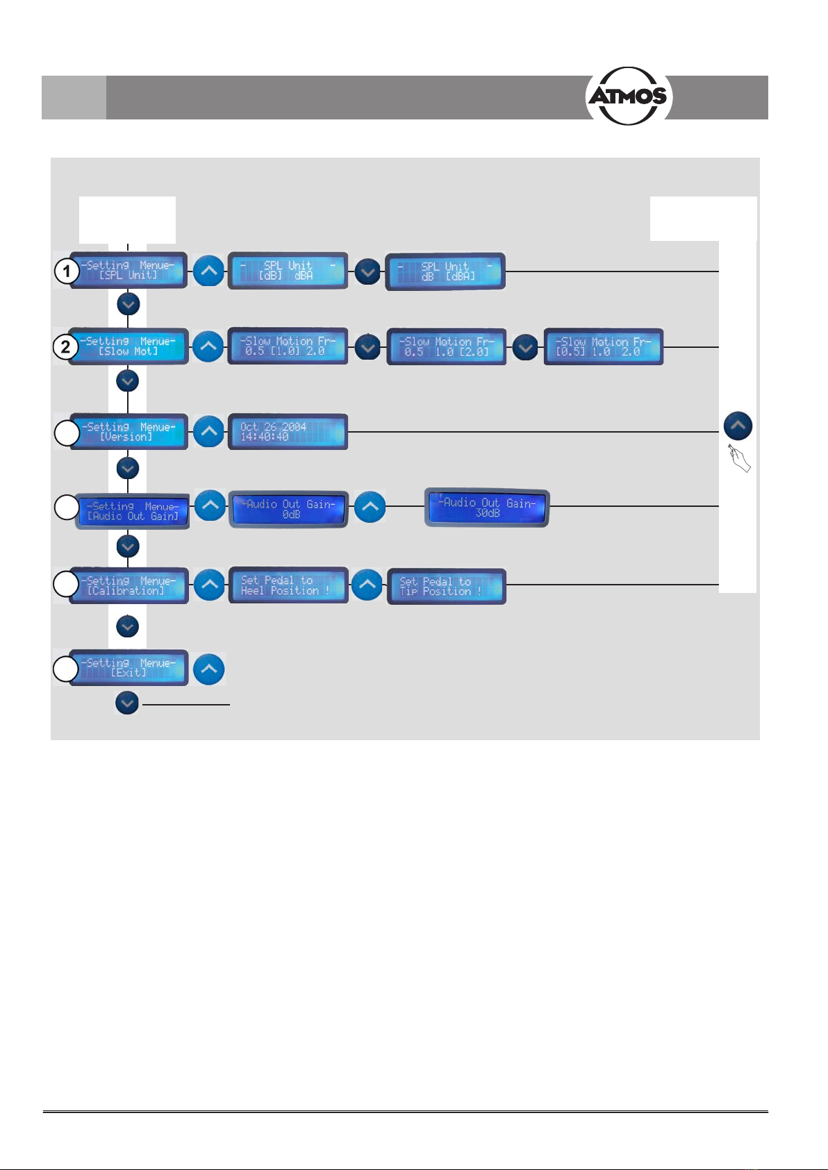
Adjustable submenus (see next page)
4.2.3 Setting menu
Access „Setting Menu“
The display
indicates
„Startup”
and keep
pressed
Select menu
Conrm,„Set“,
„Continue“
Select submenu
release key
4.0 Operation
1SPL Unit:
Setting dB or dBA
2Slow Motion:
Setting speed of slow motion
0.5: 1 oscillation / 2 sec
1.0: 1 oscillation / sec
2.0: 2 oscillations / sec
3Version:
Information about software version
4Audio Out Gain:
AmplicationoftheaudiosignalcanbeadjustedattheLINE-OUTaudiooutput.
Attention!IncasetheaudiosignaloftheLINE-OUTisamplied,thatistosayforalladjustmentsotherthan0
dB, the audio signal no longer corresponds to the sound level of the input signal which is shown in the display
respectively emitted at the data interface.
5Calibration:
Calibration of foot controller. Your supplied foot controller is already calibrated to your stroboscope. Please
follow the instructions in the display. Please take care to apply only low pressure for the stop positions. Prior to
conrmingthereachedstoppositionpleasewaitfor2seconds.
6EXIT:
End adjustments of menu
12
4...
3
5
6
Adjustment of menu
Changing the
submenu
Conrm / Back
to the relative
submenu
Exit the menu,
back to indication for examination
Display indicates
„Please switch o and on again“
4.0 Operation
13
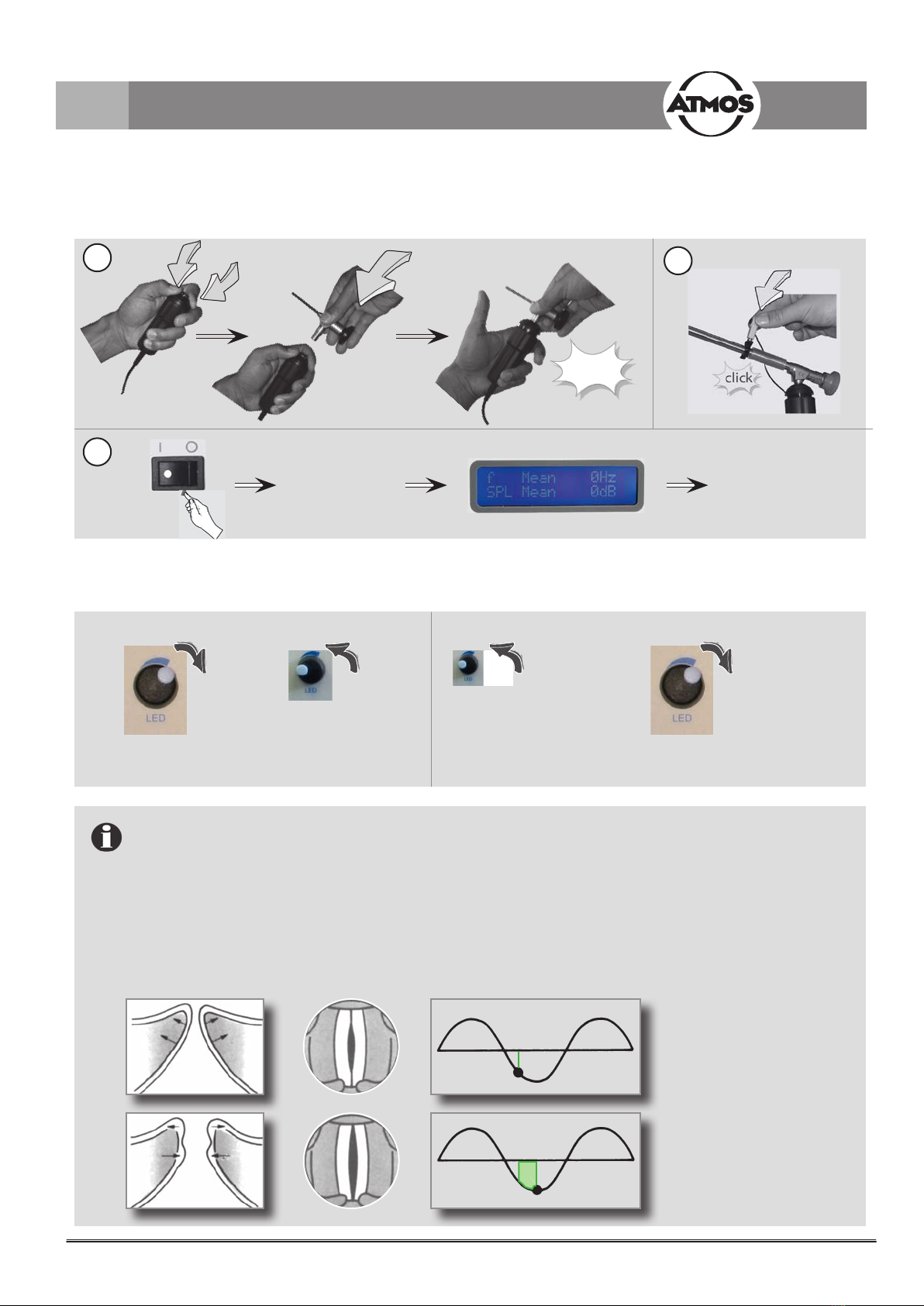
click
12
3
4.3.1 Operating sequence
4.3 Examination
Phonation
readomeasured
average values
4.3.2 Resolution / Brightness control
turn left slowly until
requested picture
adjustment is obtained
After switching on
turn right until limit stop
LED gets darker LED gets lighter
Operating mode of brightness control:
In case the picture becomes more blurred when the brightness is increased:
TheATMOSStrobo21LEDasheswith2Watt.Forgeneratingabrighterimage,theilluminationhastobelonger.
This entails that the vocal cord oscillates fractionally at this moment.
The tiny movement reclined during the exposure time is perceived blurred.
The darker the image, the shorter the exposure time, the shorter the reclined movement of the vocal cord, the well-
denedtheimage.
Adjustments
4.0 Operation
14
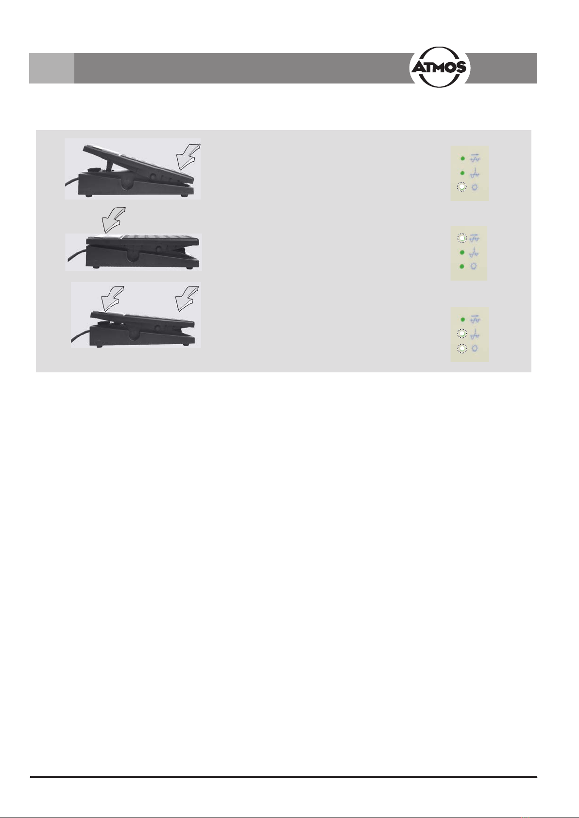
4.3.3 Operate the foot regulator
4.3.4 Operation with other light sources
Permanent light
Slow motion
Reectionofindividual
phases/positions of vocal cord
oscillations
4.0 Operation
The device can be operated with other ATMOS light sources or other ATMOS devices with integrated light sources e.g. with
an ATMOS Scope. During the operation with other devices the light handle ATMOS LS 21 LED can remain in the light source
holder.
15
1
+
+
5.1 General information on cleaning and disinfection
5.3 Chemical disinfection
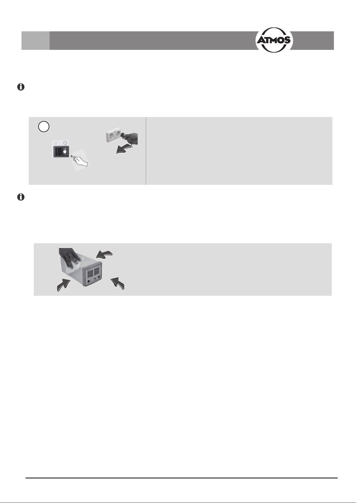
5.2 Unit
Do not use:
• Disinfectants which contain organic or inorganic acids or bases as they could cause corrosion damage.
• Disinfectants containing chloramides, phenol derivatives or anionic tensides, as these may cause stress cracks in the material
used for the housing of the unit.
Cleaning supplies,
see page 15
5.0 Cleaning and care
Prior to cleaning
...and all other
connected devices
• If required, wipe the camera with a cloth moistened with a cleaning
solution and disinfect the application parts which come into contact with
the patient. Do not spray the liquid directly on the device.
• For cleaning / disinfecting the optics please pay attention to the
respective cleaning instructions.
• For disinfection, you may use all surface disinfectants listed on page 15.
• Alwaysobservetheconcentrationspecicationsandinstructionsbythe
respective manufacturer!
• Avoid liquid residues in the snap-in connection of the video adaptor.
• Upon drying avoid liquid residues and spots on the lens of the image sensor.
• All surfaces may be cleaned with the disinfectants listed on page 15.
The composition of plastic, varnish and colours as well as cleansers and disinfectants change continuously. Therefore, prior to
rstusealwaystestthecleaningagentontheundersideofthedevice!
5.4 Surface disinfectants
• When using disinfectants containing aldehyde and amine at the same object colour changes may occur.
Disinfectant Ingredients (in 100 g) Manufacturer
Incidin®Plus
(Application concentrate)
Glucoprotamin
Nonionic tensides
Solvents, complexing agents
26.0 g Ecolab, Düsseldorf
Dismozon®pur
(Application concentrate)
End of product 2014-12
magnesium monoperoxyphthalate
hexahydrate
80 g Bode Chemie, Hamburg
Dismozon®plus
(Application concentrate)
magnesium monoperoxyphthalate
hexahydrate
95.8 g Bode Chemie, Hamburg
Green & Clean SK
(Application concentrate)
alkyl-dimethyl-benzyl-ammonium chloride
dialkyl-dimethyl-ammonium chloride
< 1 g Metasys, Rum (Austria)
16
+
... +
...
click
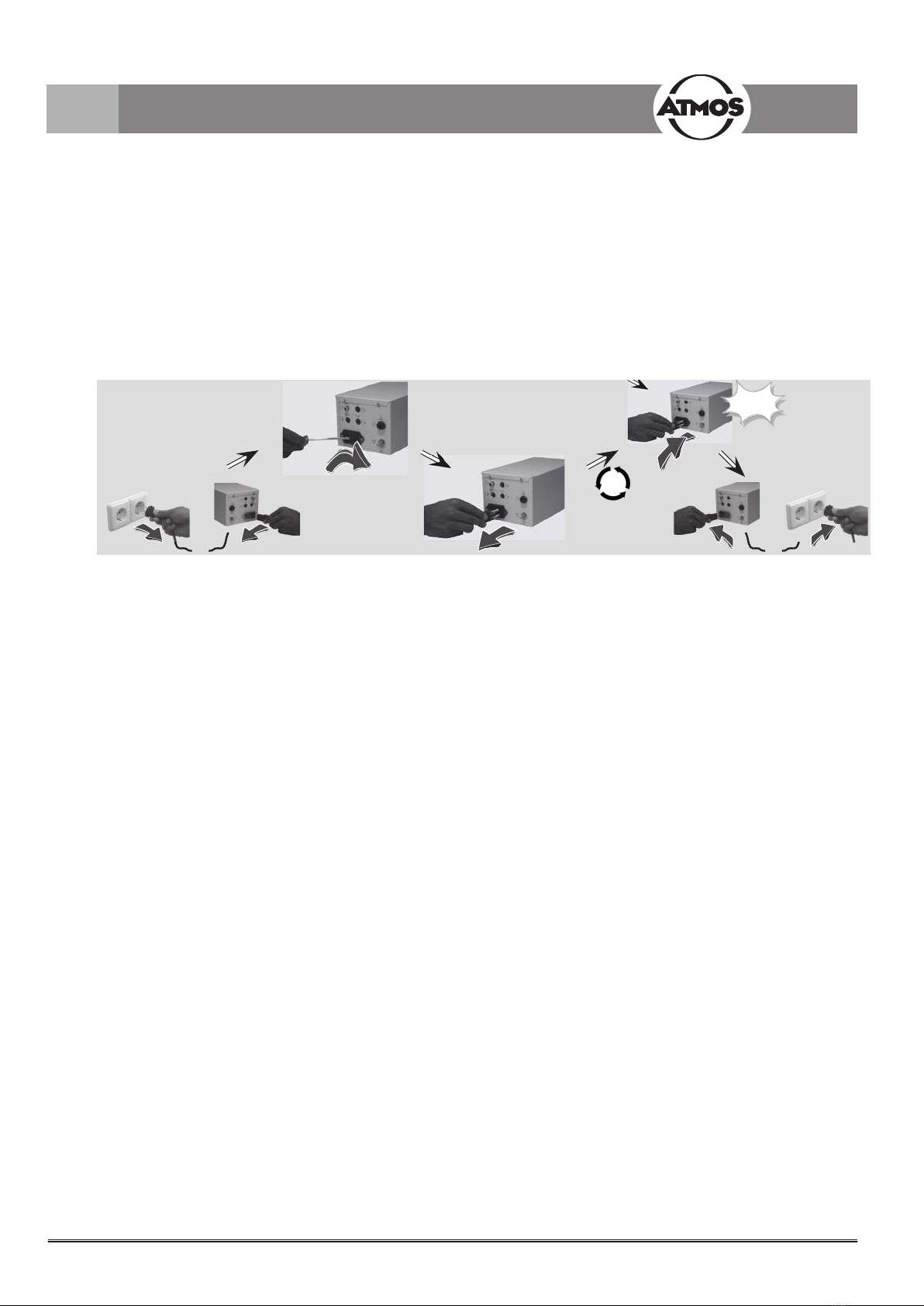
6.1 Replacing the fuse
6.0 Maintenance and Service
Always replace
both fuses!
Maintenance, repairs and period tests may only be carried out by persons who have the appropriate technical knowledge
and are familiar with the product. To carry out these measures the person must have the necessary test devices and original
spare parts.
ATMOS recommends: Work should be carried out by an authorized ATMOS service partner. This ensures that repairs and
testingarecarriedoutprofessionally,originalsparepartsareusedandwarrantyclaimsremainunaected.
At least every 24 months a repeat test of the electrical safety should be performed according to IEC 62353.
ATMOSrecommendsaninspectionaccordingtothemanufacturer‘sspecications.
Scope of test:
• Visual inspection of device and accessories on function-related mechanical defects.
• Checking the readability of safety-related labellings.
• Controlling the melt insert of the miniature fuse on the nominal current and the melting characteristics.
• Function control in compliance with the operating instructions.
• Measuring the ground wire resistance
• Measuring the earth leakage current: NC and SFC
• Measuring the patient leakage current: Type BF, NC and SFC
6.3 Sending in the device
• Remove and properly dispose of consumables.
• Clean and disinfect the product and accessories according to the operating instructions.
• Place used accessories with the product.
• Fill in the form QD 434 „Delivery complaint / return shipment“ and the respective decontamination certicate.
)This form is enclosed to each delivery and can be found at www.atmosmed.com.
• The device must be well padded and packed in suitable packaging.
• Place the form QD 434 „Delivery complaint / return shipment“ and the respective decontamination certicate in an
envelope.
• Axtheenvelopetotheoutsideofthepackage.
• Send the product to ATMOS or to your dealer.
6.2 Period tests
Medical devices like the ATMOS Strobo 21 LED must be fail safe at all times. Do not use the device if it is obviously damaged.
Prior to each use a function check has to be performed:
• Check whether the device or its cables are visibly damaged. Damaged cables have to be replaced immediately.
• Connect the microphone and sing a tone. The device has to show a constant frequency. As soon as you change the pitch
level, the frequency changes.
• Check whether the foot switch works as described in chapter 4.2.3.

17
7.0 Troubleshooting
Description Possible causes of error Measures
No indication from the device Powerplugisttedbadly Checkttingofthepowerplugatthemainspower
and at the device
No mains voltage available Check main fuse
Defect fuse Check fuses
Indication is illegible Insucientcontrast Adjust contrast by pressing the ‚up‘ and ‚down‘
button (see chapter 4.1.1).
Blurred image For technical reasons the vocal
fold oscillations / vocal fold
position are blurred if there
is an increase in brightness
during stroboscopy with the
LED light source, (see chapter
4.2.2 Resolution /brightness
control).
Reduce the brightness of the LED light source.
Foot controller is positioned at
„heel“, thereby the signal for
permanent light is generated.
Change to freeze image mode respectively slow
motion mode by moving the foot controller, see
chapter 4.2.3).
The acoustic signal is
not picked up properly /
microphone has not been
connected correctly.
Make sure, the microphone is properly connected
tothedevice,thatitisaxedcloseenoughto
the acoustic source and correctly aligned. Make
sure the operational reliability of the microphone
is given.
Acoustic signal cannot be
evaluated at all resp. cannot be
evaluated properly.
Use the optional obtainable contact microphone.
Image is too dark Brightness of the LED light
source is too low.
Enhance the brightness of the LED emitter by
triggering the control knob (see chapter 4.2.2).
Please observe the information there regarding
„Resolution / Brightness control“.
Foot regulator does not work Foot regulator is not connected
properly.
Check if foot regulator is connected properly.
Switchothedeviceandwait5secuntilswitching
it on again.
Foot regulator has not been
calibrated.
Implement calibration. (Enter the submenu
‚Calibration‘ (see chapter 4.1.3, „Adjustable
submenus“) and follow the indicated advices.)
18
8.0 Accessories and spare parts
8.1 Accessories
Optical instruments
Impact sound adaptor for airborne microphone 507.4775.0
Holder for laryngoscope (1 quiver) 507.2209.0
Dongle connector for interlink ATMOS Cam 21 / 31 507.4781.0
8.2 Spare parts
Airborne sound microphone 507.4780.0
Light handle ATMOS LS 21 LED 507.4600.0
Light handle ATMOS LS 21 LED, warm white 507.4602.0
Holder for light handle ATMOS LS 21 LED with switching function 507.4605.0
Foot regulator 507.4771.0
Power supply cord 507.0859.0
Audio cable 008.0858.0
Laryngoscopes
Laryngoscope HD 70°, Ø 8 mm, L = 190 mm 950.0254.0
Laryngoscope HD 70°, Ø 10 mm, L = 190 mm 950.0255.0
Laryngoscope HD 90°, Ø 10 mm, L = 190 mm 950.0256.0
Ear endoscopes
Otoscope HD 0°, Ø 4 mm, L = 50 mm 950.0257.0
Otoscope HD 30°, Ø 4 mm, L = 50 mm 950.0258.0
Otoscope HD 0°, Ø 2,7 mm, L = 50 mm 950.0259.0
Nose / Pharynx endoscopes Ø 4 mm
Sinuscope HD 0°, Ø 4 mm, L = 175 mm 950.0260.0
Sinuscope HD 30°, Ø 4 mm, L = 175 mm 950.0261.0
Sinuscope HD 45°, Ø 4 mm, L = 175 mm 950.0262.0
Sinuscope HD 70°, Ø 4 mm, L = 175 mm 950.0263.0
Nose/Pharynx endoscopes wide angle Ø 2.7 mm
Sinuscope HD 70°, Ø 2,7 mm, L = 110 mm 950.0264.0
Sinuscope HD 30°, Ø 2,7 mm, L = 110 mm 950.0265.0
Flexible endoscopes
High-resolution naso-pharyngoscope Ø 3.2 mm, working length: 300 mm,
0°,angleofeldofview:80°,depthoffocus:5mm–innite,angle:125°/
125°
Scope of delivery includes aluminium transport case and leak tester
950.0243.0
ATMOS Scope
Flexible video naso-pharyngoscope with integrated LED light source 950.0300.0
19
Operating voltage 100 - 240V, 50/60Hz
Current consumption (max.) 0.3 A/m
Input power 30 VA
Flash frequency 70 - 1000 Hz
Accuracyofdisplayingashfrequency +/- 1 Hz
Metering range of sound level 70 - 125 dB
Accuracy of the sound level display +/- 1dB
Power supply cord 2 m length, earthing contact plug, non-heating
Microphone Airborne sound microphone,
Impact sound adaptor optional
Modes of operation Continuous light; slow motion 0,5 up to 2 Hz; freeze image 0°- 400°
displacement of phase
Operation time Continuous operation
Models Table top unit (507.4700.0)
Assembly module for S 61 Servant (531.0159.0)
Fuse 2 x 2.0 A/H
Enclosure leakage current (max.) 0.1 mA NC
Patient leakage current (max.) 0.1 mA NC
Earth leakage current (max.) 0.5 mA NC
Heat release max. 30 Joule/s
Noise level No noise emission
Ambient conditions
Transport / storage
-30° up to 50°
5 bis 90% humidity without condensation
at an air pressure of 700 - 1060 hPa
Ambient conditions
Operation
5° up to 35°
20 bis 80% humidity without condensation
at an air pressure of 700 - 1060 hPa
Dimensions HxWxD 118 x 139 x 280
Weight 5 kg
Period tests Repeat test of the electrical safety every 24 months.
Recommended:inspectionaccordingtothemanufacturer‘sspecications.
Protection class (EN 60601-1) I
Degree of protection BF
Protection class IPX1
Classicationinaccordancewith
appendix IX EC Directive 93/42/EEC I
CE marking CE
UMDNS code 12-346
GMDN code 30008
9.0 Technical data

20
• The ATMOS Strobo 21 LED does not contain any hazardous materials.
• The component parts of the ATMOS Strobo 21 LED must be disposed
of correctly and the materials are to be separated carefully.
• The materials of the housing can be recycled completely.
10.0 Disposal
Table of contents
Other Medizintechnik Medical Equipment manuals

Popular Medical Equipment manuals by other brands


Milestone
Milestone STA manual

Weinmann
Weinmann MEDUVENT Standard manual

Mobility Research
Mobility Research LiteGait AutoStep quick start guide

3M Unitek
3M Unitek Ortholux Luminous Curing Ligh Instructions for use

Whitehall Manufacturing
Whitehall Manufacturing SP-1600-D-220 Operation and maintenance manual

ResMed
ResMed AirSense 11 Disinfection Guide


