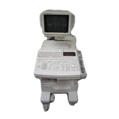
Medmont E300 User manual


Medmont E300 Corneal Topographer i
Table of Contents
1.MANUAL CONVENTIONS ........................................................................... 1
2.INTENDED PURPOSE ................................................................................... 2
Power Connection....................................................................................2
Standard E300 Accessories ......................................................................3
Optional System Accessories available from Medmont ..........................4
Spare Parts ...............................................................................................4
Consumables ............................................................................................4
The E300 Software...................................................................................5
Software Conventions 5
3.WARRANTY .................................................................................................... 6
4.IMPORTANT FACTS ..................................................................................... 7
Explanation of Symbols and Labels: 8
Regulatory Information 9
This instrument complies with all applicable Regulatory requirements
and Safety Standards. 9
Classification 9
Clinical Results 9
Accuracy and Calibration 9
Radiation 10
Electromagnetic Compatibility and Emissions 10
This instrument conforms to the EMC Standard IEC 60601-1-2. The
device emits no harmful or undesired electromagnetic emissions. 10
Interference 10
Side effects 10
Electrical safety of medical electrical system 10
Disposal 10
5.INSTALLATION ........................................................................................... 11
PC and Associated Equipment Requirements........................................11
Instrument Environment ........................................................................11
Software Installation ..............................................................................12
Running the Software 13
Connecting the E300 instrument............................................................13
Connecting the USB Video Converter box 13
Checking the E300 instrument is connected 13
Registering the E300..............................................................................14
Disconnecting the E300 instrument .......................................................15
Disconnecting the USB Video Converter box: 15
Disconnecting from the Mains Power outlet 15

ii Medmont E300 Corneal Topographer
6.TESTING A PATIENT.................................................................................. 16
Patient Selection.................................................................................... 16
Positioning the Patient........................................................................... 16
Capturing Patient Exams....................................................................... 17
Saving the Best Image........................................................................... 19
Capturing Video .................................................................................... 20
Alternate Methods of Patient Selection................................................. 21
7.ANALYSING AND VIEWING EXAM RESULTS..................................... 23
Selecting the Exam Results ................................................................... 23
Setting the Exam View Mode................................................................ 24
Details View 24
Map View 24
Combination View 25
Compare View 25
Changing the View Settings .................................................................. 26
Map Types 27
Axial Curvature Map 27
Axial Power Map 27
Tangential Power Map 27
Elevation Map 27
Height Map 28
Height Map - Zernike Fit 28
Height Map - Zernike Residual 29
Ray Error Map 29
Refractive Power Map 29
Tangential Curvature Map 29
Wavefront Error Map 30
Wavefront Error Map - Zernike Fit 30
Image 32
Color Map 32
Cartesian Grid 32
Polar Grid 32
Keratometrics 32
Cross Section 32
Attributes 33
Annotations 33
Readout 33
Text Data Blocks 33
Sim K 34
e (Eccentricity) 34
e2Values 34
p Values 35
Q (Asphericity) 35

Medmont E300 Corneal Topographer iii
Notes on Shape factors: e, e2, p and Q35
How is the ellipse approximated? 35
Can you reconstruct height data from the shape-factors? 35
Color Map Opacity 36
Perspective Scaling 36
Setting Elevation Map Options 36
Setting Up the Color Key.......................................................................37
Standard Color Keys 37
Color Key Descriptions 38
Custom Color Keys 40
Difference Color Keys 41
Zooming and Panning ............................................................................42
Using the Mouse to Pan and Zoom 42
Using the Section Display......................................................................43
Displaying Analysis Details ...................................................................44
Exam Filters ...........................................................................................45
Sorting E300 Exams...............................................................................46
E300 Attributes ......................................................................................47
Arrange Attributes 47
Custom Attributes 48
Creating an Idealized Eye ......................................................................50
Adding Annotations ...............................................................................51
Text Annotations 51
Callout Annotations 52
Shape Annotations 52
Annotation Attributes 52
Editing and Deleting Annotations 53
Saving and Abandoning Changes 53
Removing Artefacts................................................................................53
Printing the Exam Results......................................................................55
Exporting the Analysis...........................................................................56
8.FITTING CONTACT LENSES .................................................................... 58
Creating a new Contact Lens .................................................................58
Restricting the Available Designs ..........................................................59
Selecting the Lens Design......................................................................59
Editing the Lens Design.........................................................................60
Moving the Contact Lens.......................................................................61
Contact Lens Parameters........................................................................61
Contact View Settings............................................................................61
Printing the Contact Lens Design ..........................................................62

iv Medmont E300 Corneal Topographer
9.MANAGING EXAMS AND CALIBRATIONS........................................... 63
Editing Exam Details ............................................................................ 63
Moving an Exam to a Different Patient 63
Changing the Calibration Used for an Exam 63
Categories 63
Deleting Exams, Prescriptions and Calibrations ................................... 64
10.CALIBRATING THE E300........................................................................... 65
Capturing Calibration Images ............................................................... 65
Checking the Current Calibration.......................................................... 66
Recalibrating the Instrument ................................................................. 66
11.MENU AND ICON REFERENCE................................................................ 68
View Items............................................................................................. 68
Home Tab Items .................................................................................... 68
Configure Tab Items .............................................................................. 69
Analysis Tab Items ................................................................................ 69
Display Tab Items.................................................................................. 70
Edit Tab Items ....................................................................................... 72
12.GLOSSARY OF TERMS............................................................................... 73
13.CLEANING AND MAINTENANCE............................................................ 76
Routine Hygiene and Cleaning.............................................................. 76
Cleaning of contaminated Optics .......................................................... 76
Calibration Object ................................................................................. 77
Lubrication ............................................................................................ 77
Troubleshooting..................................................................................... 77
14.SPECIFICATIONS ........................................................................................ 80
15.REPRESENTATIVES.................................................................................... 82

Manual Conventions
Medmont E300 Corneal Topographer 1
1. Manual Conventions
In discussing the normal interaction between the software and those involved
in a particular operation, exam or exam review, this manual uses the term
Clinician to refer to the person operating the equipment, and Patient to refer
to the person undergoing the exam.
A small glossary is included for terminology that either originated with
Medmont, or is common usage in corneal topography. It also includes some
common terms where they apply to Medmont equipment. It is not a
definitive glossary of corneal topography.

Intended Purpose
2 Medmont E300 Corneal Topographer
2. Intended Purpose
The Medmont E300 Corneal Topographer is a computerised Video-
keratometer using Placido rings to map the surface of the human cornea. The
map is captured in three-dimensions and can be displayed subsequently
using a number of representations.
The cornea map can be represented in two-dimensional surface coordinates
(Cartesian or Polar) with the third dimension expressed in curvature (mm),
optical power (Diopters), elevation (mm), or corneal height (mm). The map
is presented as a 2D color map or a 3D perspective. It can be displayed
according to different definitions of curvature or elevation. The options are
axial curvature and power, tangential curvature and power, refractive power,
elevation, corneal height, shape factor, and best-fit radius.
The clinical applications include providing measured corneal data for contact
lens fitting, refractive surgery, orthokeratology and general assessment of the
corneal surface.
The E300 shall only be used as described in this manual and only for the
intended purpose.
Figure 1. The E300 Instrument.
Power Connection
A typical power connection between the various units is shown in Figure 2.

Intended Purpose
Medmont E300 Corneal Topographer 3
Figure 2. Typical Power Connection.
For the diagnosis, treatment or monitoring of a patient under
medical supervision there are three area definitions: Patient
Environment, Medically used room and Non-medically used
room. Each area demands different electrical safety
requirements for your system. Please make sure that your
system is set up correctly in the right environment.
When used in a Patient Environment, the E300 equipment
must be powered via a protective isolation transformer,
compliant to the governing medical standard IEC60601-1 or
UL2601/CSA22.2#601-1. A hospital grade power cord must
be used to achieve reliable grounding. For North America,
the Isolation Transformer must be certified either cULus (or
cCSAus) or UL for US market or CSA for Canadian market
or meet National Electrical Regulations.
Standard E300 Accessories
•USB Video Converter box
•Calibration Object R 8.000mm with mounting screw.
•Standard Table Top.
•Chinrest.
•Instrument Cover.

Intended Purpose
4 Medmont E300 Corneal Topographer
•Accessory box including: 2 Rail covers, 4 mounting screws for chinrest,
2 chinrest pins, 1 box chinrest paper, 2 Caution labels (EN/IEC60950
equipment), Hospital Grade Power Cord (for North America only).
•User Manual including installation Guide.
•Medmont Studio Software on CDROM medium.
•Calibration file on CDROM.
Optional System Accessories available from Medmont
•TR2450 – Medical Isolation Transformer, 500W, 230/240V Supply.
•TR1150-VAR-UL – Medical Isolation Transformer, 500W, 110/120V
Supply. For use in North America the customer must supply their own
UL/CSA compliant extension cords between the Isolation Transformer
and the peripherals (e.g. PC, monitor).
•RS232 COM Port insulation plug.
•Network Insulation plug.
•Electric Table Model TE 302.
•Footswitch
The combined rating of the PC, Monitor and Peripherals must
not exceed the rated power of the Isolation Transformer(s).
Each of these accessories may be independently powered by
their own Isolation Transformer that meets the required
specification.
•DV2000 Diagnostic Video Imaging software module
Spare Parts
Calibration Ball PN: 0274-370
Consumables
Chinrest Paper Type Sbisa box of 500
Cotton swabs Tapered double headed on 150mm wooden
sticks. Cat No MG 8112-100 bag of 100

Intended Purpose
Medmont E300 Corneal Topographer 5
The E300 Software
The E300 Software is part of the Medmont Studio integrated software
environment. See the Medmont Studio documentation for help on installing
and using the Medmont Studio environment.
Software Conventions
The term Application Button refers to the circular button in the top left of
the menu bar. This button can have different icons but is always in the same
position on the ribbon bar. When navigating the application button menu we
use the following notation: Application Button > Import.
When referring to menu selection, the notation Home > Patient > New
means click on the Home ribbon bar tab, then look for the Patient group on
the ribbon bar and click on the New icon. This format conforms to the Tab >
Group > Action system for identifying menu items in a ribbon bar menu
system.
Some keyboard shortcuts can be used when setting spin-box controls like the
one shown here. Use the numeric keys for direct entry, up/down arrows for
small steps, PgUp/PgDn keys for large steps, and
the Home/End keys to move to the opposite end of
the currently selected number.

Warranty
6 Medmont E300 Corneal Topographer
3. Warranty
The E300 Corneal Topographer device has been manufactured with all due
care and subjected to stringent testing before leaving the factory. The
Topographer is guaranteed for 12 months from the date of purchase as
evidenced by the invoice. During this warranty period Medmont
International or an authorised agent will repair or replace all defective parts
free of charge. Such repairs do not extend the warranty period. Replaced
parts become the property of Medmont International. The warranty does not
cover defects due to incorrect handling, installation and set up, unauthorised
modifications, non-compliance with the requirements for computer hardware
and associated mains powered equipment as specified in the Users Manual,
loss of the license dongle, loss of income, or service and repair costs for
components and associated equipment. Warranty claims are the
responsibility of the outlet where the device was purchased.
The warranty and calibration is void, if the QA seal between camera and
optics housing is broken.

Important Facts
Medmont E300 Corneal Topographer 7
4. Important Facts
The E300 Corneal Topographer is a highly accurate measuring instrument. It
measures and maps the surface of the human cornea and represents the
results in various quantities and output forms that can be applied in various
medical applications. It combines these results with theoretical surface
shapes to form the basis for precise contact lens fitting.

Important Facts
8 Medmont E300 Corneal Topographer
Explanation of Symbols and Labels:
Caution - In event of user error or equipment
fault condition there may be a serious risk to
health or life of patients or operator, or product
damage or loss may occur.
Precaution.
Attention, consult accompanying documents.
Alternating current.
Compliance with the EC Directive 93/42 EEC
for medical devices, here shown with Notified
Body identification.
The date below this symbol shows the year and
month of manufacturing.
The patient environment comprises a 1.5m
radius around the area in which patient or some
other person can touch parts of the medical
system intentionally or unintentionally. This
label is to be attached in a visible position on any
EN/IEC 60950 compliant equipment used within
the electro-medical system of the E300.
IPX1 Protection against ingress of water.
Power Indicator on rear side of unit. The E300 is
powered if indicator is illuminated green,
unpowered if un-illuminated.
This label is found on the PC port insulation
plugs. These plugs are for RS232 and Network
ports, and these ports are to be covered if the PC
is used within the patient environment.

Important Facts
Medmont E300 Corneal Topographer 9
E300 Device Label (here shown for the USB
variant) - positioned at bottom of base next to
cable exit.
Regulatory Information
This instrument complies with all applicable Regulatory requirements and
Safety Standards.
Classification
In accordance with IEC 60601-1 the E300 Corneal Topographer is classified:
Protection against electric shock Class I
Protection against harmful ingress of
water
Ordinary (no
protection)
Mode of Operation Continuous Operation
Clinical Results
This manual does not provide guidance on interpretation of clinical results.
The clinician must ensure that he or she has received appropriate medical
training in such interpretation. For this reason Medmont cannot be held
responsible for any misdiagnosis of results.
Accuracy and Calibration
The E300 is delivered to the end user quality tested, calibrated and as per
specifications. It is not the responsibility of Medmont International to
guarantee or police the accuracy of this instrument after delivery. The E300
is delivered with a calibrated and certified test object with an accuracy based
on the national standard. The customer can verify the accuracy of the
instrument with the calibration object provided. Medical Regulations
require, that the functional accuracy of equipment used for professional
purposes be verified every two years. This can be achieved by re-calibrating
the test object. Medmont or their authorised agents can provide this service
in return for a fee. The E300 must then be re-calibrated by the customer
using the newly calibrated test object.

Important Facts
10 Medmont E300 Corneal Topographer
Radiation
The E300 emits radiation in the visual range for illumination in the distinct
wavelength 660nm (red LED cone illumination), 565nm (green LED
fixation target) and 430nm (blue LED profile illumination). The levels of
intensity of this illumination are less than 50 cd/m2, below any levels known
to be hazardous.
Electromagnetic Compatibility and Emissions
This instrument conforms to the EMC Standard IEC 60601-1-2. The device
emits no harmful or undesired electromagnetic emissions.
Interference
Strong electromagnetic interference from other unprotected devices may
affect the performance or results of the E300. If the use of such devices with
high electromagnetic emissions cannot be avoided, do not use the E300 and
the device simultaneously.
Side effects
No undesired side effects to patient or clinician or other persons are known
when using this instrument under normal conditions and for the intended
purpose.
Electrical safety of medical electrical system
All the equipment connected of the E300 topographer shall be certified to
EN/IEC60950. It must be powered by an isolation transformer compliant to
the medical standard EN/IEC 60601-1, UL2601 or CSA22.2#601-1 (see
Optional System Accessories available from Medmont on page 4).
Disposal
The expected service life of E300 equipment is 8 years. For disposal at the
end of the product life cycle please follow national regulations.

Installation
Medmont E300 Corneal Topographer 11
5. Installation
Medmont staff or their authorised representatives will normally install the
E300 hardware and software. These instructions provide guidelines on the
installation process when this is not the case if, for instance, you decide to
install the E300 on another PC. Only a qualified PC technician should
perform the hardware and software installation.
The basic tasks associated with installing the E300 are
•Setting up the Instrument in a suitable environment.
•Installing the Medmont Studio Software.
PC and Associated Equipment Requirements
When acquiring a PC for the Medmont E300, please observe the minimum
requirements as given in the Medmont Studio User manual.
Use only a PC and associated equipment that has been
certified to the Standard EN/IEC60950 (Information
Technology Equipment) and the Standards for
Electromagnetic Emissions CISPR22/EN55022.
If used within a patient environment, power the PC and
associated equipment with an EN/IEC60601-1 compliant
isolation transformer e.g. TR2450 (230/240V).
Cover any open PC communication ports that have
accessible conductors with dummy plugs if used in a patient
environment.
Instrument Environment
The E300 is highly precise measuring equipment and must be located in a
suitable and clean environment.
The environmental requirements for the E300 are:
Room temperature: +10°C to +40°C
Relative humidity: 10% to 80%

Installation
12 Medmont E300 Corneal Topographer
Keep the instrument away from direct sunlight and avoid unnecessary
exposure to heat and light. Avoid overly bright rooms to keep stray light
level low.
Set up the instrument that any unavoidable bright light sources are
opposite the cone opening.
Set up the instrument that all interface and power cables are easy to
access. Do not set up the instrument in proximity to devices with high
electromagnetic emissions.
Temperatures too low may cause condensation on the optics,
while temperatures too high may result in de-calibration of
the instrument. After such an event a calibration check is
recommended. Strong surrounding electromagnetic fields
may affect performance and results of the E300.
It is recommended that the E300 be set up on the Medmont Automatic Table
TE300 for optimum positioning flexibility and stability. Customers using
their own table should ensure the linear guides are assembled parallel and
positioned as per Figure 3, and that the table is adequately secured.
Figure 3. Table setup and dimensions.
Software Installation
It is important that you read the Medmont Studio manual for additional
details on installation.

Installation
Medmont E300 Corneal Topographer 13
The E300 software is a part of the Medmont Studio software package. A
single CDROM is supplied with installation software for all Medmont Studio
components.
•Insert the Medmont Studio CDROM and run the Setup program found
in the root directory. Select the E300 component when asked which
components to install.
•Select the correct frame-grabber hardware for your system.
•Restart the computer when the software installation is complete.
Running the Software
Select Medmont Studio from the Start > Program Files > Medmont >
Medmont Studio 5 menu or double-click the desktop icon
Connecting the E300 instrument
The following steps should be followed to connect the Medmont E300
Corneal Topographer to the PC for the first time.
Note the E300 Corneal Topographer requires Microsoft©
Windows™ XP SP2 or greater to be installed.
Connecting the USB Video Converter box
1. Firstly, connect the USB Video Converter box to the mains power
using the supplied mains power cable. Do not switch the unit on!
2. Connect the USB Video Converter box to the PC using the supplied
USB cable.
3. Connect the E300 Corneal Topographer 8-pin DIN plug to the USB
Video converter box.
4. Turn on the USB Video Converter box.
Checking the E300 instrument is connected
1. Open Device Manager. Under Microsoft© Windows™ 7 this can be
done by selecting the Windows Logo in the bottom left corner of the
main desktop window. Next, right-click while hovering above
Compter and select Manage from the popup menu. When the
screen titled Computer Management appears, select Device Manager
from the System Tools menu in the explorer pane (left docked)
2. Expand imaging devices

Installation
14 Medmont E300 Corneal Topographer
3. Ensure that the item MEDMONT E300 USB appear in the list of
imaging devices as per the screen in Figure 1
Figure 4. Device Manager showing a successful connection to the Medmont
E300 Corneal Topographer
If the E300 Corneal Topographer does not appear as per these
instructions refer to the troubleshooting section in this manual
for suggested solutions.
Registering the E300
You must register your E300 with the software before continuing. Double-
click on the Medmont Studio desktop icon or Select Medmont Studio from
the Windows Start > Programs > Medmont > Medmont Studio 5 menu. A
banner with the Medmont Studio logo is displayed while the software loads.
To begin the registration process, click on the Configure > E300 >
Instrument Setup button . Click New to register the instrument. You will
be prompted to enter the serial number of your E300 instrument. Enter the
serial number (the format should be E30XXX) and press OK.
Next, click the Import Calibration button to import the instruments
calibration file. You will be presented with a standard Windows file selection
Other manuals for E300
1
Table of contents
Other Medmont Medical Equipment manuals


