Medmont E300 User manual

MEDMONT E300
CORNEAL TOPOGRAPHER
USER MANUAL
Medmont International Pty Ltd
5/56 Norcal Rd NUNAWADING
VICTORIA 3131, AUSTRALIA
Phone: 61-3-9259-0800 Fax: 61-3-9877-6431
e-mail: [email protected]
Web: www.medmont.com.au
Doc No: P-1470 V2.7 © MEDMONT Sep 2015


Medmont E300 Corneal Topographer
i
Table of Contents
1. MANUAL CONVENTIONS............................................................................ 1
2. INTENDED PURPOSE ................................................................................... 2
Power Connection....................................................................................3
Standard E300 Accessories ......................................................................4
Optional System Accessories available from Medmont ..........................4
Spare Parts ...............................................................................................5
Consumables ............................................................................................5
The E300 Software...................................................................................6
Software Conventions...........................................................................6
3. WARRANTY.................................................................................................... 7
4. IMPORTANT FACTS..................................................................................... 8
Explanation of Symbols and Labels: .......................................................8
Regulatory Information............................................................................9
Classification..........................................................................................10
Clinical Results ......................................................................................10
Accuracy and Calibration.......................................................................10
Radiation................................................................................................10
Electromagnetic Interference .................................................................10
Electromagnetic Emissions....................................................................13
Electromagnetic Compatibility and Emissions ......................................14
Interference ............................................................................................14
Side effects.............................................................................................14
Electrical safety of medical electrical system ........................................14
Disposal..................................................................................................15
5. INSTALLATION ........................................................................................... 16
PC and Associated Equipment Requirements........................................16
Instrument Environment ........................................................................16
Software Installation ..............................................................................18
Running the Software .........................................................................18
Connecting the E300 instrument............................................................18
Connecting the USB Video Converter box .........................................18
Checking the E300 instrument is connected.......................................18
Installing the E300 .................................................................................20
Disconnecting the E300 instrument .......................................................20
Disconnecting the USB Video Converter box: ...................................20
Disconnecting from the Mains Power outlet.......................................21
6. PERFORMING EXAMINATIONS.............................................................. 22
Patient Selection.....................................................................................22

ii
Medmont E300 Corneal Topographer
Positioning the Patient........................................................................... 22
Selecting the Exam Type....................................................................... 23
Topography............................................................................................ 24
Composite Topography ......................................................................... 30
Video Topography ................................................................................. 33
Tear Film Analysis................................................................................. 35
7. ANALYSING AND VIEWING EXAM RESULTS.....................................38
Selecting the Exam Results ................................................................... 39
Setting the Exam View.......................................................................... 39
Details View ....................................................................................... 40
Image View ........................................................................................ 40
Image View (Exam Sequences).......................................................... 41
Combination View.............................................................................. 42
Compare View.................................................................................... 43
Regression View (Exam Sequences).................................................. 43
Thumbnail View (Exam Sequences) .................................................. 44
Changing the Display Settings .............................................................. 45
Map Types.......................................................................................... 45
Data View........................................................................................... 49
Display Settings ................................................................................. 50
Display Options.................................................................................. 52
View Pane Tabs .................................................................................. 54
Configuring the Colour Scale................................................................ 61
Standard Colour Scales ...................................................................... 61
Colour Scale Descriptions.................................................................. 61
Custom Colour Scales........................................................................ 63
Difference Colour Scales.................................................................... 64
Displaying Analysis Details .................................................................. 64
Exam Filters .......................................................................................... 66
Sorting E300 Exams.............................................................................. 66
Creating a Composite Exam.................................................................. 67
Creating an Idealized Eye...................................................................... 67
Adding and Editing Annotations ........................................................... 68
Pupil and Iris Attribute Annotations................................................... 68
Removing Analysis Artefacts ................................................................ 69
Printing the Exam Results ..................................................................... 70
Exporting the Raw Analysis.................................................................. 71
8. FITTING CONTACT LENSES ....................................................................73
Creating a new Contact Lens................................................................. 73
Restricting the Available Designs.......................................................... 73
Selecting the Lens Design..................................................................... 74
Editing the Lens Design ........................................................................ 75

Medmont E300 Corneal Topographer
iii
Moving the Contact Lens.......................................................................76
Contact Lens Data..................................................................................76
Printing the Contact Lens Design ..........................................................76
9. MANAGING EXAMS AND CALIBRATIONS .......................................... 78
Editing Exam Details .............................................................................78
Moving an Exam to a Different Patient ..............................................78
Changing the Calibration Used for an Exam ......................................78
Categories ...........................................................................................79
Deleting Exams, Contact Lenses and Calibrations ................................79
10. CALIBRATING THE E300 .......................................................................... 80
Choosing the Video Source....................................................................80
Capturing Calibration Images ................................................................81
Checking the Current Calibration ..........................................................82
Recalibrating the Instrument..................................................................83
11. MENU AND ICON REFERENCE ............................................................... 85
Home Tab Items .....................................................................................85
Configure Tab Items...............................................................................85
View Tab Items ......................................................................................86
Analysis Tab Items.................................................................................86
Display Tab Items ..................................................................................87
Annotate Tab Items ................................................................................89
Video Tab Items .....................................................................................89
Contact Lens Tab Items..........................................................................90
12. GLOSSARY OF TERMS .............................................................................. 91
13. CLEANING, MAINTENANCE AND SERVICE........................................ 94
Routine Hygiene and Cleaning ..............................................................94
Cleaning of contaminated Optics...........................................................94
Calibration Object..................................................................................95
Lubrication.............................................................................................95
Service....................................................................................................95
Troubleshooting .....................................................................................95
14. SPECIFICATIONS........................................................................................ 98
15. DECLARATION OF CONFORMITY....................................................... 100
16. REPRESENTATIVES ................................................................................. 101

iv
Medmont E300 Corneal Topographer

Manual Conventions
Medmont E300 Corneal Topographer
1
1.Manual Conventions
In discussing the normal interaction between the software and those involved
in a particular operation, exam or exam review, this manual uses the term
Clinician to refer to the person operating the equipment, and Patient to refer
to the person undergoing the exam.
A small glossary is included for terminology that either originated with
Medmont, or is common usage in corneal topography. It also includes some
common terms where they apply to Medmont equipment. It is not a definitive
glossary of corneal topography.

Intended Purpose
2
Medmont E300 Corneal Topographer
2.Intended Purpose
The Medmont E300 Corneal Topographer is a computerised Video-
keratometer using Placido rings to map the surface of the human cornea. The
map is captured in three-dimensions and can be displayed subsequently using
a number of representations.
The cornea map can be represented in two-dimensional surface coordinates
(Cartesian or Polar) with the third dimension expressed in curvature (mm),
optical power (Diopters), elevation (mm), or corneal height (mm). The map is
presented as a 2D colour map or a 3D perspective. It can be displayed
according to different definitions of curvature or elevation. The options are
axial curvature and power, tangential curvature and power, refractive power,
elevation, corneal height, shape factor, and best-fit radius.
The clinical applications include providing measured corneal data for contact
lens fitting, refractive surgery, orthokeratology and general assessment of the
corneal surface.
The E300 shall only be used as described in this manual and only for the
intended purpose.
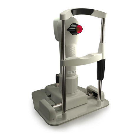
Figure 1. The E300 Instrument.

Intended Purpose
4
Medmont E300 Corneal Topographer
For the diagnosis, treatment or monitoring of a patient under medical
supervision there are three area definitions: Patient Environment,
Medically used room and Non-medically used room. Each area
demands different electrical safety requirements for your system.
Please make sure that your system is set up correctly in the right
environment.
When used in a Patient Environment, the PC and its Monitor (if
separate, refer to Figure 2) must be powered via a protective isolation
transformer, compliant to the governing medical standard IEC60601-
1 or UL2601/CSA22.2#601-1 for North America only. A hospital
grade power cord must be used to achieve reliable grounding. The
Isolation Transformer must be certified either cULus or cCSAus for
North America, or UL for US market or CSA for Canadian market or
meet National Electrical Regulations.
Standard E300 Accessories
USB Video Converter box
USB 2.0 cable
Calibration Object R 8mm with mounting screw
Standard Table Top
Chinrest
Instrument Cover
Accessory box including: 2 Rail covers, 4 mounting screws for
chinrest, 2 chinrest pins, 1 box chinrest paper, Caution label
(EN/IEC60950 equipment), Com port insulation plug, spare fuse
E300 USB Quick install guide
Medmont Studio Installation Software and calibration file on
USB key
Software license activation number
Optional System Accessories available from Medmont
DV2000 Diagnostic Video Imaging software module
Electric Table
Converter box upgrade kit
Reverse adaptor cable
Replacement slide rail replacement kit for E300, E300 W

Intended Purpose
Medmont E300 Corneal Topographer
5
Spare Parts
Calibration Ball PN: 0274-370
Com Port insulation plug PN: 0744
Main Cable Replacement Kit PN: 2097
Consumables
Chinrest Paper
models E300, E300W-pack 300 pc models E300
U, E300 USB - pack 300 pc
Cotton swabs
Tapered double headed on 150mm wooden sticks.
Cat No MG 8112-100 bag of 100

Intended Purpose
6
Medmont E300 Corneal Topographer
The E300 Software
The E300 Software is part of the Medmont Studio integrated software
environment. See the Medmont Studio documentation for help on installing
and using the Medmont Studio environment.
Software Conventions
When referring to menu selections, the notation Home >Patient > New
means click on the Home ribbon bar tab, then look for the Patient group on
the ribbon bar and click on the New icon. This format conforms to the Tab >
Group > Action system for identifying menu items in a ribbon bar menu
system.
Some keyboard shortcuts can be used when setting spin-box controls like the
one shown here. Use the numeric keys for direct entry, up/down arrows for
small steps, PgUp/PgDn keys for large steps,
and the Home/End keys to move to max/min of the currently selected number.

Warranty
Medmont E300 Corneal Topographer
7
3.Warranty
The E300 Corneal Topographer device has been manufactured with all due
care and subjected to stringent testing before leaving the factory. The
Topographer is guaranteed for 12 months from the date of purchase as
evidenced by the invoice. During this warranty period Medmont or an
authorised agent will repair or replace all defective parts free of charge. Such
repairs do not extend the warranty period. Replaced parts become the property
of Medmont. The warranty does not cover defects due to incorrect handling,
installation and setup, unauthorised modifications, non-compliance with the
requirements for computer hardware and associated mains powered
equipment as specified in the User Manual, loss of the license, loss of income,
or service and repair costs for components and associated equipment.
Warranty claims are the responsibility of the outlet where the device was
purchased.
The warranty and calibration is void, if the QA seal between camera and optics
housing is broken.

Important Facts
8
Medmont E300 Corneal Topographer
4.Important Facts
The E300 Corneal Topographer is a highly accurate measuring instrument. It
measures and maps the surface of the human cornea and represents the results
in various quantities and output forms that can be applied in various medical
applications. It combines these results with theoretical surface shapes to form
the basis for precise contact lens fitting.
Explanation of Symbols and Labels:
Caution - potentially hazardous situation which if not
avoided could result in minor or moderate personal
injury.
Warning - In event of user error or equipment fault
condition there may be a serious risk to health or life of
patients or operator, or product damage or loss may
occur.
Note – notice that additional attention should be paid to
use or maintenance to prevent misuse or unexpected
behaviour.
Attention, consult accompanying documents.
Alternating current.
USB – Universal Serial Bus
Compliance with the EC Directive 93/42 EEC and
RoHS2 Directive 2011/65/EU
North American compliance mark for US and Canada
The date below this symbol shows the year and month
of manufacturing.
Waste Electrical and Electronic Equipment Directive
(WEEE Directive) 2012/19/EU on waste electrical and
electronic equipment.
No disposal of goods in general waste.

Important Facts
Medmont E300 Corneal Topographer
9
Power Indicator on rear side of unit. The E300 is
powered if indicator is illuminated green, unpowered if
un-illuminated.
Warning: Remove Mains and USB Cord Before
Opening Enclosure!
WARNING: USA and Canada; Grounding reliability
can only be achieved to a receptacle marked
“HOSPITAL ONLY” or “HOSPITAL GRADE”
PLEASE REFER TO PRODUCT MANUAL
AVERTISSEMENT: USA et Canada, La fiabilité de la
mise à la masse de cet equipment ne peut être réalisé
que si celui-ci est connecté à une price marquée
“HÔSPITAL SUELMENT” ou “CLASSE HÔSPITAL”
VEUILLEZ VOUZ PRÉFÉRER AU MANUEL DU
PRODUIT
The patient environment comprises a 1.5m radius
around the area in which patient or some other person
can touch parts of the medical system intentionally or
unintentionally. This label is to be attached in a visible
position on any EN/IEC 60950 compliant equipment
used within the electro-medical system of the E300.
This label is found on the PC port insulation plugs.
These plugs are for RS232 and Network ports, and these
ports are to be covered if the PC is used within the
patient environment.
E300 Device Label (here shown for the USB variant) -
positioned at bottom of base next to cable exit.
Regulatory Information
This instrument complies with all applicable Regulatory requirements and
Safety Standards.

Important Facts
10
Medmont E300 Corneal Topographer
Classification
In accordance with IEC 60601-1 the E300 Corneal Topographer is classified:
Protection against electric shock
Class I
Protection against harmful ingress of water
Ordinary (no protection)
Mode of Operation
Continuous Operation
Clinical Results
This manual does not provide guidance on interpretation of clinical results.
The clinician must ensure that he or she has received appropriate medical
training in such interpretation. For this reason Medmont cannot be held
responsible for any misdiagnosis of results.
Accuracy and Calibration
The E300 is delivered to the end user quality tested, calibrated and as per
specifications. It is not the responsibility of Medmont to guarantee or police
the accuracy of this instrument after delivery. The E300 is delivered with a
calibrated and certified test object with an accuracy based on the national
standard. The customer can verify the accuracy of the instrument with the
calibration object provided. Medical Regulations require, that the functional
accuracy of equipment used for professional purposes be verified every two
years. This can be achieved by re-calibrating the test object. Medmont or their
authorised agents can provide this service in return for a fee. The E300 must
then be re-calibrated by the customer using the newly calibrated test object.
Radiation
The E300 emits radiation in the visual range for illumination in the distinct
wavelength 660nm (red LED cone illumination), 565nm (green LED fixation
target) and 430nm (blue LED profile illumination). The levels of intensity of
this illumination are less than 50 cd/m2, below any levels known to be
hazardous.
Electromagnetic Interference
Strong electromagnetic interference from unprotected devices or
portable and mobile RF communications equipment or mains
disturbances (voltage dips, transient surges) or electrostatic discharge
may affect the performance or results of the E300 USB Corneal
Topographer. Avoid using the device while such high interference is
present. The device is compliant with medical standard
EN/IEC60601-2.

Important Facts
Medmont E300 Corneal Topographer
11
Guidance and manufacturer’s declaration – electromagnetic immunity
The E300 Corneal Topographer is intended for use in the electromagnetic environment specified
below. The customer or the user of the E300 USB Corneal Topographershould assure that it is
used in such an environment.
IMMUNITY test
IEC 60601
test level
Compliance level
Electromagnetic
environment –
guidance
Electrostatic
discharge (ESD)
IEC 61000-4-2
6 kV contact
8 kV air
6 kV contact
8 kV air
Floors should be wood,
concrete or
ceramic tile. If floors are
covered with
synthetic material, the
relative humidity
should be at least 30 %.
Electrical fast
transient/burst
IEC 61000-4-4
2 kV for power
supply lines
1 kV for input/output
lines
2 kV for power
supply lines
1 kV for
input/output
lines
Mains power quality should
be that of a
typical commercial or
hospital
environment.
Surge
IEC 61000-4-5
1 kV line(s) to
line(s)
2 kV line(s) to earth
1 kV line(s) to
line(s)
2 kV line(s) to
earth
Mains power quality should
be that of a
typical commercial or
hospital
environment.
Voltage dips, short
interruptions and
voltage variations
on power supply
input lines
IEC 61000-4-11
<5 % UT
(>95 % dip in UT)
for 0,5 cycle
40 % UT
(60 % dip in UT)
for 5 cycles
70 % UT
(30 % dip in UT)
for 25 cycles
<5 % UT
(>95 % dip in UT)
for 5 s
<5 % UT
(>95 % dip in UT)
for 0,5 cycle
40 % UT
(60 % dip in UT)
for 5 cycles
70 % UT
(30 % dip in UT)
for 25 cycles
<5 % UT
(>95 % dip in UT)
for 5 s
Mains power quality should
be that of a
typical commercial or
hospital
environment. If the user of
the
E300 SUB Corneal
Topographerrequires
continued operation during
power
mains interruptions, it is
recommended
that the [ME EQUIPMENT or ME
SYSTEM]
be powered from an
uninterruptible
power supply or a battery.
Power frequency
(50/60 Hz)
magnetic field
IEC 61000-4-8
3 A/m
3 A/m
Power frequency magnetic
fields
should be at levels
characteristic of a
typical location in a typical
commercial
or hospital environment.
NOTE UT is the a.c. mains voltage prior to application of the test level.
The E300 USB Corneal Topographer is intended for use in the electromagnetic environment
specified below. The customer or the user of the E300 USB Corneal Topographer should assure
that it is used in such an environment.

Important Facts
12
Medmont E300 Corneal Topographer
Guidance and manufacturer’s declaration – electromagnetic immunity
IMMUNITY test
IEC 60601
test level
Compliance
level
Electromagnetic environment –guidance
Portable and mobile RF communications
equipment should be used no closer to any part of
E300 USB Corneal Topographer, including cables,
than the recommended separation distance
calculated from the equation applicable to the
frequency of the transmitter.
Recommended separation distance
𝒅 = 𝟏. 𝟐√𝑷
Conducted RF
IEC 61000-4-6
3 Vrms
150 kHz to
80 MHz
3V
𝒅 = 𝟏. 𝟐√𝑷 80 MHz to 800 MHz
\Radiated RF
IEC 61000-4-3
3 V/m
80 MHz to
2,5 GHz
3V/m
𝒅 = 𝟐. 𝟑√𝑷 800 MHz to 2,5 GHz
where P is the maximum output power rating of
the transmitter in watts (W) according to the
transmitter manufacturer and d is the
recommended separation distance in metres (m).
Field strengths from fixed RF transmitters, as
determined by an electromagnetic site survey, a
should be less than the compliance level in each
frequency range. b
Interference may occur in the vicinity of
equipment marked with the following symbol:
NOTE 1 At 80 MHz and 800 MHz, the higher frequency range applies.
NOTE 2 These guidelines may not apply in all situations. Electromagnetic propagation is affected
by absorption and reflection from structures, objects and people.
aField strengths from fixed transmitters, such as base stations for radio (cellular/cordless)
telephones and land mobile radios, amateur radio, AM and FM radio broadcast and TV broadcast
cannot be predicted theoretically with accuracy. To assess the electromagnetic environment due to
fixed RF transmitters, an electromagnetic site survey should be considered. If the measured field
strength in the location in which the E300 USB Corneal Topographeris used exceeds the
applicable RF compliance level above, the E300 USB Corneal Topographershould be observed to
verify normal operation. If abnormal performance is observed, additional measures may be
necessary, such as re-orienting or relocating the E300 USB Corneal Topographer.
bOver the frequency range 150 kHz to 80 MHz, field strengths should be less than 3 V/m.

Important Facts
Medmont E300 Corneal Topographer
13
Recommended separation distances between portable and mobile RF communications equipment
and the E300 USB Corneal Topographer
The E300 USB Corneal Topographer is intended for use in an electromagnetic environment in
which radiated RF disturbances are controlled. The customer or the user of the E300 USB Corneal
Topographercan help prevent electromagnetic interference by maintaining a minimum distance
between portable and mobile RF communications equipment (transmitters) and the E300 USB
Corneal Topographer as recommended below, according to the maximum output power of the
communications equipment.
Rated maximum
output power of
transmitter
W
Separation distance according to frequency of transmitter
m
150 kHz to 80 MHz
𝒅 = 𝟏. 𝟐√𝑷
80 MHz to 800 MHz
𝒅 = 𝟏. 𝟐√𝑷
800 MHz to 2,5 GHz
𝒅 = 𝟐. 𝟑√𝑷
0.01
0.12
0.12
0.23
0.1
0.38
0.38
0.73
1
1.2
1.2
2.3
10
3.8
3.8
7.3
100
12
12
23
For transmitters rated at a maximum output power not listed above, the recommended separation
distance d in metres (m) can be estimated using the equation applicable to the frequency of the
transmitter, where P is the maximum output power rating of the transmitter in watts (W) according
to the transmitter manufacturer.
NOTE 1 At 80 MHz and 800 MHz, the separation distance for the higher frequency range applies.
NOTE 2 These guidelines may not apply in all situations. Electromagnetic propagation is affected
by absorption and reflection from structures, objects and people.
Electromagnetic Emissions
This device does not emit harmful or undesired electromagnetic emissions.
The device is compliant with medical standard EN/IEC60601-2. MEDICAL
ELECTRICAL EQUIPMENT needs special precautions regarding EMC and
needs to be installed and put into service according to the EMC information
provided in the ACCOMPANYING DOCUMENTS.
If the E300 USB Corneal Topographer is used in a domestic establishment or
connected to the Mains Public Network following warning shall apply:
The use of ACCESSORIES, transducers and cables other than those
specified, with the exception of transducers and cables sold by the
MANUFACTURER as replacement parts for internal components,
may result in increased EMISSIONS or decreased IMMUNITY of
the E300 USB Corneal Topographer.

Important Facts
14
Medmont E300 Corneal Topographer
The E300 USB Corneal Topographer should not be used adjacent to
or stacked with other equipment and that if adjacent or stacked use is
necessary, the ME EQUIPMENT or ME SYSTEM should be
observed to verify normal operation in the configuration in which it
will be used.
Guidance and manufacturer’s declaration – electromagnetic emissions
The E300 Corneal Topographer is intended for use in the electromagnetic environment specified
below. The customer or the user of the E300 Corneal Topographer should assure that it is used
in such an environment.
Emissions test
Compliance
Electromagnetic environment –guidance
RF emissions
CISPR 11
Group 1
The E300 Corneal Topographer uses RF energy only
for its internal function. Therefore, its RF emissions are
very low and are not likely to cause any interference in
nearby electronic equipment.
RF emissions
CISPR 11
Class B
The E300 Corneal Topographer is suitable for use in all
establishments, including domestic establishments and
those directly connected to the public low-voltage
power supply network that supplies buildings used for
domestic purposes.
Harmonic emissions
IEC 61000-3-2
Class A
Voltage fluctuations/
flicker emissions
IEC 61000-3-3
Complies
Electromagnetic Compatibility and Emissions
This instrument conforms to the EMC Standard IEC 60601-1-2. The device
emits no harmful or undesired electromagnetic emissions.
Interference
Strong electromagnetic interference from other unprotected devices may
affect the performance or results of the E300. If the use of such devices with
high electromagnetic emissions cannot be avoided, do not use the E300 and
the device simultaneously.
Side effects
No undesired side effects to patient or clinician or other persons are known
when using this instrument under normal conditions and for the intended
purpose.
Electrical safety of medical electrical system
All the equipment connected of the E300 topographer shall be certified to
EN/IEC60950. It must be powered by an isolation transformer compliant to
the medical standard EN/IEC 60601-1, UL2601 or CSA22.2#601-1 (see
Standard E300 Accessories on page 4).
Other manuals for E300
1
Table of contents
Other Medmont Medical Equipment manuals
Popular Medical Equipment manuals by other brands

diagenode
diagenode Bioruptor user manual
Haag-Streit
Haag-Streit BQ 900 manual
SystemRoMedic
SystemRoMedic WendyLett4Way manual
Sensa Core
Sensa Core Hemo Spark user manual

nCounters
nCounters DataQ Operation manual
Shenzhen Roundwhale Technology Co., LTD.
Shenzhen Roundwhale Technology Co., LTD. R-C4D instruction manual

