Medrad Veris 8600 User manual

Page i
VerisTM 8600
Vital Signs Monitor
Operation Manual
3010796 Revision 0
Date 10/04
PRELIMINARY

Page ii
VerisTM 8600
Operation Manual
Copyright 2004, MEDRAD Inc. All rights reserved.
Reproduction of this manual is strictly prohibited
without express written consent of MEDRAD, Inc.
For more information about MEDRAD products
and services, please visit www.medrad.com

Page iii
Contents
Contents................................................................................................................iii
In Case of Emergency Contact.............................................................................xi
MEDRAD Subsidiaries.....................................................................................xi
International Offices.........................................................................................xi
Symbols ..............................................................................................................xiii
Regulatory Symbols....................................................................................... xiii
Safety Symbols..............................................................................................xiii
System Symbols............................................................................................xiv
Port Symbols .................................................................................................xiv
Miscellaneous Symbols.................................................................................xiv
Safety...................................................................................................................xv
Definitions.......................................................................................................xv
Warnings.........................................................................................................xv
Cautions........................................................................................................xvii
Introduction .........................................................................................................xxi
Description.....................................................................................................xxi
Intended Use .................................................................................................xxi
Clinical Use................................................................................................... xxii
Section 1 - Panel Features
Front Panel ................................................................................................................... 1-1
Menu Knob......................................................................................................... 1-2
Color Display......................................................................................................1-2
Water Trap and Gas Sampling Connection .......................................................1-2
Left Side Panel (Main Monitor) .....................................................................................1-3
Communication Port (Main Monitor)............................................................................. 1-4
Main Monitor Base Connections...................................................................................1-5
Chassis Ground ................................................................................................. 1-5
DC Connection................................................................................................... 1-5
Exhaust Port....................................................................................................... 1-5
Air Intake Port .................................................................................................... 1-5
Remote Display.................................................................................................. 1-6
Printer ...........................................................................................................................1-8
Accessory Tray............................................................................................................. 1-8
Veris 8600 Configurations............................................................................................. 1-9
Section 2 - Monitor Setup
Battery Power ............................................................................................................... 2-1
Charging the Battery..........................................................................................2-1
Battery Indicators............................................................................................... 2-2
System Start and Auto-calibration ................................................................................ 2-3
Sensor and Probe Messages............................................................................. 2-4
Gas Calibration .................................................................................................. 2-4
Screen Display and Interface........................................................................................ 2-5
Waveform Slots.................................................................................................. 2-6
Numerical Parameter Boxes.............................................................................. 2-9
Main Menu ....................................................................................................... 2-11
Alarm and Message Areas...............................................................................2-12
System Status Box........................................................................................... 2-12
Patient Information and Clock.......................................................................... 2-12
Keypad........................................................................................................................ 2-13
Softkey Functions (Main Menu)..................................................................................2-14
Changing Settings............................................................................................ 2-14
Saved Setting Profiles......................................................................................2-15

Page iv
MEDRAD
Veris
8600
ALARMS Softkey.........................................................................................................2-16
Primary ALARMS Window................................................................................2-17
Invasive Blood Pressure Alarm Settings ..........................................................2-18
Agent Gas Alarms ............................................................................................2-19
PARAMS Softkey (Physiological Parameters)............................................................2-21
Primary PARAMS Window...............................................................................2-21
SpO2, Respiration, Temperature Menu............................................................2-24
Gas Settings.....................................................................................................2-25
DISPLAY Softkey........................................................................................................2-27
Waveform Description......................................................................................2-27
Double Height Slots..........................................................................................2-28
Cascaded Slots ................................................................................................2-29
Gain and Sweep...............................................................................................2-30
ADM/DIS Softkey (Admit/Discharge)...........................................................................2-31
Admitting and Discharging Patients..................................................................2-31
Adult/Pediatric/Neonatal (Patient Size) ............................................................2-32
Patient Information ...........................................................................................2-32
Procedure for Admitting a Patient.....................................................................2-32
Procedure for Discharging a Patient.................................................................2-33
CONFIG Softkey (System Configuration)....................................................................2-34
Password Protection.........................................................................................2-35
Date Format......................................................................................................2-35
Time/Date Setting.............................................................................................2-35
Freeze Timeout ................................................................................................2-35
Standby Timeout ..............................................................................................2-35
Standby Tone...................................................................................................2-35
Alarm Tone Warning.........................................................................................2-35
Print Device......................................................................................................2-35
Language Settings............................................................................................2-36
PRINT Softkey.............................................................................................................2-37
Default Settings...........................................................................................................2-38
Factory Defaults ...............................................................................................2-38
Section 3 - Alarms and Messages
Alarm Description..........................................................................................................3-1
Remote Display Alarms......................................................................................3-1
Audible Alarms ...................................................................................................3-1
Visible Alarms.....................................................................................................3-2
Waveforms Frozen.............................................................................................3-2
Alert Icons...........................................................................................................3-3
Special Alarm Conditions..............................................................................................3-3
Alarms at Start Up..............................................................................................3-3
Alarm Silence .....................................................................................................3-3
Alarms tone warning (Warning Tone).................................................................3-4
Alarm Volume.....................................................................................................3-4
Minimum Volume Auto-Reset.............................................................................3-4
Standby Mode ....................................................................................................3-5
Agent Standby Mode..........................................................................................3-5
Standby Mode Timeout ......................................................................................3-5
SpO2Low Limit Auto-Reset................................................................................3-5
SpO2Low Limit Off Alarm ..................................................................................3-5
Triggering an Alarm.......................................................................................................3-6
Alarms Testing ..............................................................................................................3-6

Page v
Contents
Alarm Message List ......................................................................................................3-7
Shared Source Alarms....................................................................................... 3-7
ECG Alarms....................................................................................................... 3-7
SpO2Alarms......................................................................................................3-7
Temperature Alarms .......................................................................................... 3-8
NIBP Alarms....................................................................................................... 3-9
IBP Alarms....................................................................................................... 3-10
Capnometry (CO2) Alarms and Messages....................................................... 3-11
Agent Gas Alarms and Messages.................................................................... 3-11
Oxygen Monitoring (O2) Alarms....................................................................... 3-13
System Alerts.............................................................................................................. 3-14
Section 4 - Trends
Description.................................................................................................................... 4-1
Trend Interval..................................................................................................... 4-1
Capacity............................................................................................................. 4-1
Trend Screen Update......................................................................................... 4-1
Trend Setup .................................................................................................................. 4-2
Graphical Trends ..........................................................................................................4-4
Scrolling the Graph ............................................................................................4-4
Interruption Due to Power Cycling or Standby Mode.........................................4-4
Graphical Trend Display.....................................................................................4-5
Tabular Trends.............................................................................................................. 4-6
Tabular Trend Markers....................................................................................... 4-6
Trend Messages ................................................................................................ 4-6
Data Format....................................................................................................... 4-7
Clearing the Memory................................................................................................... 4-10
Section 5 - ECG
Theory of Operation......................................................................................................5-1
Heart Rate..........................................................................................................5-1
ECG Measurement ............................................................................................ 5-1
ECG module....................................................................................................... 5-2
Gating Signals.................................................................................................... 5-3
ECG Monitoring (Electrocardiogram)............................................................................ 5-4
Protection........................................................................................................... 5-6
ECG Performance.............................................................................................. 5-6
Electrode Selection ............................................................................................ 5-6
ECG Module Interface .................................................................................................. 5-7
ECG Module Ports And Switches ...................................................................... 5-7
Battery Condition................................................................................................ 5-8
Charging the Battery..........................................................................................5-9
ECG Monitoring .......................................................................................................... 5-11
Patient Preparation .......................................................................................... 5-11
Lead Placement............................................................................................... 5-12
Connecting Patient to the Monitor.................................................................... 5-14
Completion of ECG Monitoring ........................................................................ 5-15
ECG Auto Lead Switching .......................................................................................... 5-16
Primary Lead....................................................................................................5-16
Alternate Lead Priority......................................................................................5-17
Gating Interface .......................................................................................................... 5-18

Page vi
MEDRAD
Veris
8600
Section 6 - NIBP
Theory of Operation ......................................................................................................6-1
Heart Rate..........................................................................................................6-1
Comfort Cuff™ Technology................................................................................6-1
Description of NIBP Measurement.....................................................................6-1
NIBP Clinical Testing and Accuracy...................................................................6-1
Cuff Inflation and Pressure Protection................................................................6-2
NIBP Monitoring............................................................................................................6-3
Selecting Cuffs and Hoses............................................................................................6-5
Placing the NIBP Cuff....................................................................................................6-6
Procedure......................................................................................................................6-7
Taking NIBP Measurements .........................................................................................6-8
Section 7 - SpO2
Theory of Operation ......................................................................................................7-1
Heart Rate..........................................................................................................7-1
Definition.............................................................................................................7-1
DOX™ Digital Oximetry......................................................................................7-1
Method................................................................................................................7-1
SpO2Clinical Testing and Accuracy...................................................................7-2
Gating Signals....................................................................................................7-2
SpO2Monitoring Procedures (Pulse Oximetry).............................................................7-3
Attaching the Probe to the Monitor................................................................................7-4
Attaching the Probe to the Patient.................................................................................7-4
Finger Probe Application for Adults....................................................................7-6
Neonate Probe Placement .................................................................................7-7
SpO2Peripheral Gating ..............................................................................................7-10
Section 8 - IBP
Theory of Operation ......................................................................................................8-1
Heart Rate..........................................................................................................8-1
Method of Measurement.....................................................................................8-1
IBP Clinical Testing and Accuracy......................................................................8-1
IBP Monitoring...............................................................................................................8-2
Invasive Blood Pressure Transducers and Interface Cables ........................................8-3
IBP Interface Cable ............................................................................................8-3
IBP Monitoring Procedure.............................................................................................8-5
IBP Safety...........................................................................................................8-6
Setup and User Calibration ................................................................................8-6
Zero Calibration (Quick) .....................................................................................8-8
Clinical Use and Arterial Waveforms..................................................................8-9
Section 9 - Temperature
Theory of Operation ......................................................................................................9-1
Temperature Monitoring Procedures.............................................................................9-2
Directions for Use with Skin Surface Probe ..................................................................9-4
Preparing the Equipment....................................................................................9-4
Attaching the Temperature Probe to the Patient................................................9-4

Page vii
Contents
Section 10 - Anesthetic Agents
Theory of Operations .................................................................................................. 10-1
Integrated CO2 and Agent Gas Detector ......................................................... 10-1
Agent Gas Measurement.................................................................................10-1
Gas Monitoring Procedures ........................................................................................ 10-2
Sampling Circuit Connections.......................................................................... 10-2
Gas Monitoring Safety...................................................................................... 10-3
Water Trap ....................................................................................................... 10-4
Sampling Devices ............................................................................................ 10-5
Intubated Patients ............................................................................................ 10-5
Calibration and Startup .................................................................................... 10-6
Procedure for Gas Monitoring.......................................................................... 10-7
Occlusions........................................................................................................10-7
Anesthetic Gas Exhaust Recovery................................................................... 10-7
Section 11 - CO2, O2, and N2O
Theory of Operation....................................................................................................11-1
Respiration....................................................................................................... 11-1
Capnometry (Measurement of CO2)................................................................ 11-1
Measuring Oxygen (O2)...................................................................................11-2
CO2Monitoring Procedure.......................................................................................... 11-4
O2Monitoring Procedures .......................................................................................... 11-5
Interfering Gasses for O2.................................................................................11-5
N2O Monitoring........................................................................................................... 11-5
Section 12 - Printing and Data Ports
Description.................................................................................................................. 12-1
Snapshot Size.................................................................................................. 12-1
History Size......................................................................................................12-1
Safety.......................................................................................................................... 12-1
Print Modes................................................................................................................. 12-2
Demand Print................................................................................................... 12-2
Continuous Print............................................................................................... 12-2
Alarm Print ....................................................................................................... 12-2
BP Print............................................................................................................ 12-2
Interval Print..................................................................................................... 12-2
Freeze Print......................................................................................................12-2
Trend Print ....................................................................................................... 12-3
Print Formats .............................................................................................................. 12-4
Tabular Printing................................................................................................ 12-4
Graphical Printing............................................................................................. 12-4
Changing Printer Paper .............................................................................................. 12-7
Data Output Ports....................................................................................................... 12-9
COM1 Port....................................................................................................... 12-9
COM2 Port..................................................................................................... 12-11
Video Port ................................................................................................................. 12-11
CSV Data Format......................................................................................................12-12

Page viii
MEDRAD
Veris
8600
Appendix A: Maintenance
Cleaning and Disinfecting............................................................................................. A-1
Pulse Oximeter Sensors.................................................................................... A-2
Blood Pressure Cuffs......................................................................................... A-2
Temperature...................................................................................................... A-3
Accidental Wetting........................................................................................................ A-4
Annual Safety Tests..................................................................................................... A-5
System Testing.................................................................................................. A-5
Service Checks.................................................................................................. A-5
Maintenance Schedule................................................................................................. A-6
Long-Term Storage...................................................................................................... A-7
Disposal........................................................................................................................A-7
Appendix B: Unit and Configuration Defaults
Restoring the Unit Default Profile................................................................................. B-1
Default Settings............................................................................................................ B-1
Unit Default Settings.......................................................................................... B-1
Configuration Default Settings........................................................................... B-3
Configuration Settings for Unit Defaults....................................................................... B-5
PARAMS Menu Settings ................................................................................... B-5
PRINT Menu Settings........................................................................................ B-6
DISPLAY Menu Settings ................................................................................... B-6
ALARMS Menu Settings.................................................................................... B-7
Other Alarm Settings....................................................................................... B-11
Appendix C: Specifications
ECG..............................................................................................................................C-1
ECG System......................................................................................................C-1
ECG Module......................................................................................................C-1
Leadset..............................................................................................................C-1
ECG Module Charger........................................................................................C-2
SpO2............................................................................................................................C-2
Heart Rate....................................................................................................................C-2
Gating...........................................................................................................................C-3
Temperature.................................................................................................................C-3
NIBP.............................................................................................................................C-3
Invasive Blood Pressure...............................................................................................C-4
Transducer ........................................................................................................C-4
Capnometry (CO2) .......................................................................................................C-4
CO2Respiration...........................................................................................................C-4
Halogenated Agents.....................................................................................................C-5
Nitrous Oxide (N2O).....................................................................................................C-6
Oxygen Monitoring (O2) ...............................................................................................C-6
Pneumatics...................................................................................................................C-6
Alarms..........................................................................................................................C-6
Trend Reports ..............................................................................................................C-7
Printer (Remote Display only) ......................................................................................C-7
Controls........................................................................................................................C-7
System Outputs (Remote Display Only).......................................................................C-7
Environmental ..............................................................................................................C-7
Mechanical/Electrical....................................................................................................C-8
Remote Display.................................................................................................C-8
Main Monitor......................................................................................................C-8

Page ix
Contents
Appendix D: Accessories
ECG Accessories..........................................................................................................D-1
ECG Module.......................................................................................................D-1
ECG Electrode Accessories...............................................................................D-1
ECG Gating Accessories ...................................................................................D-1
SpO2Accessories.........................................................................................................D-1
SpO2Probes......................................................................................................D-1
SpO2Peripheral Gating Accessories.................................................................D-1
NIBP Accessories.........................................................................................................D-2
Reusable Cuffs...................................................................................................D-2
Disposable Cuffs................................................................................................D-2
IBP Accessories............................................................................................................D-2
Temperature Accessories.............................................................................................D-2
Agent Accessories ........................................................................................................D-2
Miscellaneous Accessories...........................................................................................D-3
Publications...................................................................................................................D-3
Operation Manuals.............................................................................................D-3
Help Cards.........................................................................................................D-3
Installation and Service......................................................................................D-3
Appendix E: Troubleshooting
General Troubleshooting ..............................................................................................E-1
Troubleshooting Table..................................................................................................E-1
Appendix F: IBP Transducer Specifications
IBP Specifications..............................................................................................F-1
Transducer Specifications..................................................................................F-1
Transducer Cables.............................................................................................F-1
Compliance........................................................................................................F-1
Defibrillation Protection......................................................................................F-1
High Frequency Interference..............................................................................F-2
Appendix G: Wireless Communication
Wireless Network Communication Interface................................................................ G-1
Operation..................................................................................................................... G-1
Appendix H: Battery and Fuse Specifications
Battery Specifications ...................................................................................................H-1
Main Monitor Batteries.......................................................................................H-1
Fuse Specifications.......................................................................................................H-2
Remote Display Fuses.......................................................................................H-2
Main Monitor Fuses............................................................................................H-2
Power Supply Fuses..........................................................................................H-2
Fuse Removal/Replacement.........................................................................................H-3
Remote Display..................................................................................................H-3
Power Supply.....................................................................................................H-4

This page intentionally left blank.

Page xi
In Case of Emergency
Contact
MEDRAD, Inc. Corporate Office MEDRAD, Inc. Service Repair
One Medrad Drive One Medrad Drive
Indianola, PA 15051-0780 USA Indianola, PA 15051-0780 USA
Telephone: 1 (412) 767-2400 Telephone: 1 (412) 767-2400
FAX: 1 (412) 767-4128 FAX: 1 (412) 767-4126
OTHER: 1 (800) 633-7231 OTHER: 1 (800) 633-7237
MEDRAD Subsidiaries
Imaxeon Pty. Ltd.
Rydalmere Metro Centre (Alternate address:)
Unit 2, 38-46 South Street P.O. Box 150
Rydalmere NSW 2116 Rydalmere BC
Australia NSW 1701
Telephone: +61 2 8845 4999 Sydney, Australia
FAX: +61 2 8845 4998
MEDRAD Europe B.V. Nihon MEDRAD K.K.
P.O. Box 205 9F Central Shin-Osaka Bldg.
6190 AE Beek 4-5-36, Miyahara
The Netherlands Yodogawa-ku
Telephone: +31 (0) 43-3585600 Osaka 532-0003, Japan
FAX: +31 (0) 43-3656598 Telephone: +81 (0) 6-6350-0680
(Visiting MEBV address:) FAX: +81 (0) 6-6398-0670
Horsterweg 24
6199 AC Maastricht Airport
The Netherlands
International Offices
MEDRAD do Brasil ltda.Mediwest Denmark ApS
Av. Fagundes Filho, 191 - Naverland 2
conjuntos 51 a 54 e 57 2600 Glostrup
Ed. Houston Office Center Denmark
Vila Monte Alegre Telephone: +45 38-16 16 16
04304-000 - São Paulo - SP FAX: +45 38-16 16 46
Telephone: +(11) 5079-6500
FAX: +(11) 5584-8951
MEDRAD Middle East & Africa
92 Al Lasilky Street
New Maadi Cairo
Egypt
E-mail: Medrad_ME&A@medrad.com
(If contacting Andre directly, please
phone or fax)
+00.20.2.754.88.29

Page xii
MEDRAD
Veris
8600
MEDRAD France S.a.r.l. MEDRAD, Inc. (Asia)
8, rue des Pyrénées — Silic 514 200 Jalan Sultan #09-01
Wissous Textile Centre
F-94623 Rungis Singapore 199018
France Telephone: +(65) 6 292 5357
Telephone: +33 (0) 1.46.86.98.84 FAX: +(65) 6 292 7276
FAX: +33 (0) 1.46.86.98.83
MEDRAD Italia S.r.l. MEDRAD Medizinische Systeme
GmbH
Via Togliatti, 111 Industriestraße 2b
27051 Cava Manara (PV) 97332 Volkach
Italy Germany
Telephone: +39 (0) 382 552882 Telephone: +49 (0) 9381/80 36 80
FAX: +39 (0) 382 552876 FAX: +49 (0) 9381/80 36 85
MEDRAD Mexicana S. de Mediwest Norway AS
R.L. de C.V.
Leibnitz, 204 Aslakveien 14A
Col. Anzures Del. Miguel Hidalgo NO-075
CP. 11590 Mexico City 3
Mexico D.F. 16018 Oslo, Norway
Telephone: +52 (555) 250-6575 Telephone: +47 (0) 22-06 57 10
FAX: +52 (555) 250-9762 FAX: +47 (0) 22-06 57 15
Mediwest Scandinavia AB MEDRAD UK Ltd.
Lona Knapes gata 5, plan 2 25 Lancaster Way Business Park
S-421 32 Västra Frölunda Witchford, Ely
Sweden Cambridgeshire
Telephone: +46 (0) 31-74 82 88 0 CB6 3NW
FAX: +46 (0) 31-74 82 99 9 Telephone: +44 (0) 1353-645024
FAX: +44 (0) 1353-645037

Page xiii
Symbols
Symbol Definition
Regulatory Symbols
European Community Mark
ETL Mark
FCC (US Federal Communications Commission)
Mark
Safety Symbols
ATTENTION! Refer to Operation Manual for
Information
Shock Hazard
Type CF Equipment, defib proof
Indicates no protection against ingress of water
(remote display)
Identifies the degree of protection against fluid as
drip-proof (main monitor)
Identifies the degree of protection against fluid as
drip-proof (power supply)
Equipotential Terminal
Protective Earth
Indicates the MR magnet and power
Indicates distance between MR magnet and monitor
Indicates the presence of a battery
Recycle batteries following hospital protocols and
local environmental regulations.
Do not incinerate! Keep away from fire or other
sources of extreme heat.
IPX0
IPX1
IPX2

Page xiv
MEDRAD
Veris
8600
Symbol Definition
Dispose of batteries properly in accordance with
hospital and local regulations.
Risk of electrical shock! Do not remove cover.
Refer servicing to qualified personnel.
System Symbols
Fuse
Alternating Current (AC)
Direct Current (DC)
Wireless Device
Port Symbols
Signal Input
Signal Output
Digital Output
Air Intake
Scavenging Port
Communication Port
Video Out
IOIOI

Page xv
Symbols
Miscellaneous Symbols
Symbol Definition
Technical Support Phone Number
Manufacturing Contact
Serial Number
Part Reference Number
Place this side against the skin (Blood Pressure Cuff)
Placement of the cuff over the brachial artery.
Single use device only. Do not reuse.
SN
REF
2

Page xvi
Safety
Definitions
Definitions for Warning, Caution, and Note symbols:
Designates a possible dangerous situation.
Non-observance may lead to death or the most
severe injuries.
Designates a possible dangerous situation.
Non-observance may lead to minor injuries or
damage to the product.
NOTE: Indicates that important information follows, a tip that can help
you recover from an error, or point you to related details in the
manual.
Warnings
• Read this manual entirely before using the monitor.
• Inspect For Damage! User should inspect the system for signs
of damage. Do not use the system if failure is evident or
suspected.
• Possible burn hazard! Do not coil cables inside the MR scanner.
• Possible explosion hazard! Do not use the monitor in the
presence of flammable anesthetics. The equipment is not
suitable for use in the presence of a flammable anesthetic
mixture with air or with oxygen or Nitrous Oxide.
• Possible explosion hazard! Do not use the monitor in the
presence of gas mixtures which may be flammable.
• Cables, tubing, and lead wires may present a risk of
entanglement or strangulation! Verify safe and proper
positioning of these items at all times.
• Unapproved modifications to the monitor may cause unexpected
results and present a hazard to the patient.
• Risk of electrical shock! Do not remove cover. Refer servicing to
qualified personnel.
• All cords must have hospital grade plugs and be plugged into
hospital grade outlets. (The electrical installation of the relevant
room must comply with NFPA 70: National Electric Code or
NFPA 99: Standard for Health Care Facilities. Outside the
United States, the relevant room must comply with all electrical
installation regulations mandated by the local and regional
bodies of government).
• Do not bring tools containing ferrous material into the magnet
room. Risk of serious injury and/or damage to equipment can
occur.
WARNING
!!
CAUTION
!!
WARNING
!!

Page xvii
Safety
• Do not route gating cables near or within the scanning volume.
• Apply brakes to prevent movement.
• Do not re-use accessories labeled as single use. Risk of patient
contamination may occur.
• Improper disposal of batteries may result in explosion, leakage,
or personal injury. Do not open batteries. Do not dispose of
batteries in a fire. Follow all local regulations concerning the
disposal of spent Lead-acid and Lithium-Ion batteries or contact
MEDRAD for assistance.
• Connect only MEDRAD approved three-lead or five-lead ECG
cables from the patient to the ECG module. Do not connect any
other signal source to the ECG module.
• There is no defibrillator synchronization output on the Veris
monitor. Make no connections between the Veris and a
defibrillator.
• Leakage currents may increase if other equipment is
interconnected to the patient. The increased leakage currents
may present a hazard to the patient.
• PACEMAKER PATIENTS: This device does not include
pacemaker spike rejection capability. Heart rate readouts
derived from the ECG patient connections are likely to display
erroneous high or erratic rates when a pacemaker is in use.
Keep pacemaker patients under close surveillance. For
pacemaker patients it may be advisable to select the SpO2
function as the primary heart rate source.
• High Frequency (HF) surgical equipment may affect ECG
operation. The system is not designed to operate in the
presence of ESU interference. The patient may be burned.
Patient burns can also result from defective HF surgical
equipment neutral electrode connection.
• The heart rate calculated by the monitor may be affected by
cardiac arrhythmia.
• Do not take the remote display or the ECG module battery
charger into the MR scanner room. These contain ferromagnetic
material and can be strongly attracted to the magnet causing a
safety hazard.
• Do not use with an open MRI. Use of the monitor in an open
MRI may result in erratic or unavailable monitoring.
• Do not stand or sit on monitor accessories tray. Possible injury
can result from falling.
WARNING
!!

Page xviii
MEDRAD
Veris
8600
• Do not lift the monitoring system by the tray. Possible injury can
result from heavy weight.
• U.S. Federal law restricts this device to sale by or on the order
of a physician.
Cautions
• Use only accessories designated for use with this monitor. Use
of accessories not designated for use with the Veris monitor can
cause inaccurate measurements and/or a safety hazard for the
patient.
• Equipment accuracy may be affected at extreme temperatures.
• Do not store equipment at extreme temperature. Temperatures
exceeding specified storage temperatures could damage the
system.
• Avoid routing the DC cable through the magnet room door.
Possible damage can occur to the DC cable and/or the scanner
room door.
• Do not press on the keys with sharp or hard objects. This could
damage the keys. Use only your fingertips to press on the keys.
• Changes or modifications not expressly approved by MEDRAD,
Inc., may void the user's authority to operate the equipment and
may also void the warranty.
• Do not use the monitor in the path of a Linear Accelerator or
Positron Emission Tomography (PET) scanner beam. This could
result in inaccurate physiologic parameters or waveforms.
• Transporting the monitor in a mobile scanner trailer can lead to
damage from shock, vibration, or extreme temperatures.
• Do not allow the conductive parts of the patient electrodes to
contact other conductive parts, including ground (earth).
• Do not tip the monitor. Possible injury can result from falling.
• Do not stand on power supply enclosure. Injury from tripping or
falling can occur.
• Do not stand on the base. Possible injury can result from falling.
• Do not pinch cables between the table and the bore. This can
damage the cables.
• Do not roll the monitor over or step on cables. This can damage
the cables.
WARNING
!!
CAUTION
!!
Page xix
Safety
• Do not bend fiber optic cables too tightly. Follow cable
manufacturers specifications for bend allowance.
• If a probe falls on the floor or into liquid, clean the probe
following proper cleaning methods. If the probe is not properly
cleaned, inaccurate physiologic parameters or waveforms may
result.
• Do not place more than 40 pounds (18 kg) on the tray.
Leakage Current
The monitor complies with leakage current limits required by medical
safety standards for patient-connected devices. The Veris monitor
conforms to EN 60601-1 standards. A hazard caused by the
summation of leakage currents is possible, when several pieces of
equipment are interconnected.
Voltage Fluctuations
When operated in the line voltage range specified in this manual any
minor fluctuations will have a negligible effect. Very low line voltage
will cause the monitor to revert to battery power. Very high line
voltage may cause damage to the charger circuits. The monitor is
designed with circuitry that will turn the unit off before spurious
readings can be caused by a low battery condition.
Equipotential Ground
Health care providers and patients are subject to dangerous,
uncontrollable compensating currents for electrical equipment.
These currents are due to the potential differences between
connected equipment and touchable conducting parts as found in
medical rooms.
The safety solution to the problem is accomplished with consistent
equipotential bonding. Medical equipment is fitted with connecting
leads made up with angled sockets to the equipotential bonding
network in medical rooms.
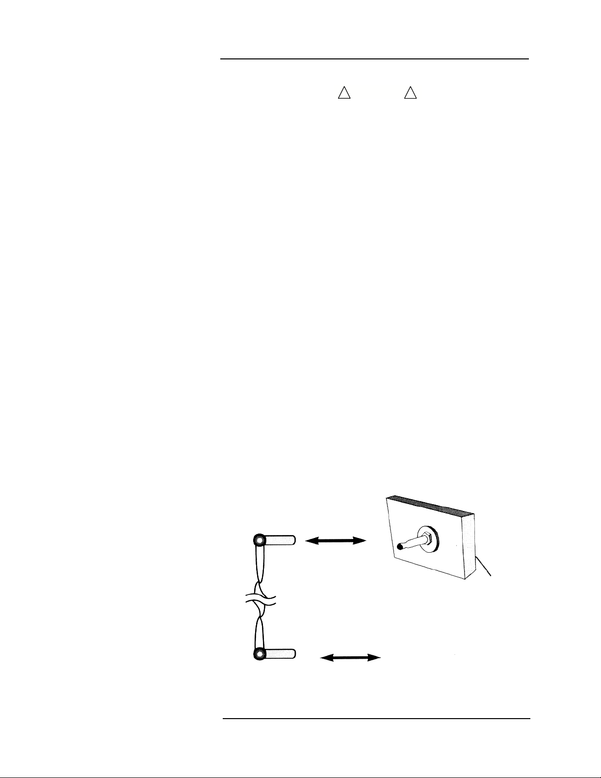
CAUTION
!!
Connection Lead
(Socket)
Equipotential
Connector
Equipotential
Terminal
Main
Body
Earth Ground

Page xx
MEDRAD
Veris
8600
Software Error Related
Hazard Mediation
MEDRAD, Inc., has quality control practices and procedures in place
to review potential hazards as they relate to software. The monitor
utilizes a four-digit year for all date, time, and leap year calculations.
Potential Interference
This device has been tested to 60601-1-2 specified levels for
emissions of and immunity to electrical interference. External
disturbances which exceed these levels, such as motor driven tools,
may cause operational issues with this device. Other devices which
are sensitive to a lower level of emissions than those allowed by
IEC 60601-1-2 2nd Edition may experience operational issues when
used in proximity to this device.
MAGNETIC FIELDS
Always position the Veris Base, Base Plus, and Cardiac monitors at
or outside the 2000 Gauss line. Always position the Veris Anesthesia
monitor at or outside of the 500 Gauss line. This monitor is designed
specifically for MR compatibility and is 1.5 and 3T compatible. It will
not cause interference with MRI image quality, nor will its
performance be affected by the magnet field.
The "T" wave may become excessively large or inverted with the
patient in the magnetic field. This effect is due to hemodynamic flow
induced voltage and may interfere with QRS detection. Try other
leads and/or electrode placements for best results.
CONDUCTED TRANSIENTS
The monitor conforms with IEC 1000-4-4, and IEC 1000-4-5 for
conducted transients, and will operate with negligible adverse effects.
X-RAY, CT, ULTRASOUND, AND/OR NUCLEAR MEDICINE
The monitor will operate with negligible adverse effects in these
environments. However, the monitor should not be placed directly in
the radiated beam, which could damage the internal electronics of the
monitor.
OTHER INTERFERENCE
There is a negligible adverse effect to the monitor from infrared
energy and defibrillation.
Use of Anesthetics
Do not use this device in conjunction with flammable anesthetics
such as cyclopropane and ether. The monitor can sample from pure
oxygen environments, but the monitor itself should never be placed
inside an oxygen rich environment, such as an oxygen tent or gas
containment apparatus. Proper anesthetic gas waste recovery should
be used.
Biocompatibility
All patient-contact or user-contact materials in this monitor and it's
accessories have passed ISO 10993-5, -10, & -11 biocompatibility
tests or have been in use in clinical environments in large numbers
over an extended period of time predating these standards.
Table of contents


