MegaSquirt DBWX2 User manual

Users manual
DBWX2 Controller
Not For Release (BETA)

Table of contents
1. Introduction
2. I/O and pinout
3. Wiring
a. Crimping the connector pins
b. Assembling the connector
4. Wiring diagrams
a. Power and CAN-bus
b. Accelerator pedal
c. Throttlebody
5. Updating the controller
6. Understanding fault codes
a. ARM fault codes
b. AVR fault codes
7. PID Settings
a. Operating modes
b. Throttlebody specific settings
8. Configuring fault output
9. Step by step initial configuration guide
a. Setting up DBW throttle to MegaSquirt 3
Trademark Legal Notice. All product names, trademarks and registered trademarks are property
of their respective owners. All company, product and service names used in this document are
for identification purposes only. Use of these names,trademarks and brands does not imply
endorsement.
1

Introduction
DBWX2 controller
Features include 2 independent channels for drive by wire throttles. Both channels have
independent PID controller that is user configurable.
Safety is handled by using dual cpus. The redundant cpu architecture makes the controller one of
the safest in the industry. Both cpus monitor the pedal and throttle butterfly positions
independently and will disable the throttle if a malfunction in the system is detected.
2

I/O and pinout
The controller has six 0-5V analog inputs for pedal and drive by wire throttle body position
sensors. These inputs are protected from short to ground and +12V.
The controller has four 5V reference voltage outputs to be used as pedal and dbw position
sensor reference voltage. These outputs are protected from short to ground.
Two full bridge outputs to be used to drive the brushed DC motors in DBW throttlebodies. These
outputs are protected from short to ground and +12V.
Gray connector
1:DBW1
motor -
2: DBW1
motor +
3: DBW1 ref
5v out
4: DBW2 ref
5v out
5: DBW2
motor -
6: DBW2
motor +
7: DBW1 ref
gnd
8: DBW1
main sense
in
9: DBW1
secondary
sense in
10: DBW2 ref
gnd
11: DBW2
main sense
12: DBW2
secondary
sense
Black connector
1: +12V IN
2: +12V in
3: Pedal main
5v out
4: Pedal main
sense in
5: CAN-L
6: CAN-H
7: GND IN
8: GND IN
9: Pedal
secondary 5v
out
10: Pedal
secondary
sense in
11: Pedal
reference
gnd
12: DBW
fault output
3

Wiring
Steps to take for a good install with custom wiring
1. Make sure that you have the proper crimping tools
2. Use proper gauge wire
Connector and pin part numbers:
Molex MX150 Black connector: 33472-1201
Molex MX150 Gray connector: 33472-1202
Molex MX150 Pins for 22AWG: 33012-2003
Molex MX150 Pins for 18-20AWG: 33012-2002
Molex MX150 Pins for 14-16AWG: 33012-2001
Wire gauge:
Use 14AWG or 16AWG wire as the power input and ground input to the controller. Motor wires to
the throttlebodies can be smaller but recommendation is 16AWG. Sensor wires do not carry large
currents so they can be freely selected by the installer / loom maker. Use correct pin sizing to the
wiring as per Molex connector specifications.
Proper crimping:
As the currents that flow through the controller are large, it is extremely important to have the
best possible connections from the wires to the controller, battery and throttlebody. If a
connection exceeds the nominal connection resistance (read: badly crimped), it will reap havoc to
the analog signals and cause unstable operation!
4

Crimping wires to connector pins
Step 1:
Strip the correct amount of insulation from the wire. The stripped copper must be slightly longer
than the tab that will be crimped over it.
Step 2:
Crimp the tab that holds the wires copper strands in place.
Note how the copper protrudes from the crimped portion. If no copper is showing the crimp is
faulty and must be dismissed. Tug on the wire to verify proper crimp. The wire should not be
loose!
5

Step 3:
Crimp the tab that holds on to the insulation of the wire.
Now the wire has been properly crimped to the connector pin and can be inserted to the
connector.
Note:
It is necessary to use a proper crimping tool. This ensures correct power transfer between wire
and connector. It is not possible to crimp these connectors with regular pliers that are not
intended for crimping. The pictured connector was crimped with “Hozan P-706” crimpers that are
affordable even for the hobbyist. Added bonus is that the crimpers can be utilized with most of
the open barrel automotive connectors.
Soldering:
Do not solder! Soldering the connectors may result in the wires cracking at the connector end.
Also if solder gets inside the pin, it will lock the spring in the pin connector resulting intermittent
failures. This type of failure is especially nasty because it will not show up when measuring the
loom with a continuity tester, as the actual failure point is in the mated connector. It is best to use
50 bucks to get the proper crimp tool than to pay big money to a shop to troubleshoot your
install.
6
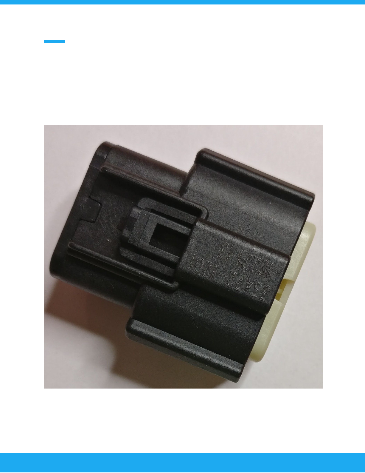
Inserting the crimped pin into the connector body
Step1:
Make sure that the “white” plastic part from inside the connector is pulled out. This can be
verified by making sure that the plastic piece is protruding from the connector. If the plastic is not
showing, you can use a small screwdriver to pry it out from the connector.
7
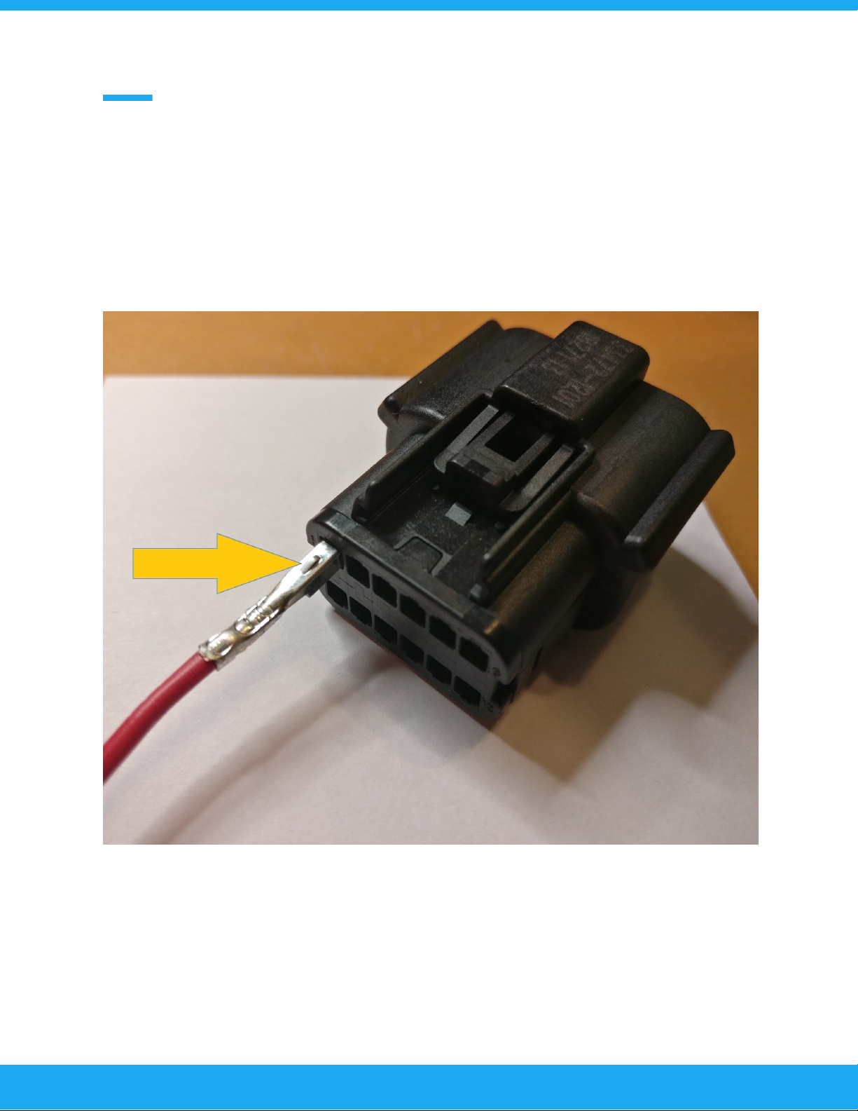
Step 2:
Insert the crimped pin from behind the connector body. There is a small dimple on the pin that
marks the correct orientation of the pin. Top row has the dimple on top and bottom row at
bottom. You can hear an audible click as the connector is seated. Tug on the wire to confirm
proper pin seating.
After all pins have been inserted push the “white” plastic piece in to the connector to lock all the
pins in place. Now the wiring of the connector is complete.
8

Wiring diagrams
Power and CAN-bus wiring
Use a 10A fuse. The controller will use the fuse as part of the polarity protection.
GND connections should be connected to the battery negative terminal without interrupts. This
results in the best operation.
From electronics revision C onvard controller has a user programmable CAN-bus termination
resistor that can be enabled from the tuning software. Also an open collector output has been
added. This is a grounding type output. This is intended to be used as a “main power” for the
engine to provide an additional layer of safety. Installer can configure this output to be normally
open / normally closed or PWM.
9
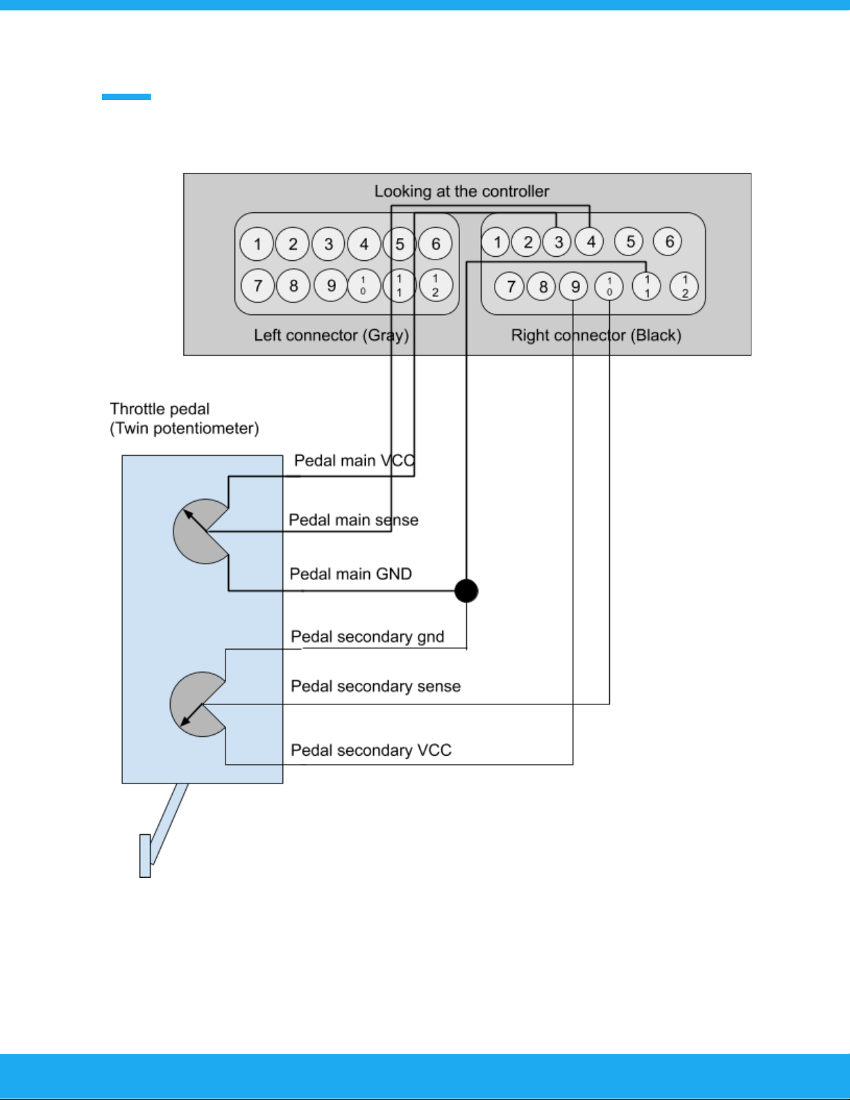
Wiring the accelerator pedal
10
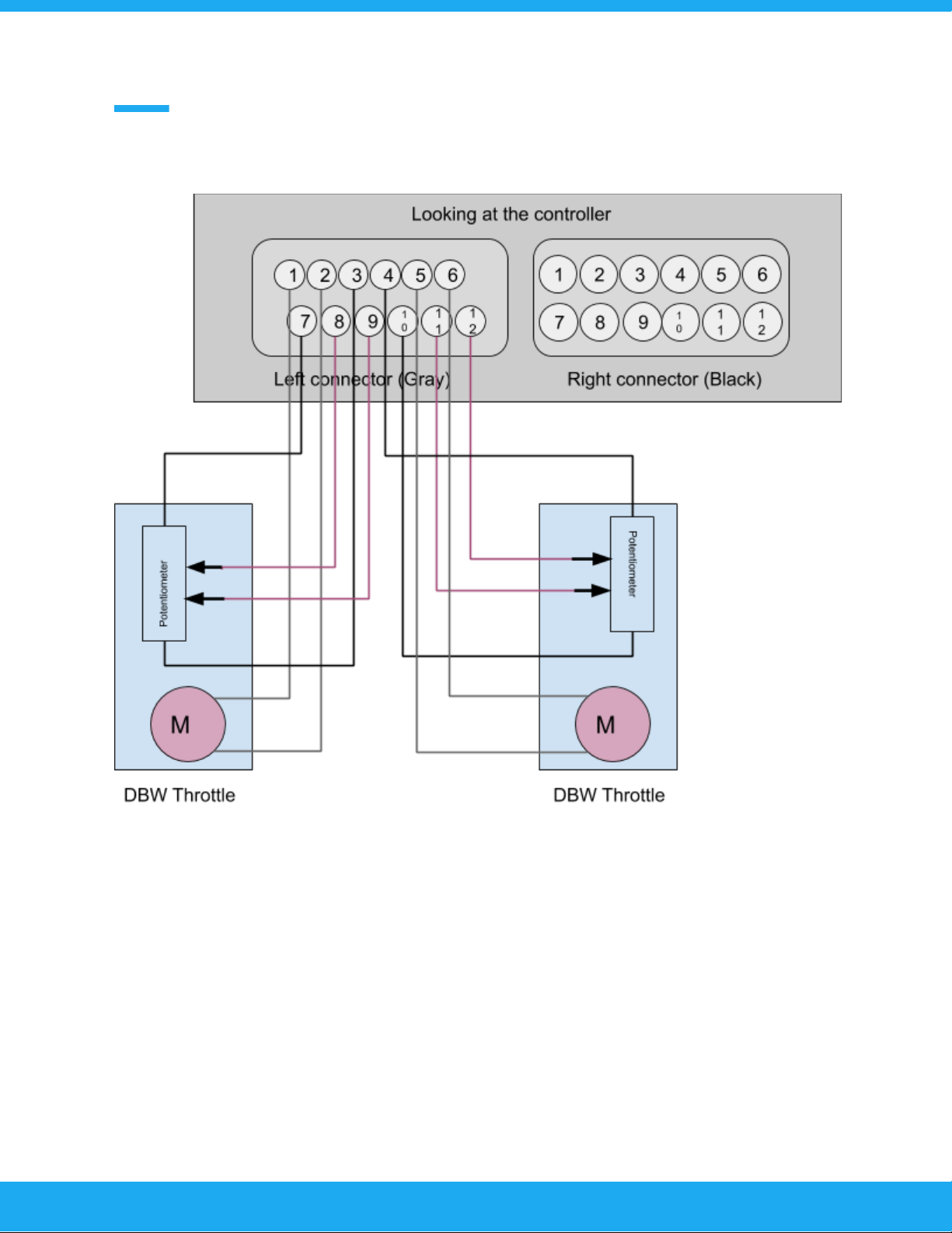
DBW connections
11
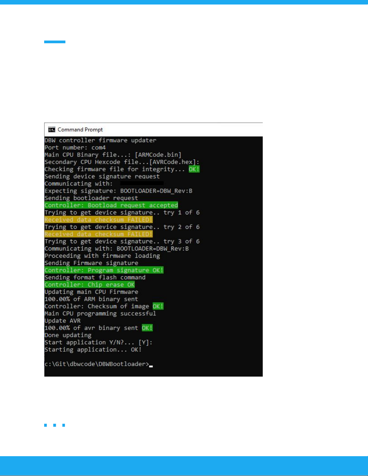
Updating the controller
To update the controller it must be powered from a 12V source. Shut down Tunerstudio if its
running. After unzipping the firmware update you should see firmwareupdater.exe (or similar
name). Double click on it to start the update.
You can press [ENTER] for every question so that defaults will be selected. Successful update can
be verified by connecting to the controller with Tunerstudio.
12
Understanding fault codes
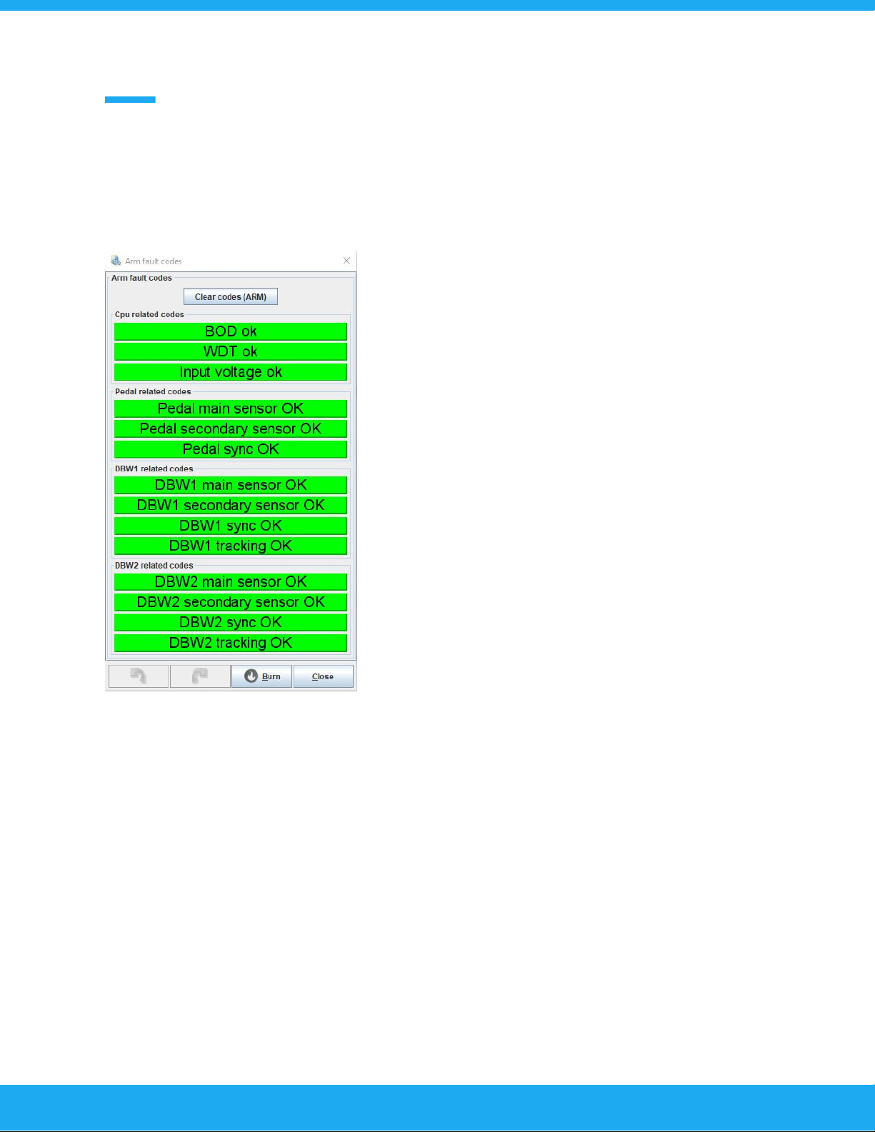
ARM Fault codes
Fault code system was added to aid in fault finding. It is
important to understand what causes a particular error
condition in the controller.
BOD error: This is a CPU error that is caused by a low
voltage condition to reset the cpu. Causes include
external error on 5V reference voltage output and internal
power supply failure.
WDT error: This is a CPU error. The CPU has taken too
long to do a task and that has triggered the internal
watchdog timer. The firmwares are tested and it is not
normal to see this error.
Input voltage error: This warning is tripped if the input
voltage goes momentarily below 11 volts. This is an aid to
the installer to check the wiring to the controller if this
warning is shown.
Pedal main and secondary sensor error: This error is
triggered if the input voltage from the accelerator pedal sensor is out of calibrated specification.
Pedal sync error: This error is triggered if the calculated percentage values from main and
secondary sensors differ by a user set amount. This is only done in “linear” throttle calibration
mode. If the “table” calibration is done this error is set if the secondary sensor voltage differs
from the value read from the table.
DBW sensor errors are exactly same as pedal errors.
DBW tracking error: If the DBW actual position does differ too much from the target position this
error is set.
13
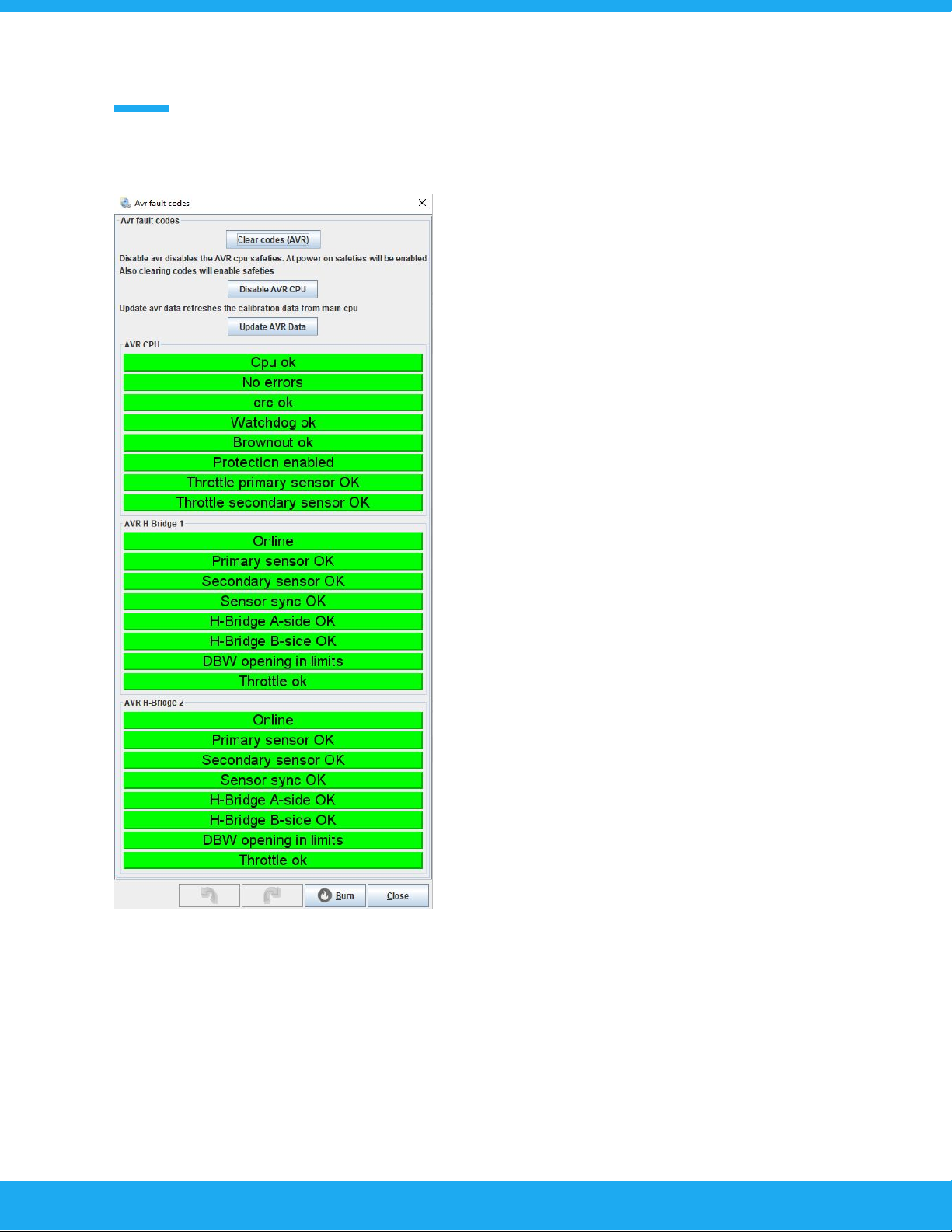
AVR Fault codes
The AVR cpu has the same fault diagnosis as the
main ARM cpu. The reason behind the addon of a
secondary CPU is redundancy. If the main cpu failed
such that it would command the throttle(s) open, the
secondary cpu will still be able to save the situation
by disabling the DBW(s) completely.
Clear codes button: Self explanatory.
Disable AVR CPU button: This disables the fault
checking of the secondary CPU. This is mandatory
for calibration purposes. The disabled status is
shown by the “protection enabled / disabled”
indicator.
Update AVR data button: This button makes the
main CPU to resend the calibration data to the AVR
CPU. If a fault condition is not cleared by clear
button, try to update the avr data to see if the fault
condition was caused by calibration data mismatch.
The sensor fault codes are the same as in the ARM
fault code menus.
Compared to the ARM codes there are a few extras.
The AVR CPU monitors the H-bridge statuses and
these can be seen from this menu. If a H-Bridge
error status is flagged and nothing else it means that
the H-Bridge output has a short or the bridge driver
has overheated. This error may also be displayed
when the h-bridge is disabled from other error
sources.
DBW opening in limits: If the DBW is opened more that what has been defined in the “DBW
Maximum opening” tables triggers this error.
14
PID Settings
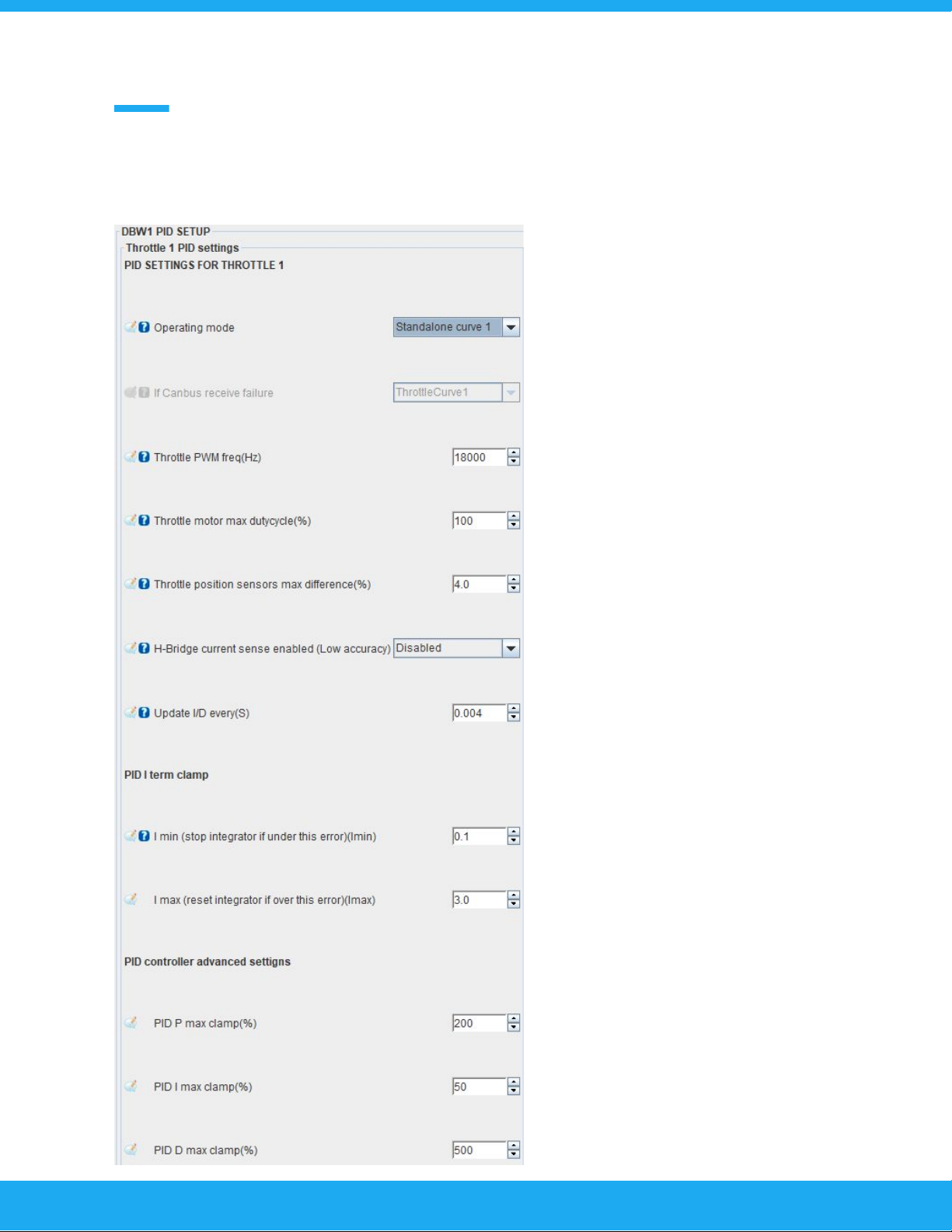
Operating modes:
-Off : Channel is offline
-Standalone curve 1 & 2: Controller is in
standalone mode and will use throttle
curve 1 or 2 to map the opening of the
DBW throttlebody to the accelerator
pedal position.
-MS Can: Controller will receive the
DBW throttlebody opening request from
CAN-bus. The next setting below is
what will the controller do if the
CAN-bus message is not received for
any reason. Selectable options are “off”
or one of the throttle curves.
Throttlebody specific
settings:
-Throttle PWM Frequency: This setting
selects the operating frequnecy. Range
is from 750Hz to 20000Hz. The
H-Bridge works at better efficiency if a
lower frequency is selected, but there
will be an audible noise from the DBW
throttlebody.
Throttle motor max dytycycle: This
setting can be used to limit the
maximum current that the DBW motor
can take. Usually left at 100%
Throttle sensor max difference: This
setting tells the controller at what
15

sensor difference will a fault be triggered. Default value is 4%
H-Bridge current sense enable: This setting enables the current sense circuitry in the H-Bride.
This circuitry is around 15% accuracy from full scale (30A). This means that it cannot be used for
precision measurement, but it can measure relative changes in current. Enabling this will enable
logging of the current and the current gauge. If this setting is disabled the current gauge will
display 0A.
Update I/D: This is the PID controller update frequency.
PID I MIN: Often referred as “deadband”. The PID integrator is paused when the position error is
smaller than what is set.
I MAX: To prevent PID controller integrator windup this setting can be used to reset the integrator
to 0 when position error is larger that set value. To disable this put in 100%.
PID clamp settings:
This setting can limit the maximum PID calculation outputs. The PID controllers internal register
are logged, and can be viewed from the logs. These values will clamp the calculated values to
the set values.
BIAS
The DBW controller also has a table that is called either “bias” or “feed forward” table. This is
basically an open loop of the control strategy. We have found that a well tuned PID control may
not need this table at all, but it is provided. The “bias” value is a duty cycle value that is given to
the DBW throttlebody for a given “target” opening. The dytycyle can be from -100 to +100.
Negative values driving the butterfly closed and vice versa.
Throttle body sensor calibration
The position sensors of the DBW throttlebody are calibrated automatically by the controller. User
needs to disable AVR protection from the AVR fault code menu. Then press “Calibrate” button
and the controller will drive the butterfly first fully open and the fully closed and records the
sensor readings. This works only for regular DBW throttlebodys that have linear sensors.
16
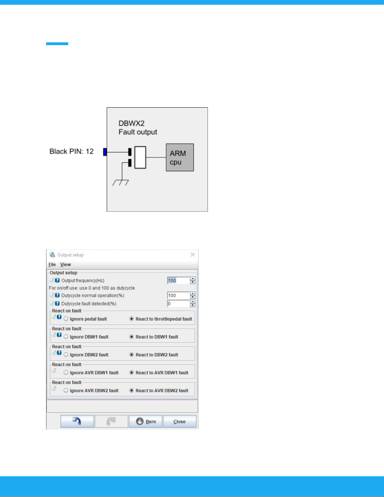
Configuring fault output
Circuit:
Fault output is an open collector low side output. Current is limited to 10A but it is not
recommended to load the output beyond 5Amps because of thermal concerns.
User can configure the outputs PWM
frequency and dutycycle in normal and fault
operation.
Also the configuration makes possible to
ignore faults in channels that are used as
auxiliary channels that does not require the
fault output to be tripped.
Default state of the channel is high
impedance (0% duty). It is recommended to
make the connected external circuit operate
so that fault state is 0% duty.
17

Step by step initial configuration guide
At this point the controller should be wired correctly.
Now open TunerStudio and start a new project. After you have successfully connected to the
DBWX2 controller the first thing to do is calibrate the DBW throttlebody.
1. Open the “DBW1” or “DBW2” menu and click on the “DBW auto min/max”
When you open this setting you will find that it says ready to
calibrate and AVR protection enabled. This means that the
throttlebody cannot yet be calibrated as the AVR co-cpu will
interfere with the calibration. We will now disable the AVR
co-cpu, so that we can proceed with the DBW throttlebody
calibration.
This is done from “Fault Codes” -> AVR Fault codes. You will
find a button that is labeled “Disable AVR CPU”. Click on it and
you will see the text in the throttlebody calibration menu
change to “AVR Protection disabled” and change color to blue
from yellow. Also you will get a faultcode in the AVR indicating
that the protection features is disabled.
Now you can press on the “Calibrate DBW” button and the
controller will automatically drive the DBW throttlebody to the
maximum and minimum positions and save the calibrated sensor settings.
Do this for both DBW throttlebodies if you have more than one connected.
NOTE: When calibrating the DBW Throttle butterly should first go in to the fully open position and
after that it should fully close. If you have the motor positive and negative wires crossed it will
calibrate the throttlebody so that 0% is fully open and vice versa. It is the responsibility of the
installer to check that the operation is correct.
Next step is to calibrate the accelerator pedal.
18
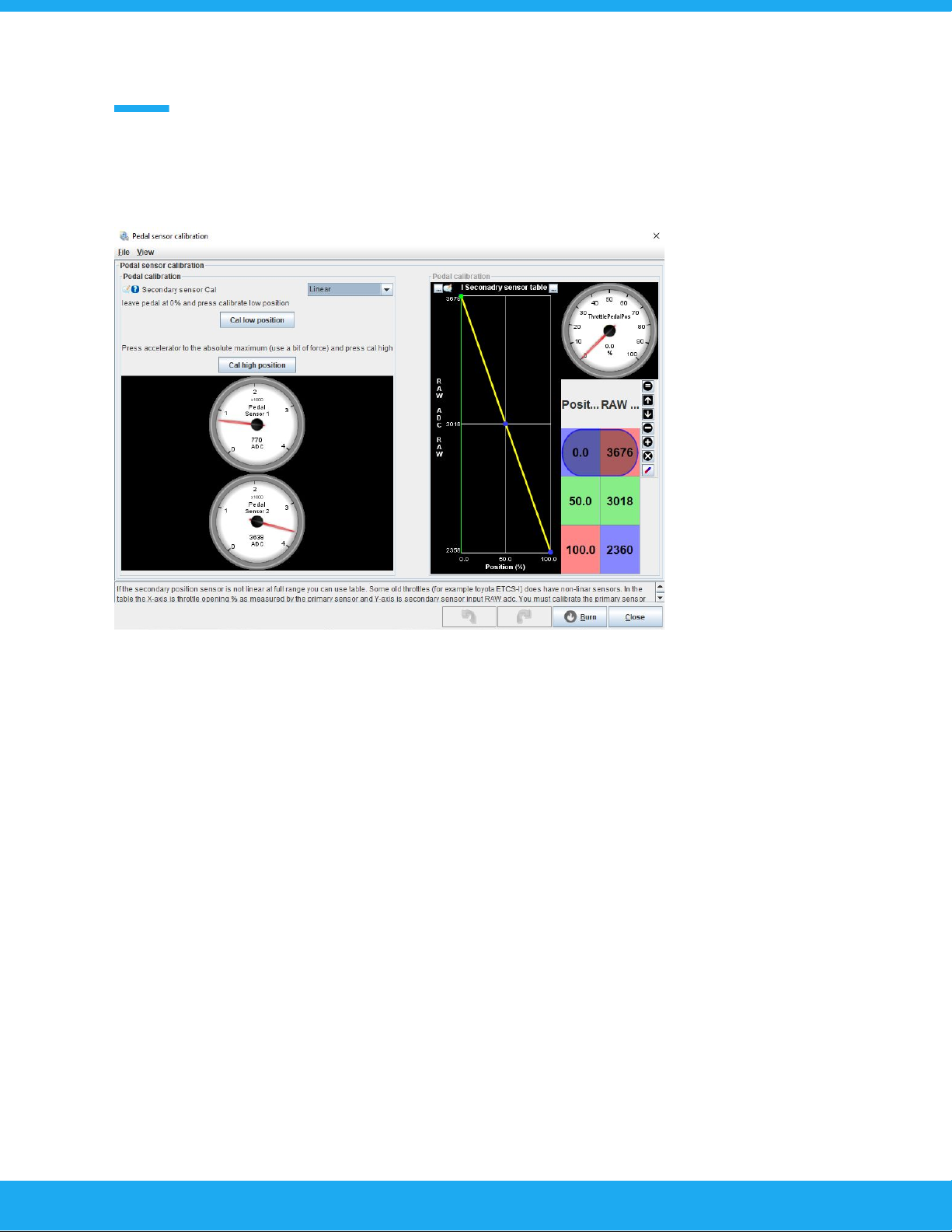
2. Calibrate the accelerator pedal
Open the “Setup” menu and click on the “Pedal calibration”
Now leave the throttle untouched and click on the “Cal low position”.
Now the 0% position has been calibrated. Fully depress the accelerator pedal with some force.
Press “Cal high position”. This is so that when driving the car in anger the driver can stomp on the
accelerator and it will read past 100%. This will cause an error code and will result in the
controller entering limp mode.
Make sure that the secondary sensor cal is “Linear”. The “table” is only used with uncommon
sensors from the early 2000 era.
Now we have calibrated all of the sensors. You will probably have fault codes registered in the
controller. Go in to the “Fault Codes” menu and clear all coder from the ARM and AVR cpu’s.
Next step is PID setup for the throttlebody.
19
Table of contents


