manuals.online logo
Brands
  1. Home
  2. •
  3. Brands
  4. •
  5. SMC Networks
  6. •
  7. Controllers
  8. •
  9. SMC Networks C96 Series User manual

SMC Networks C96 Series User manual

Other manuals for C96 Series

1

Other SMC Networks Controllers manuals
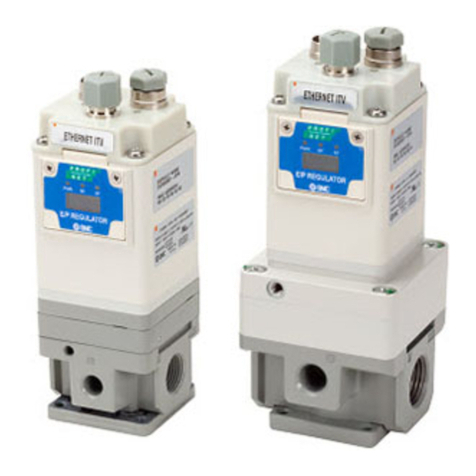
SMC Networks AWM20-01 Series User manual

SMC Networks

SMC Networks AWM20-01 Series User manual

SMC Networks PFCA7 Series User manual

SMC Networks

SMC Networks PFCA7 Series User manual

SMC Networks FC3W5 Series User manual

SMC Networks

SMC Networks FC3W5 Series User manual

SMC Networks 10-AW Series User manual

SMC Networks

SMC Networks 10-AW Series User manual

SMC Networks MQ Series User manual

SMC Networks

SMC Networks MQ Series User manual

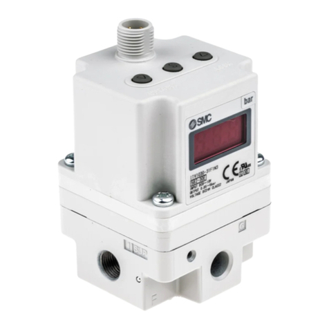
SMC Networks ITV 1 Series User manual

SMC Networks

SMC Networks ITV 1 Series User manual

SMC Networks CRQ2X User manual

SMC Networks

SMC Networks CRQ2X User manual

SMC Networks LC8-B*H*-M*-Q Series Manual

SMC Networks

SMC Networks LC8-B*H*-M*-Q Series Manual

SMC Networks LEY series User manual

SMC Networks

SMC Networks LEY series User manual

SMC Networks LECP1 Series User manual

SMC Networks

SMC Networks LECP1 Series User manual

SMC Networks ITV10*0-X305 Manual

SMC Networks

SMC Networks ITV10*0-X305 Manual

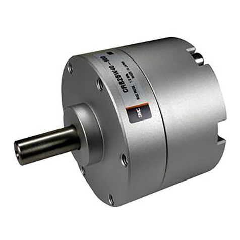
SMC Networks ITV SEN DUX02357 Series User manual
SMC Networks

SMC Networks ITV SEN DUX02357 Series User manual

SMC Networks ITV1000-IO Series User manual

SMC Networks

SMC Networks ITV1000-IO Series User manual

SMC Networks VCHR40 Series Manual

SMC Networks

SMC Networks VCHR40 Series Manual

SMC Networks RS2H Series User manual

SMC Networks

SMC Networks RS2H Series User manual

SMC Networks MXQ6 Series User manual

SMC Networks

SMC Networks MXQ6 Series User manual

SMC Networks ITV2010-X155 Manual

SMC Networks

SMC Networks ITV2010-X155 Manual

SMC Networks JXC51 User manual

SMC Networks

SMC Networks JXC51 User manual

SMC Networks ZL3 Series User manual

SMC Networks

SMC Networks ZL3 Series User manual

SMC Networks CRB2BW40 Series User manual
SMC Networks

SMC Networks CRB2BW40 Series User manual

SMC Networks CRA1 Series User manual

SMC Networks

SMC Networks CRA1 Series User manual

SMC Networks JXCEH User manual

SMC Networks

SMC Networks JXCEH User manual

SMC Networks LEYG25M Manual

SMC Networks

SMC Networks LEYG25M Manual

SMC Networks EQY Series User manual

SMC Networks

SMC Networks EQY Series User manual

Popular Controllers manuals by other brands

Sunricher SR-ZV9003T3-RGBW-US Installation

Sunricher

Sunricher SR-ZV9003T3-RGBW-US Installation

Ksenia intro Installation and configuration manual

Ksenia

Ksenia intro Installation and configuration manual

Inovance CAN200 Series manual

Inovance

Inovance CAN200 Series manual

Gauzy LC6 FLEX Controller Installation and operation guide

Gauzy

Gauzy LC6 FLEX Controller Installation and operation guide

Viking SLP-1 Technical practice

Viking

Viking SLP-1 Technical practice

CKD KBX-30E-U Series instruction manual

CKD

CKD KBX-30E-U Series instruction manual

Sharp Energy Sun Flux User manual & installation guide

Sharp Energy

Sharp Energy Sun Flux User manual & installation guide

Yamaha RCX40 user manual

Yamaha

Yamaha RCX40 user manual

AB Quality PowerFlex 400 Frames D-H Service bulletin

AB Quality

AB Quality PowerFlex 400 Frames D-H Service bulletin

Yamaha MJC8 owner's manual

Yamaha

Yamaha MJC8 owner's manual

AL-KO ATC operating instructions

AL-KO

AL-KO ATC operating instructions

Savant SmartControl 2 Deployment guide

Savant

Savant SmartControl 2 Deployment guide

GameSir T3S user manual

GameSir

GameSir T3S user manual

Kostal inveor operating manual

Kostal

Kostal inveor operating manual

Emerson Yarway 20-55 Operating and safety instructions

Emerson

Emerson Yarway 20-55 Operating and safety instructions

CoCo ACM-LV24 Quick installation guide

CoCo

CoCo ACM-LV24 Quick installation guide

Brooks SLA5810/20 Installation and operation manual

Brooks

Brooks SLA5810/20 Installation and operation manual

SIGMA TEK SR 011 Technical manual

SIGMA TEK

SIGMA TEK SR 011 Technical manual

manuals.online logo
manuals.online logoBrands
  • About & Mission
  • Contact us
  • Privacy Policy
  • Terms and Conditions

Copyright 2025 Manuals.Online. All Rights Reserved.

By adopting a new cushion method (Air cushion + Bumper cushion),
Cycle time shortened
Bumper cushion reduces the metal noise that occurs when piston stops
Existing
Air cushion
Air cushion
Air cushion
Bumper cushion
Air cushion
Bumper cushion
NewNew +
Cushion stroke time
Shortened
*Compared with the existing C96 series (ø40, 100 stroke)
Lightweight
17
% Weight reduced
Up
to
Series C96
ISO Cylinder
ø32, ø40, ø50, ø63, ø80, ø100
ISO Standard (15552)
CAT.ES20-242A
New Series C96
Combined
structure
Bumper cushion
Auto switch mounting bracket
Auto switch mounting screw
Phillips screwdriver Watchmaker’s
screwdriver
Hexagon wrench
(Width across flats
2.5 mm)
Hexagon wrench
(Width across flats
2.5 mm)
*Compared with the existing C96 series (ø40, 100 stroke)
Air cushion
OThe cushion stroke time can now be reduced with the double
cushioning, which improves the cycle time.
OThe bumper cushion reduces the metal noise that occurs when
the piston stops at the end of the stroke.
Improved handling performance
Small sized auto switch can be attached.
Tie-rod mounting
auto switch
Direct mounting
auto switch
Direct mounting auto
switch can be fixed to the
tie-rod with a dedicated
switch mounting bracket.
Auto switch mounting and mounting position adjustment can be made in a one way direction.
Solid state: D-M9lReed: D-A9l
D-M9lW
2-way
Existing New method
1-way
Bore size
(mm) NewNew C96 Reduction rate
32 0.65 13%
40 0.96 17%
50 1.57 13%
63 1.94 14%
80 3.12 13%
100 4.03 12%
(kg)
Weight reduced
Achieved weight reduction by changing rod cover shape
and piston structure
Air cushion
Bumper cushion
+
Rod end nut
can be screwed
up to TRP.
TRP
1
Various mounting bracket options
Mounting brackets can be combined according to the operating conditions.
ISO Cylinder
Piston rod
ball joint (KJ)
Rod clevis (GKM)
Floating
joint (JA)
Rod flange (F)
Axial foot (L)
Double clevis (D)
Clevis pivot
bracket (E)
Single clevis (C)
Double clevis
pivot bracket (DS)
Clevis pivot bracket
with ball joint (ES)
Single clevis
with ball joint (CS)
Single clevis
with ball joint (CS)
Head flange (G)
Axial foot (L)
Single clevis (C)
Series C96
2
3
Nil 2 pcs.
S1 pc.
33 pcs.
n“n” pcs.
Nil Without auto switch
C96S B 32 100
C96SD B S
32 100 M9BW
Auto switch
Number of auto switches
∗For applicable auto switches,
refer to the table below.
How to Order
C
C
Air cushion on both ends + Bumper cushion
Applicable Auto Switches/Refer to the WEB catalog or the Best Pneumatics No. 2 for further information on auto switches.
ø32, ø40, ø50, ø63, ø80, ø100
Air Cylinder: Standard Type
Double Acting, Single Rod
Series C96
∗1 Water resistant type auto switches can be mounted on the above models, but in such case SMC cannot guarantee water resistance.
∗Lead wire length symbols: 0.5 m ········· Nil (Example) M9NW
1 m ········· M (Example) M9NWM
3 m ········· L (Example) M9NWL
5 m ········· Z (Example) M9NWZ
∗Since there are other applicable auto switches than listed above, refer to the WEB catalog or the Best Pneumatics No. 2 for details.
∗For details about auto switches with pre-wired connector, refer to the WEB catalog or the Best Pneumatics No. 2.
∗The D-A9l/M9l/M9lW/M9lA auto switches are shipped together, (but not assembled).
(However, only the auto switch mounting brackets are assembled before shipment.)
With auto switch
With auto switch
(Built-in magnet)
Bore size
Mounting
∗
Mounting brackets are shipped
together, (but not assembled).
(except center trunnion type)
Cylinder stroke
(mm)
Refer to “Standard
Strokes” on page 4.
BBasic
LAxial foot
FRod flange
GHead flange
CSingle clevis
DDouble clevis
TCenter trunnion
32 32 mm
40 40 mm
50 50 mm
63 63 mm
80 80 mm
100 100 mm
Type Special function Electrical
entry
Indicator
light
Wiring
(Output)
Load voltage Auto switch model Lead wire length (m) Pre-wired
connector
Applicable
load
DC AC Tie-rod
mounting
Band
mounting
0.5
(Nil)
1
(M)
3
(L)
5
(Z)
Solid state auto switch
—
Grommet
Yes
3-wire (NPN)
24 V 5 V, 12 V —
M9N —VVVv v IC
circuit
Relay,
PLC
3-wire (PNP) M9P —VVVv v
2-wire 12 V M9B —VVVv v —
— — 100 V, 200 V J51 —V—V v —
Terminal
conduit
3-wire (NPN)
24 V
5 V, 12 V
—
—G39 ———— —
IC circuit
2-wire 12 V — K39 — — — — — —
Diagnostic indication
(2-color indication)
Grommet
3-wire (NPN) 5 V, 12 V M9NW —VVVv v IC
circuit
3-wire (PNP) M9PW —VVVv v
2-wire 12 V M9BW —VVVv v —
Water resistant
(2-color indication)
3-wire (NPN) 5 V, 12 V M9NA∗1—vvVv v IC
circuit
3-wire (PNP) M9PA∗1—vvVv v
2-wire 12 V M9BA∗1—vvVv v —
With diagnostic output
(2-color indication) 4-wire (NPN) 5 V, 12 V F59F —V—V v v IC
circuit
Magnetic field resistant
(2-color indication)
2-wire
(Non-polar) —P4DW — — — V V v —
Reed auto switch
—
Grommet
Yes
3-wire
(NPN Equivalent)
— 5 V — A96 —V—V— — IC
circuit —
2-wire 24 V
12 V
100 V A93 —VVVV — —
Relay,
PLC
No 100 V or less A90 —V—V— —
IC circuit
Yes 100 V, 200 V A54 —V—V V —
—
No 200 V or less A64 —V—V— —
Terminal
conduit
Yes
— — A33 — — — — — PLC
100 V, 200 V —A34 ———— —
Relay,
PLC
DIN terminal
—A44 ———— —
Diagnostic indication
(2-color indication) Grommet — — A59W —V—V— —
ISO Standard (15552)
∗Solid state auto switches marked with “v” are produced upon receipt of order.
A
4
ISO Standard (15552) Air Cylinder: Standard Type
Double Acting, Single Rod Series C96
Bore size (mm) 32 40 50 63 80 100
Action Double acting
Fluid Air
Proof pressure 1.5 MPa
Max. operating pressure
1.0 MPa
Min. operating pressure
0.05 MPa
Ambient and fluid
temperature
Without auto switch: –20 to 70°C (No freezing)
With auto switch : –10 to 60°C (No freezing)
Lubrication Not required (Non-lube)
Operating piston speed
50 to 1000 mm/s
Allowable stroke
tolerance
Up to 500 stroke: +2
0, 501 to 1000 stroke: +2.4
0 ,
1001 to 1500 stroke: +2.8
0 , 1501 to 2000 stroke: +3.2
0
Cushion Air cushion on both ends + Bumper cushion
Port size G1/8 G1/4 G1/4 G3/8 G3/8 G1/2
Mounting
Basic, Axial foot, Rod flange,
Head flange, Single clevis, Double clevis,
Center trunnion
Specifications
Minimum Stroke
for Auto Switch Mounting
Refer to “Minimum Stroke for Auto Switch
Mounting” on page 13.
Standard Strokes
Intermediate strokes are available.
Note) Please consult with SMC for longer strokes.
Accessories
*Do not use a piston rod ball joint (or floating joint) together with a single clevis with a ball joint
(or clevis pivot bracket with a ball joint).
Mounting Basic Foot Rod
flange
Head
flange
Single
clevis
Double
clevis
Center
trunnion
Standard Rod end nut V V V V V V V
Clevis pin — — — — — V—
Option
Piston rod ball joint
V V V V V V V
Rod clevis V V V V V V V
Rod boot V V V V V V V
Bore size
(mm)
Standard stroke
(mm)
Max.
stroke Note)
32 25, 50, 80, 100, 125, 160, 200, 250, 320, 400, 500 1000
40 25, 50, 80, 100, 125, 160, 200, 250, 320, 400, 500 1900
50 25, 50, 80, 100, 125, 160, 200, 250, 320, 400, 500, 600 1900
63 25, 50, 80, 100, 125, 160, 200, 250, 320, 400, 500, 600 1900
80 25, 50, 80, 100, 125, 160, 200, 250, 320, 400, 500, 600, 700, 800 1900
100 25, 50, 80, 100, 125, 160, 200, 250, 320, 400, 500, 600, 700, 800 1900
OUT IN
1 10 100 1000
100
1000
1
Maximum speed (mm/s)
Load mass (kg)
ø100
ø80
ø63
ø50
ø40
ø32
Bore
size
(mm)
Rod size
(mm)
Operating
direction
Piston
area
(mm2)
Operating pressure (MPa)
0.2 0.3 0.4 0.5 0.6 0.7 0.8 0.9 1.0
32 12 OUT 804 161 241 322 402 482 563 643 724 804
IN 691 138 207 276 346 415 484 553 622 691
40 16 OUT 1257 251 377 503 629 754 880 1006 1131 1257
IN 1056 211 317 422 528 634 739 845 950 1056
50 20 OUT 1963 393 589 785 982 1178 1374 1570 1767 1963
IN 1649 330 495 660 825 989 1154 1319 1484 1649
63 20 OUT 3117 623 935 1247 1559 1870 2182 2494 2805 3117
IN 2803 561 841 1121 1402 1682 1962 2242 2523 2803
80 25 OUT 5027 1005 1508 2011 2514 3016 3519 4022 4524 5027
IN 4536 907 1361 1814 2268 2722 3175 3629 4082 4536
100 25 OUT 7854 1571 2356 3142 3927 4712 5498 6283 7068 7854
IN 7363 1473 2209 2945 3682 4418 5154 5890 6627 7363
Bore size (mm) 32 40 50 63 80 100
Basic weight
Basic 0.43 0.64 1.09 1.42 2.32 3.15
Foot 0.16 0.20 0.38 0.46 0.89 1.09
Flange 0.20 0.23 0.47 0.58 1.30 1.81
Single clevis 0.16 0.23 0.37 0.60 1.07 1.73
Double clevis 0.20 0.32 0.45 0.71 1.28 2.11
Trunnion 0.71 1.10 1.73 2.48 4.25 5.95
Additional weight
per 50 mm of stroke
All mounting
brackets 0.11 0.16 0.24 0.26 0.40 0.44
Accessories Piston rod ball joint 0.07 0.11 0.22 0.40
Rod clevis 0.09 0.15 0.34 0.69
(N)
Note) Theoretical output (N) = Pressure (MPa) x Piston area (mm2)
(kg)
Theoretical Output
Weights
Allowable Kinetic Energy
(Example) Find the upper limit of rod end load
when an air cylinder of ø63 is operated
at 500 mm/s. From a point indicating
500 mm/s on the axis of abscissas, ex-
tend a line upward and find a point
where it intersects with a line for the 63
mm bore size. Extend a line from the
intersection to the left and find a load
mass 80 kg.
Calculation: Example) C96SD40-100C
OBasic weight ····························· 0.64 (kg) (Basic, ø40)
OAdditional weight ······················ 0.16 (kg/50 st)
OCylinder stroke ························· 100 (st)
OMounting bracket weight ·········· 0.32 (kg) (Double clevis)
0.64 + 0.16 x 100 ÷ 50 + 0.32 = 1.28 kg
5
Series C96
ø80, ø100
ø80, ø100
q e r y
u
t i w!2 !9 !4 !5 !6 !8 @2 !7 @0!3 @1
o !0
!1 !0
Bore size (mm) Kit no. Contents
32 CS95-32
Kits include items
!5, !7, !8, !9, @0.
40 CS95-40
50 CS95-50
63 CS95-63
80 CS95-80
100 CS96-100
No. Description Material Note
1 Rod cover Aluminum die-cast
2 Head cover Aluminum die-cast
3 Cylinder tube Aluminum alloy
4 Piston rod Carbon steel
5 Piston Aluminum alloy ø32 to ø63
Aluminum die-cast ø80, ø100
6 Cushion ring A Aluminum alloy
7 Cushion ring B Aluminum alloy
8 Cushion seal holder Aluminum alloy
9 Tie-rod Carbon steel
10 Tie-rod nut Steel
11 Flat washer Steel ø80, ø100
12 Rod end nut Steel
13 Cushion valve Resin
14 Bushing Bearing alloy
15 Cushion seal Urethane
16 Bumper Urethane
17 Wear ring Resin
18 Piston seal NBR
19 Rod seal NBR
20 Cylinder tube gasket NBR
21 Cushion valve seal NBR
22 Magnet
Replacement Parts/Seal Kit (Single rod)
*Seal kits consist of items !5, !7, !8, !9, @0 and can be ordered by
using the seal kit number corresponding to each bore size.
*The seal kit includes a grease pack (10 g for ø32 to ø50, 20 g for
ø63 and ø80, 30 g for ø100).
Order with the following part number when only the grease pack
is needed.
Grease pack part number: GR-S-010 (10 g), GR-S-020 (20 g)
Component Parts
Construction [First angle projection]
6
ISO Standard (15552) Air Cylinder: Standard Type
Double Acting, Single Rod Series C96
7
Series C96
ø80, ø100
ø80, ø100
ø32, ø40
E
R
E
R
øD
øB
ZZ + Stroke
L8+ Stroke
G
VA
BG
L9
G
H
WHA
BGL2
VD
L12
2x 4x RT
PL
WB
WA
WA
WB
KK
SL
PL
øB
BG
2x 4x RT
Width across flats SW PL
Cushion valve
2x EE
2x EE
port
Bore
size
(mm)
Stroke
range
(mm)
A
øB
d11
BG
øD E EE G H KK L2L8L9L12 PL R RT
SL
SW
VA VD
WA WB
WH
ZZ
32
Up to 1000
22 30 16 12 47 G 1/8 28.9 48
M10 x 1.25
15 94 4 6 13 32.5
M6 x 1
8 10 4 4 4 7 26 146
40
Up to 1900
24 35 16 16 54 G 1/4 32.6 54
M12 x 1.25
17 105 4 6.5 14 38
M6 x 1
8 13 4 4 5 8.9 30 163
50
Up to 1900
32 40 16 20 66 G 1/4 32 69
M16 x 1.5
24 106 5 8 14 46.5
M8 x 1.25
— 17 4 4 6 5.1 37 179
63
Up to 1900
32 45 16 20 77 G 3/8 38.6 69
M16 x 1.5
24 121 5 8 16 56.5
M8 x 1.25
— 17 4 4 9 6.3 37 194
80
Up to 1900
40 45 17 25 99 G 3/8 38.4 86
M20 x 1.5
30 128 — 10 16 72
M10 x 1.5
— 22 4 4 11.5 6 46 218
100
Up to 1900
40 55 17 25 118 G 1/2 42.9 91
M20 x 1.5
32 138 — 10 18 89
M10 x 1.5
— 22 4 4 17 10 51 233
Dimensions
Basic: C96S (D) B C
Bore size Stroke
(mm)
[First angle projection]
8
ISO Standard (15552) Air Cylinder: Standard Type
Double Acting, Single Rod Series C96
E1
TR
AH
XA + Stroke
4 x øAB
AT
AO AO
SA + Stroke
Z+ 1/2 stroke
XV + 1/2 stroke
L1
UW
øTD
TL TM TL
R
E2
4 x FB
TF
UF
WMF
EW
CB
UB
EB
ZF + Stroke MF
CD
XD + Stroke LMR
Dimensions
Axial foot (L)
Center trunnion (T)
Head flange (G)
Rod flange (F)
Single clevis (C)
Double clevis (D)
Single clevis (C)
Double clevis (D)
Bore
size
(mm)
E1
TR
AH AO
AT AB SA XA
32 48 32 32 10 4.5
7
142 144
40 55 36 36 11 4.5
10
161 163
50 68 45 45 12 5.5
10
170 175
63 80 50 50 12 5.5
10
185 190
80 100 63 63 14 6.5
12
210 215
100 120 75 71 16 6.5
14.5
220 230
(mm)
Bore
size
(mm)
TM TL
TD
e8 UW
L1XV Z
32 50 12 12 49 17
73 95
40 63 16 16 58 22
82.5 106.5
50 75 16 16 71 22
90 122
63 90 20 20 87 28
97.5 129.5
80 110 20 20 110 34
110 150
100 132 25 25 136 40
120 160
(mm)
Bore
size
(mm)
R TF FB E2UF W MF
32 32 64 7 50 79 16 10
40 36 72 9 55 90 20 10
50 45 90 9 70 110 25 12
63 50 100 9 80 120 25 12
80 63 126 12 100 153 30 16
100 75 150 14 120 178 35 16
(mm)
Bore
size
(mm)
MF ZF
32 10 130
40 10 145
50 12 155
63 12 170
80 16 190
100 16 205
(mm)
Bore
size
(mm)
EW
CD
H9
L MR XD
UB
h14
CB
H14
EB
32 26–0.2
–0.6 10 12
9.5
142 45 26 65
40 28–0.2
–0.6 12 15
12
160 52 28 75
50 32–0.2
–0.6 12 15
12
170 60 32 80
63 40–0.2
–0.6 16 20
16
190 70 40 90
80 50–0.2
–0.6 16 20
16
210 90 50 110
100 60–0.2
–0.6 20 25
20
230 110 60 140
(mm)
[First angle projection]
9
R
2
TG
TG/2
E
TR
AH
AT
AU
AO
øAB
FB
ø
D
R
E
UF
TF
TG
TG
MF
L4
øCDH9
l
2
l
1
Bore
size
(mm)
Part no. AB TG
±0.2 E TR AO AU AH AT R2Screw size
32
L5032
7 32.5 48 32 10 24 32 4.5 15 M6 x 16L
40
L5040
10 38 55 36 11 28 36 4.5 17.5 M6 x 16L
50
L5050
10 46.5 68 45 12 32 45 5.5 20 M8 x 20L
63
L5063
10 56.5 80 50 12 32 50 5.5 22.5 M8 x 20L
80
L5080
12 72 100 63 14 41 63 6.5 22.5 M10 x 20L
100
L5100
14.5 89 120 75 16 41 71 6.5 27.5 M10 x 20L
Bore
size
(mm)
Part no. D
H11
øFB TG
±0.2 E R MF TF UF L4Screw size
32
F5032
30 7 32.5 50 32 10 64 79 5 M6 x 20L
40
F5040
35 9 38 55 36 10 72 90 5 M6 x 20L
50
F5050
40 9 46.5 70 45 12 90 110 6.5 M8 x 20L
63
F5063
45 9 56.5 80 50 12 100 120 6.5 M8 x 20L
80
F5080
45 12 72 100 63 16 126 153 9 M10 x 25L
100
F5100
55 14 89 120 75 16 150 178 9 M10 x 25L
Bore
size
(mm)
Part no. E1EW TG1FL l1Ll2ød1øCD MR ød2R1
32
C5032
45 26
–0.2
–0.6
32.5 22 5 12 5.5 30 10 9.5 6.6 6.5
40
C5040
51 28
–0.2
–0.6
38 25 5 15 5.5 35 12 12 6.6 6.5
50
C5050
64 32
–0.2
–0.6
46.5 27 5 15 6.5 40 12 12 9 8.5
63
C5063
74 40
–0.2
–0.6
56.5 32 5 20 6.5 45 16 16 9 8.5
80
C5080
94 50
–0.2
–0.6
72 36 5 20 10 45 16 16 11 11
100
C5100
113 60
–0.2
–0.6
89 41 5 25 10 55 20 20 11 12
(mm)
*Supplied with 4 mounting screws.
(mm)
(mm)
Dimensions: Mounting Brackets
Axial foot (L)
Flange (F, G)
Single clevis (C)
Series C96
Accessories
[First angle projection]