Megmeet MC200-4AM User manual
1
MC200-4AM Analog I/O Module User Manual
1 Port Description
1.1 Port
The extension port and user port of MC200-4AM are both protected by a
cover, as shown in Figure 1-1. Removing the covers reveals the extension
port and user port, as shown in Figure 1-2.
Extension
port cover
User
port
cover
Extension
cable
P
O
W
E
R
2
4
V
R
U
N
Figure 1-1 Port (covered)
Removing the covers reveals the extension port and user port, as shown in
Figure 1-2.
26
2
25
10
2
4
6
8
20
12
14
16
18
9
1
3
5
7
19
11
13
15
17
VI
1
-
24
V
-
V
1
+
I
1
+
24
V
+
PG
VI
2
-
V
3
+
I
3
+
VI
3
-
V
4
+
I
4
+
VI
4
-
User port
Extension
port
Extension
cable
P
O
W
E
R
2
4
V
R
U
N
V
2
+
I
2
+
Figure 1-2 Port (cover removed)
The extension cable connects MC200-4AM to the system, while the
extension port connects MC200-4AM to another extension module of the
system. For details on connection, refer to 1.2 Connecting Into System.
The user port of MC200-4AM is described in Table 1-1.
Table 1-1 User port description
Terminal
Name
Description
1
24V+
Analog power supply 24V+
2
24V-
Analog power supply 24V-
3
·
NC
4
PG
GND
5
VO1+
Voltage signal output of output channel 1
6
·
NC
7
IO1+
Current signal output of output channel 1
8
VI1-
Common GND of output channel 1
9
VO2+
Voltage signal output of output channel 2
10
·
NC
11
IO2+
Current signal output of output channel 2
12
VI2-
Common GND of output channel 2
13
VI3+
Voltage signal input of input channel 1
14
FG
Screen GND
15
II3+
Current signal input of input channel 1
16
VI3-
Common GND of input channel 1
17
VI4+
Voltage signal input of input channel 2
18
FG
Screen GND
19
II4+
Current signal input of input channel 2
20
VI4-
Common GND of input channel 2
Note: an input channel cannot receive both voltage signals and current
signals at the same time. If you intend to use a channel for current signal
measurement, please short its voltage signal input terminal and current signal
input terminal.
1.2 Connecting Into System
MC200-4AM is applicable to MC200 series PLC system. It connects to the
system through its extension cable, as shown in Figure 1-3. You can connect
MC200-4AM to the system simply by inserting its extension cable into the
extension port of the basic module or any other extension module in the
system.
After connected into the system, MC200-4AM extension port can be used to
connect it to other MC200 series extension modules, such as I/O extension
module, MC200-4DA, MC200-4AD, MC200-4TC etc., including MC200-4AM
of course.
You can extend the basic module of MC200 series PLC by adding multiple
extension modules. The quantity of the extension modules that can be added
depends on the power capacity of the basic module. For details, refer to
MC200 Series PLC User Manual.
Removing extension port
cover before connection
Basic module Extension moduleExtension cable
Figure 1-3 Connection bet. MC200-4AM and basic module
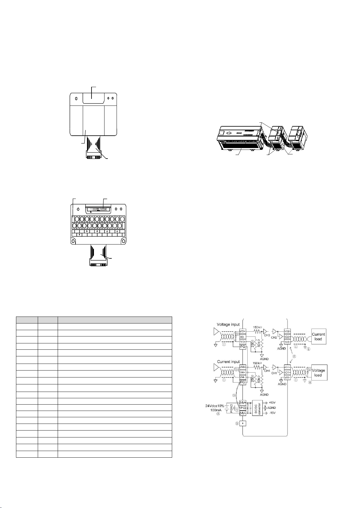
1.3 Wiring
Figure 1-4 shows the wiring of the user port. Please pay attention to the
following nine points in wiring:
1. It is recommended to use twisted screen cables as the analog input and
output cables and route them separate from power cables or other cables
that may be source of electrical interference.
2. If electric noise or voltage fluctuation is at the input/output, it is advisable to
connect a smooth capacitor (0.1µF~0.47µF/25V).
3. If there are huge amounts of electrical interference around, please connect
its FG terminal and PG terminal.
4. Each load of the PLC should be grounded separately.
5. If a channel is used for current input, please short its voltage input terminal
and current input terminal.
6. Shorting the voltage output terminals or connecting current load to the
voltage output terminals may cause damage to MC200-4AM.
7. Properly ground the module’s PG terminal.
8. The basic module’s 24Vdc auxiliary output power or external power supply
meeting requirements can be used as the power source of the module’s
analog circuit.
9. Do not use the NC terminals of the user port.
Figure 1-4 User port wiring
2
2 Use Directions
2.1 Power Specification
Table 2-1 Power specification
Item
Description
Analog circuit
24Vdc (-15%~20%), maximum allowable ripple voltage 5%,
90mA (from basic module or external power supply)
Digital circuit
5Vdc 50mA (from basic module)
2.2 Performance Specification
Table 2-2 Performance specification
Item
Specifications
I/O points occupied
None
Conversion
speed
AD conversion
speed
15ms/channel (normal speed)
8ms/channel (fastest)
DA conversion
speed
6ms/channel (max.)
Analog input
range
Voltage input
-10~10Vdc (input resistance 200kΩ), input
signal frequency<10Hz.
Warning: This module can be damaged if the
input voltage exceeds ±15Vdc
Analog input
range
Current input
-20~20mA (input resistance 250Ω), input signal
frequency<10Hz.
Warning: This module can be damaged if the
input current exceeds ±32mA
Analog output
range
Voltage output
-10~10Vdc (external load resistance not less
than 2kΩ)
Current output
0~20mA (external load resistance is 500Ω or
less)
Digital output
Default: -2000~2000
setting range: -10000~10000
Digital input
Default: -2000~2000, setting range:
-10000~10000
Resolution
Voltage input
5mV
Current input
10µA
Voltage output
5mV
Current output
10µA
Overall
accuracy
Analog input
-10V~10V, -5V~5V, -20~20mA:±1%
-100mV~100Mv:±5%
Analog output
±1% of full range
Isolation
Use optical-electric coupler for isolation
between analog circuit and digital circuit. Use
DC/DC converter for isolation between the
basic module’s power supply and external
power supply. No isolation between analog
channels
2.3 Buffer Memory (BFM)
MC200-4AM exchanges data with the basic module through BFM. The basic
module uses TO command to write data into the BFM of MC200-4AM to
configure the status of MC200-4AM. It also uses TO command to write in DA
conversion input data. It uses FROM command to read AD conversion result
and other data from the BFM of MC200-4AM.
Table 2-3 describes the contents of the BFM of MC200-4AM.
Table 2-3 BFM Contents
BFM
Contents
Remark
*#0
I/O mode selection
Default: H0000
*#1
Average sampling times of input
channel 1
Default: 8
*#2
Average sampling times of input
channel 2
Default: 8
#3
Average value of input channel 1
#4
Average value of input channel 2
#5
Current value of input channel 1
#6
Current value of input channel 2
*#7
AD conversion speed
Default: 0 (15ms/CH), high
speed (8ms/CH) if set to 1
*#8
Output data of output channel 1
Default: 0
*#9
Output data of output channel 2
Default: 0
*#10
Output channel reset command
Default: H0000
BFM
Contents
Remark
*#11
Channel characteristics setting
confirmation command
Default: H0000
*#12
Input channel 1-X0
Default: 0 (input mode 0)
*#13
Input channel 1-Y0
Default: 0 (input mode 0)
*#14
Input channel 1-X1
Default: 2000 (input mode 0)
*#15
Input channel 1-Y1
Default: 10000 (input mode 0)
*#16
Input channel 2-X0
Default: 0 (input mode 0)
*#17
Input channel 2-Y0
Default: 0 (input mode 0)
*#18
Input channel 2-X1
Default: 2000 (input mode 0)
*#19
Input channel 2-Y1
Default: 10000 (input mode 0)
*#20
Output channel 1-X0
Default: 0 (output mode 0)
*#21
Output channel 1-Y0
Default: 0 (output mode 0)
*#22
Output channel 1-X1
Default: 2000 (input mode 0)
*#23
Output channel 1-Y1
Default: 10000 (input mode 0)
*#24
Output channel 2-X0
Default: 0 (output mode 0)
*#25
Output channel 2-Y0
Default: 0 (output mode 0)
*#26
Output channel 2-X1
Default: 2000 (input mode 0)
*#27
Output channel 2-Y1
Default: 10000 (input mode 0)
#28 ~ #33
Reserved
#34
Error status
*#35
Initialization
Default: 0
*#36
Setting change enable
1 (yes), 0 (no); default: 1
#4094
Module software release
H1000
#4095
Module ID
H3222
Explanation:
1. The basic module can use TO command to write data in BFMs marked “*”
only, but it can use FROM command to read data from any BFM. When
reading from reserved BFMs, the obtained value is 0.
2. BFM#0: channel mode selection. It adopts 4 hexadecimal digits H×4×3×2×1.
Table 2-4 shows its bit status information.
Table 2-4 BFM#0 information
Bit
Value
Information
×1
0
Input range: -10V~10V
Analog
input
channel 1
1
Input range: -5V~5V, -20~20mA
2
Input range: -100mV~100mV
3
Channel closed
×2
0
Input range: -10V~10V
Analog
input
channel 2
1
Input range: -5V~5V, -20~20mA
2
Input range: -100mV~100mV
3
Channel closed
×3
0
Output mode: -10V~+10V
Analog
output
channel 1
1
Output mode: 0~20mA
2
Output mode: 4~20mA
×4
0
Output mode: -10V~+10V
Analog
output
channel 2
1
Output mode: 0~20mA
2
Output mode: 4~20mA
For example: Writing H0123 into BFM#0 makes the following settings:
Input channel 1: closed;
Input channel 2 mode: -100mV~100mV;
Output channel 1 mode: 0~20mA (note that the wiring for voltage output is
different from that for current input, see section 1.3);
Output channel 2 mode: -10V~10V;
3. BFM#1~BFM#2: average sampling times setting; setting range: 1~4096.
Default: 8, corresponding to normal speed; choose 1 if high speed is needed.
4. BFM#7: AD conversion speed setting. 0: 15ms/channel (normal speed); 1:
8ms/channel (high speed). Setting BFM#7 will restore BFM#1-#2 to the
default values, which should be noted in programming. If necessary, you can
re-set BFM#1-#2 after changing the conversion speed.
5. BFM#10: output channel reset command. When the PLC is in STOP mode,
the latest output values in RUN mode will be maintained. To reset these
values to make them become deviation values, write hexadecimal value
H×4×3×2×1into BFM#10, where ×1is the command for channel 1, ×2the
command for channel 2, ×4and ×3are meaningless. ×=1 means resetting to
deviation values.
6. BFM#11: channel characteristics setting confirmation command. After
setting the channel characteristics (from BFM#12 to BFM#27), you need to
3
write 1 into the appropriate hexadecimal data bit to validate the setting and
thereby change the channel’s output characteristics. This command will clear
automatically after being executed correctly. The format of BFM#11 is
H×4×3×2×1, Where ×1, ×2, ×3and×4are the commands for input channel 1,
input channel 2, output channel 1, and output channel 2 respectively.
7.BFM#12 to BFM#27: channel gain and deviation settings, which are set
using two-point method. X0 and X1 represent the channel’s digital output and
input respectively, Y0 and Y1 represent the channel’s analog input and
output respectively, Y0 and Y1 are in mV or µA unit, each channel occupies 4
characters. For the convenience of user setting without affecting functions,
Y0 and Y1 are respectively fixed to the analog 0 and max value. They are
user unadjustable.
Note: If the channel input is current signal ( -20mA~20mA ), the channel
mode should be set to 1. As the channel’s internal measurement is based on
voltage signal, current signals should be converted into voltage signals
(-5V~5V) by the 250Ω resistor at the current input terminal of the channel
(refer to Figure 1-4). Y1 in the channel’s characteristics setting is still in mV
unit, i.e., 5000mV ( 20mA×250Ω = 5000mV ).
For how the change in X0, Y0, X1 and Y1 affects the channel characteristics,
please refer to 3 Setting Characteristics.
8. Status information of BFM#34 is shown in Table 2-5.
Table 2-5 Status information of BFM#34
Bit of BFM#34
ON
OFF
b0: error
b1 or b2 is ON, AD/DA conversion of all
channels stopped
No error
b1: deviation,
gain error
Channel characteristics setting error in
BFM
Deviation / gain
data normal
b2: power supply
failure
24Vdc power supply failed
Power supply
normal
b3: hardware
fault
AD/DA converter or other hardware faulty
Hardware normal
b10: digital range
error
1. Digital output after AD conversion less
than –2048 or greater than +2047; 2.
Digital input for DA conversion outside
specified range
Digital input/output
value normal
b11: average
sampling times
setting error
Setting outside normal range (in this case,
the previous valid setting will be restored)
Setting within
normal range:
1~4096
9. Setting BFM#35 to 1 will restore all module settings to default values.
10. BFM#36: I/O characteristics setting change enable. Setting BFM#36 to 0
inhibits change in I/O characteristics settings. Setting it to 1 allows change in
I/O characteristics settings. The setting of BFM#36 will not change after
module restart following power restoration.
11. BFM#4094: module software release information, which can be read
using FROM command.
12. BFM#4095: module ID. ID of MC200-4AM is H3222. The user program in
PLC can use this ID to identify the module before transmitting/receiving data.
3 Setting Characteristics
3.1 Setting Input Channel Characteristics
The analog input channel characteristics of MC200-4AM is the linear
relationship between the channel’s analog input Y and digital output X. You
can set it. Each channel can be considered as the model shown in Figure 3-1.
As it is of linear characteristics, the channel characteristics can be defined by
just two points: P0 (Y0,X0) and P1 (Y1, X1), where X0 is the channel’s
digital output corresponding to analog input Y0, and X1 is the channel’s
digital output corresponding to analog input Y1.
X0
Y0 Y1
XY
P1
P0
Analog input Channel
Channel model
Digital
output
Channel characteristics setting
X1
Y(mV)
Figure 3-1 Input channel characteristics of MC200-4AM
For the convenience of use without affecting functions, Y0 and Y1 are
respectively fixed to the analog 0 and max analog value in the current mode.
That is, in Figure 3-1, Y0 is 0, Y1 is the max analog input value in the current
mode; after changing the channel mode (BFM #0), Y0 and Y1 will change
automatically according to the mode, they are user unadjustable.
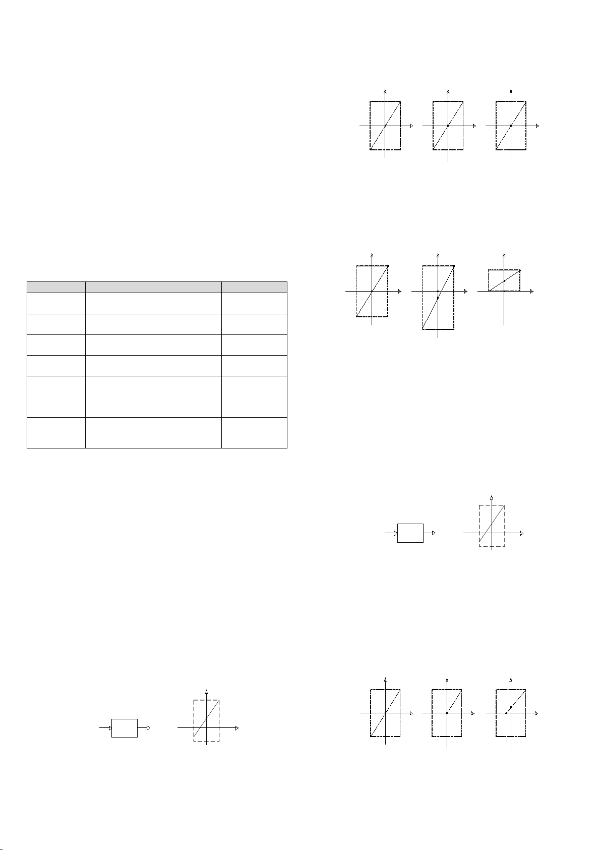
If you just set the channel mode (BFM#0) without changing the X0 and X1
values of each channel, the channel characteristics vs. mode should be as
shown in Figure 3-2. Characteristics A in Figure 3-2 shows the factory default
settings.
5000
2000
-2000
0
Y( mV)
X
-5000 100
2000
-2000
0
Y( mV)
X
-100
A. mode 0
(factory settings) B. mode 1
10000
2000
-2000
0
Y( mV)
X
-10000
C. mode 2
Figure 3-2 Characteristics vs. mode with X0 and X1 unchanged
You can change the channel characteristics by changing the X0 and X1
values. Setting ranges of X0 and X1 are both from –10000 to 10000. If the
setting is outside this range, MC200-4AM will not accept it, and just maintain
the original valid setting. Figure 3-3 gives an example of characteristics
change for your reference.
5000
2000
- 3000
0Y(mV)
X
-5000
10000
10000
-10000
0Y(mV)
X
-10000 100
1000
0
Y(mV)
X
-100
P1
P0
P1
P0
-500 1000
P1
P0
500
C. mode 2, X0=500, X1=1000
Input 100mV, corresponding to
digital ouptut 1000;
Input 0mV, corresponding to digital
ouptut 500;
Input -100mV, corresponding to
digital ouptut 0;
A. mode 0, X0=0, X1=10000
Input 10V, corresponding to
digital ouptut 10000;
Input 0V, corresponding to
digital ouptut 0;
Input -10V, corresponding to
digital ouptut -10000;
B. mode 1, X0=-500, X1=2000
Input 5V (or 20mA), corresponding to
digital ouptut 2000;
Input 1V(or 4mA), corresponding to
digital ouptut 0;
Input -5V(or -20mA), corresponding to
digital ouptut -3000;
Figure 3-3 Example of input channel characteristics change
3.2 Setting Output Channel Characteristics
The analog output channel characteristic of MC200-4AM is the linear
relationship between the channel’s analog output Y and digital input X, which
can be set by the user. Each channel can be considered as the model shown
in Figure 3-4. As it is of linear characteristics, the channel characteristics can
be defined by just two points: P0 (Y0, X0) and P1 (Y1, X1), where X0 is the
channel’s digital input corresponding to the analog output Y0, and X1 is the
channel’s digital input corresponding to the analog output Y1.
Digital input
X0
Y0
yx
P1
P0
Channel
Channel model
Analog
output
Channel characteristics setting
X1
Y( mV&mA)
Y1
X
Figure 3-4 Output channel characteristics
For the convenience of use without affecting functions, the values of Y0 and
Y1 are respectively fixed to the analog 0 and max analog value in the current
mode. That is, in Figure 3-4, Y0 is 0, and Y1 is the max analog output value in
the current mode. After changing the channel mode (BFM #0), Y0 and Y1 will
change automatically according to the mode. They are user unadjustable.
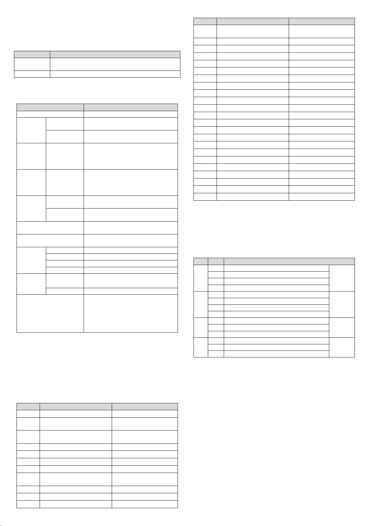
If you just set the channel mode (BFM#0) without changing the X0 and X1
values of each channel, the channel characteristics vs. mode are shown in
Figure 3-5. Characteristics A in Figure 3-1 shows the factory default settings.
20000
2000
-2000 0
Y(μA)
X
10000
2000
-2000 0
Y(mV )
X
-10000
20000
2000
-2000 0
Y(μA)
X
4000
-500
C. mode 2: 4 ~ 20 mA
A. mode 0: -10V ~ 10V
(factory settings) B. mode 1: 0 ~ 20 mA
Figure 3-5 Characteristics vs. mode with X0 and X1 unchanged
You can change the characteristics by changing the X0 and X1 values.
Setting range of X0 and X1 is from –10000 to 10000. If the setting is outside
this range, MC200-4AM will not accept it, and will just maintain the original
valid setting. Figure 3-6 gives an example of characteristics change for your

4
reference.
20000
4000
-10000 0
X
10000
10000
-10000
0
Y (mV )
X
-10000
P 0
P1
-2500 10000
P 1
P 0
Y (μA )
20000
10000
-2000 0
X
2000
P 1
P 0
Y (μA )
C. mode 2, X0=-2500, X1=10000
Input 10000, corresponding to ouptut
20mA;
Input 0, corresponding to ouptut 4mA;
Input -2500, corresponding to ouptut
0mA;
A. mode 0, X0=0, X1=10000
Input 10000, corresponding to
ouptut 10V;
Input 0V, corresponding to ouptut 0;
Input -10000, corresponding to
ouptut -10V;
B. mode 1, X0=-2000, X1=2000
Input 2000, corresponding to ouptut
20mA;
Input 0, corresponding to ouptut 10mA;
Input -2000, corresponding to ouptut
0mA;
Figure 3-6 Example of output channel characteristics change
4 Application Example
4.1 Basic Application
Example: MC200-4AM module address is 1 (for the coding of extension
modules, please refer to the MC200 Series PLC User Manual). Use its input
channels 1 and 2 for voltage signal input (-10V~10V), set the average
sampling times to 4, and use data registers D3 and D4 to receive the average
value; set output channel 1 to mode 0 and for 10V voltage signal output, and
set output channel 2 to mode 1 and for 20mA current signal output.
4.2 Changing Characteristics
Example: The MC200-4AM module address is 3 (for the coding of extension
modules, please refer to the MC200 Series PLC User Manual). Set
characteristics A in Figure 3-3 for input channel 1, and characteristics B in
Figure 3-3 for input channel 2; set their average sampling times to 4, and use
data registers D3 and D4 to receive the average value. Set characteristics A
in Figure 3-6 and 10V voltage signal output for output channel 1, and set
characteristics B in Figure 3-6 and 20mA current signal output for output
channel 2.
5 Operation Inspection
5.1 Routine Inspection
1. Check that the wiring meets requirements (refer to 1.3 Wiring).
2. Check that the extension cable of MC200-4AM is properly inserted in the
extension port.
3. Check that the 5V and 24V power supplies are not overloaded.
Note: the digital circuit of MC200-4AM is powered by the basic module
through the extension cable.
4. Check the application, make sure that the correct operation method and
parameter setting range are selected.
5. Set the MC200 basic module to RUN state.
5.2 Fault Inspection
In case of MC200-4DA malfunction, please check:
●the status of the POWER indicator
ON: the extension cable properly connected;
OFF: check the extension cable connection and the basic module.
●the wiring.
●the status of the 24V indicator
ON: 24Vdc power supply normal;
OFF: Possibly the 24Vdc power supply failed; if not, MC200-4AM is faulty.
●the status of the RUN indicator
Flash quickly: MC200-4AM in normal operation;
Flash slowly or OFF: check the data in BFM#34.
Notice
1. The warranty range is confined to the PLC only.
2. Warranty period is 18 months, within which period Megmeet Network
Power conducts free maintenance and repairing to the PLC that has any fault
or damage under the normal operation conditions.
3. The start time of warranty period is the delivery date of the product, of
which the product SN is the sole basis of judgment. PLC without a product
SN shall be regarded as out of warranty.
4. Even within 18 months, maintenance will also be charged in the following
situations:
Damages incurred to the PLC due to mis-operations, which are not in
compliance with the User Manual.
Damages incurred to the PLC due to fire, flood, abnormal voltage, etc.
Damages incurred to the PLC due to the improper use of PLC functions.
5. The service fee will be charged according to the actual costs. If there is any
contract, the contract prevails.

5
6. Please keep this paper and show this paper to the maintenance unit when
the product needs to be repaired.
7. If you have any question, please contact the distributor or our company
directly.
Shenzhen Megmeet Control Technology Co.,Ltd
Address: 5th Floor,Block B,Ziguang Information Harbor, Langshan Rd,
Science& Technology Park, Nahshan District, Shenzhen
Homepage: www.megmeet.com
All rights reserved. The contents in this document are subject to change
without notice.
Table of contents
Other Megmeet Control Unit manuals

Megmeet
Megmeet MC200-5AM User manual

Megmeet
Megmeet MC5000 Series User manual

Megmeet
Megmeet MC200-8AD User manual

Megmeet
Megmeet MC5000 Series User manual

Megmeet
Megmeet MC5000 Series User manual

Megmeet
Megmeet MC5000 Series User manual

Megmeet
Megmeet MC5000 Series User manual

Megmeet
Megmeet MC100 Series User manual
Popular Control Unit manuals by other brands


Toshiba
Toshiba ASD 9 Series manual

Rockwell Automation
Rockwell Automation Allen-Bradley MSR42 user manual

DEEP SEA ELECTRONICS
DEEP SEA ELECTRONICS DSEGenset DSE3110 Operator's manual

Rockwell Automation
Rockwell Automation Allen-Bradley 1769-BOOLEAN Reference manual

Woodward
Woodward 505XT product manual

Pololu
Pololu MC33926 user guide