manuals.online logo
Brands
  1. Home
  2. •
  3. Brands
  4. •
  5. Megmeet
  6. •
  7. Control Unit
  8. •
  9. Megmeet MC5000 Series User manual

Megmeet MC5000 Series User manual

1
IO extension module user quick
reference manual
Thank you for using MC5000 series PLC of Megmeet. Before using the
PLC product, please carefully read this booklet so as to better
understand it, fully use it, and ensure safety.This user manual is to offer
you a quick guide to the design, installation, connection and
maintenance of MC5000 series IO extension module.This quick
reference manual is used for the design, installation, connection and
maintenance of the MC5000 series IO extension module. It is
convenient for users to consult the required information on the spot, as
well as the introduction of the relevant optional accessories, FAQ, etc.,
for easy reference.
This manual for the following members:
MC5000-3200ENN
Version 1.0
Revision date Dec 15, 2018
BOM
If you need more detailed product information, please refer to MC5000
series PLC user manual ,MStart programming software user manual
and MC5000 series PLC programming reference manual issued by our
company. Consult the supplier if necessary.
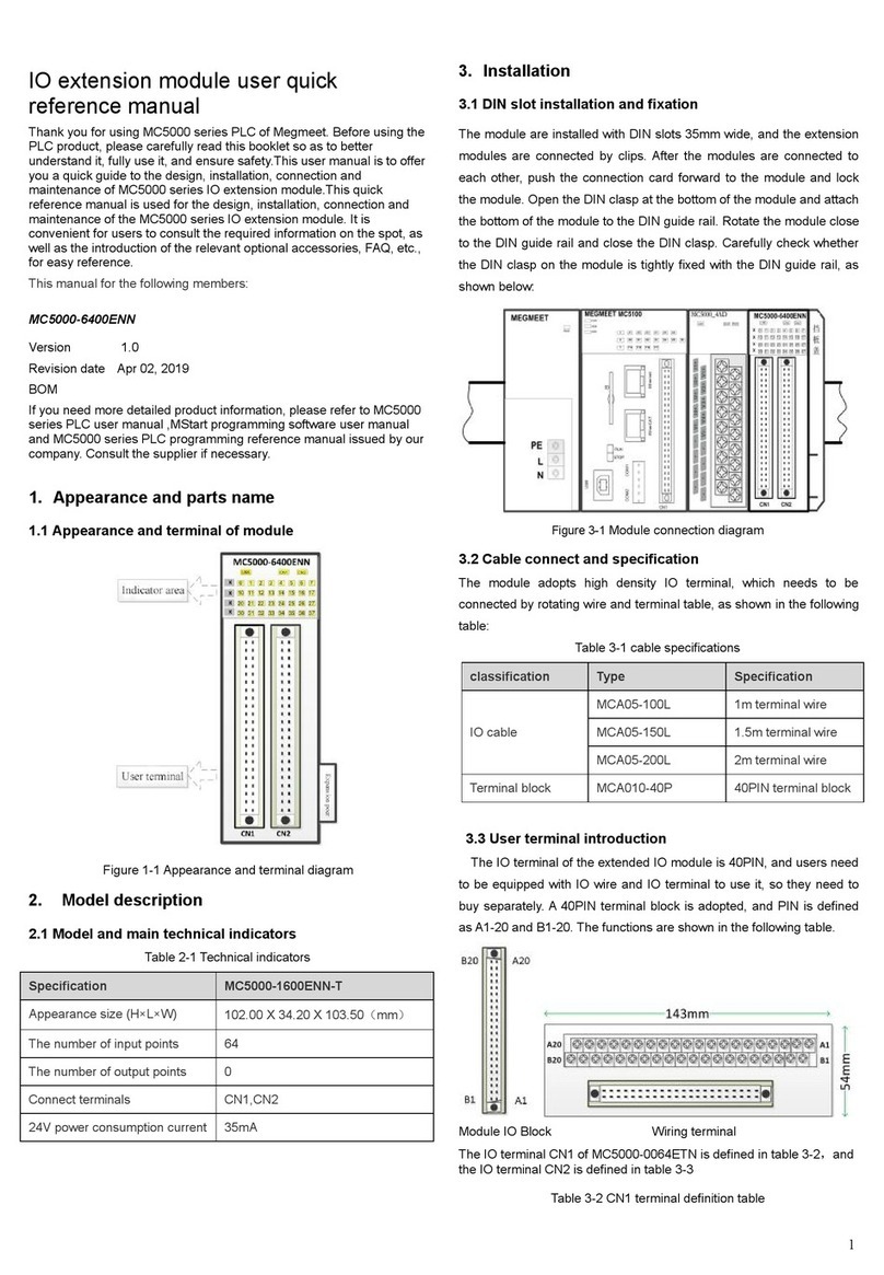
1. Appearance and parts name
1.1 Appearance and terminal of module
Figure 1-1 Appearance and terminal diagram
2. Model description
2.1 Model and main technical indicators
Table 2-1 Technical indicators
Specification
MC5000-1600ENN-T
Appearance size (H×L×W)
102.00 X 34.20 X 103.50(mm)
The number of input points
32
The number of output points
0
Connect terminals
CN1
24V power consumption current
30mA
3. Installation
3.1 DIN slot installation and fixation
The module are installed with DIN slots 35mm wide, and the extension
modules are connected by clips. After the modules are connected to
each other, push the connection card forward to the module and lock
the module. Open the DIN clasp at the bottom of the module and attach
the bottom of the module to the DIN guide rail. Rotate the module close
to the DIN guide rail and close the DIN clasp. Carefully check whether
the DIN clasp on the module is tightly fixed with the DIN guide rail, as
shown below:
Figure 3-1 Module connection diagram
3.2 Cable connect and specification
The module adopts high density IO terminal, which needs to be
connected by rotating wire and terminal table, as shown in the following
table:
Table 3-1 cable specifications
classification
Type
Specification
IO cable
MCA05-100L
1m terminal wire
MCA05-150L
1.5m terminal wire
MCA05-200L
2m terminal wire
Terminal block
MCA010-40P
40PIN terminal block
3.3 User terminal introduction
The IO terminal of the extended IO module is 40PIN, and users need
to be equipped with IO wire and IO terminal to use it, so they need to
buy separately. A 40PIN terminal block is adopted, and PIN is defined
as A1-20 and B1-20. The functions are shown in the following table.
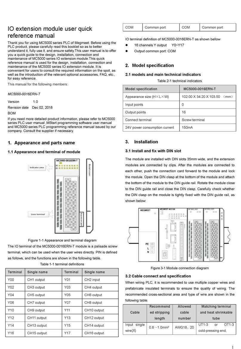
Module IO Block Wiring terminal
The IO terminal CN1 of MC5000-3200ENN is shown as below
Table 3-2 Terminal definition table
2
Function definition
Terminal screen printing
Function definition
X00
B20
A20
X10
X01
B19
A19
X11
X02
B18
A18
X12
X03
B17
A17
X13
X04
B16
A16
X14
X05
B15
A15
X15
X06
B14
A14
X16
X07
B13
A13
X17
SS0
B12
A12
SS0
/
B11
A11
/
/
B1
A10
/
X20
B9
A9
X30
X21
B8
A8
X31
X22
B7
A7
X32
X23
B6
A6
X33
X24
B5
A5
X34
X25
B4
A4
X35
X26
B3
A3
X36
X27
B2
A2
X37
SS1
B1
A1
SS1
32 channels input::
X00~X17(SS0 command terminal)
X20~X37(SS1command terminal)
3.3 Wiring instructions
Figure 3-2 Schematic diagram of internal wiring
Wiring precautions
When connecting the cables to the terminals, avoid binding them
with power lines (high-voltage lines, large currents) and other
cables that transmit strong interference signals. Route them
separately and avoid parallel routing.
It is recommended to use shielded cables to improve the
anti-interference ability.
4. Technical Parameters
4.1 Environmental index
PLC use environment temperature range: 0℃~ 55℃. When the
ambient temperature exceeds 55℃for a long time, choose a
place with good ventilation.
Places free from corrosion, flammable and explosive gases and
liquids.
A firm, vibration-free place.
This PLC is designed for the application of installing environment
II standard and pollution level 2.
4.2 Performance
Item
Technical specification
The number of input channels
32
Output connect method
Harness terminal
Input resistance
4.3KΩ
Input current
5mA
ON current/voltage
15V
OFF current/voltage
5V
Isolation method
Optocoupler isolation
Output action display
LED display
Output common
X00~X17/ SS0
X20~X37/ SS1
Filter time
0~128ms adjustable
5. Indicator definition
Table 5-1 function description table of panel indicator light
Item
Function
Troubleshooting
Lnk indicator
(yellow-green)
The status of
extension module
connect with the main
module
successful: ON
connection failed: OFF
1. Check whether the
supply voltage of the
main module is normal.
2. Check whether the
expansion clasp is
clamped tightly.
3. Check whether the
baffle cover is installed
firmly.
Input indicator
X00~X37
Each output point
corresponds to an
indicator light, which is
numbered in base 8.
3
1. Warranty scope refers to the programmable controller body.
2. The warranty period is 18 months. If the product breaks down or is
damaged during normal use, our company will repair it free of charge.
3. The warranty period starts from the date the product is manufactured.
Machine code is the only basis for judging the warranty period.
Equipment without machine code shall be treated as under warranty.
4. Even within the warranty period, a maintenance fee will be charged
if:
Failure of the machine caused by failure to operate in accordance
with the user's manual.
Damage to machinery caused by fire, flood, abnormal voltage,
etc.
Damage caused when a programmable controller is used for
abnormal functions.
Self-disassemble the programmable controller.
5. The service fee shall be calculated according to the actual cost. If
there is another contract, the contract shall take precedence.
6. If you have any questions, please contact the agent or our company
directly.
SHENZHEN MEGMEET CONTROL TECHNOLOGY CO.,LTD
Add:floor 5, tower B, qinghua information port, langshan road, north
district, science and technology park, nanshan district, shenzhen
Tel:400-6662163
Fax:(+86)0755-26897197
Zip code:518067
Web:www.megmeet.com

This manual suits for next models

1

Other Megmeet Control Unit manuals

Megmeet MC200-4AM User manual

Megmeet

Megmeet MC200-4AM User manual

Megmeet MC5000 Series User manual

Megmeet

Megmeet MC5000 Series User manual

Megmeet MC5000 Series User manual

Megmeet

Megmeet MC5000 Series User manual

Megmeet MC5000 Series User manual

Megmeet

Megmeet MC5000 Series User manual

Megmeet MC200-8AD User manual

Megmeet

Megmeet MC200-8AD User manual

Megmeet MC5000 Series User manual

Megmeet

Megmeet MC5000 Series User manual

Megmeet MC200-5AM User manual

Megmeet

Megmeet MC200-5AM User manual

Megmeet MC100 Series User manual

Megmeet

Megmeet MC100 Series User manual

Popular Control Unit manuals by other brands

EXFO IQ-3100 instruction manual

EXFO

EXFO IQ-3100 instruction manual

Watts LFM127-8 Installation, operation and maintenance

Watts

Watts LFM127-8 Installation, operation and maintenance

Balluff BNI PBS-507-001-Z011 user guide

Balluff

Balluff BNI PBS-507-001-Z011 user guide

unicore UM620 Series Hardware reference

unicore

unicore UM620 Series Hardware reference

tams elektronik HADES manual

tams elektronik

tams elektronik HADES manual

Rockwell Automation Allen-Bradley PowerFlex 750 ATEX Series user manual

Rockwell Automation

Rockwell Automation Allen-Bradley PowerFlex 750 ATEX Series user manual

Greentek VECTRA SERIES Installation and owner's guide

Greentek

Greentek VECTRA SERIES Installation and owner's guide

Schmidt MV3 Operation and maintenance manual

Schmidt

Schmidt MV3 Operation and maintenance manual

SyxthSense SFT Series Product sheet

SyxthSense

SyxthSense SFT Series Product sheet

EXFO IQS-3150 user guide

EXFO

EXFO IQS-3150 user guide

Texas Instruments FPC401 user guide

Texas Instruments

Texas Instruments FPC401 user guide

Watts 775 Series Installation, service & maintenance manual

Watts

Watts 775 Series Installation, service & maintenance manual

Festo ZSB-1/8 operating instructions

Festo

Festo ZSB-1/8 operating instructions

Vanderbilt SPCW120 installation instructions

Vanderbilt

Vanderbilt SPCW120 installation instructions

Cooper Scantronic 95 installation instructions

Cooper

Cooper Scantronic 95 installation instructions

Dräger REGARD 4208797 Installation, operation and maintenance

Dräger

Dräger REGARD 4208797 Installation, operation and maintenance

Finisar QSFP28 LR4 Application note

Finisar

Finisar QSFP28 LR4 Application note

aci EX2432D Installation & operation instructions

aci

aci EX2432D Installation & operation instructions

manuals.online logo
manuals.online logoBrands
  • About & Mission
  • Contact us
  • Privacy Policy
  • Terms and Conditions

Copyright 2025 Manuals.Online. All Rights Reserved.