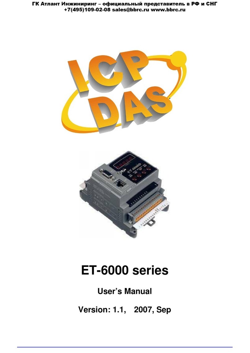
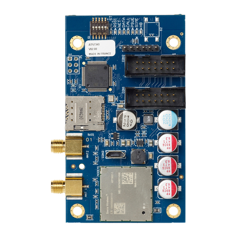
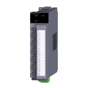
Megmeet MC5000 Series User manual

1
MC5000-4TC/8TC Temperature
Measurement Module User Manual
Thank you for using Megmeet MC5000 series PLC. Before using the
PLC product, please carefully read this booklet so as to better
understand it, fully use it, and ensure safety.This user manual is to offer
you a quick guide to the design, installation, connection and
maintenance of MC5000-4TC/8TC module, convenient for on-site
reference. Briefly introduced in this booklet are the hardware specs,
features, and usage of MC5000-4TC/8TC module, plus the optional
parts and FAQ for your reference.
This manual MC5000-4TC/8TC module for the following members:
MC5000-4TC thermocouple temperature measurement module
MC5000-8TC thermocouple temperature measurement module
Version 1.0
Revision date May 13, 2019
BOM
If you need more detailed product information, please refer to MC5000
series PLC user manual and MC5000 series PLC programming
reference manual issued by our company. Consult the supplier if
necessary.
1. Introduction
1.1 Install and fix with DIN slot
The module are installed with DIN slots 35mm wide, and the extension
modules are connected by clips. After the modules are connected to
each other, push the connection card forward to the module and lock
the module. Open the DIN clasp at the bottom of the module and attach
the bottom of the module to the DIN guide rail. Rotate the module close
to the DIN guide rail and close the DIN clasp. Carefully check whether
the DIN clasp on the module is tightly fixed with the DIN guide rail, as
shown below:
Figure 1-1 Module connection diagram
Module size (with top terminal): 103.5mm (H) ×122mm (D) ×
34mm (W)
1.2 Model and nameplate
Figure 1-2 Nameplate
Special module type:
AD: voltage and current analog input
module
DA: voltage and current analog output
module
TC:Thermocouple temperature
measurement module
PT: Thermal resistance temperature
measurement module
Number of channels:
4:4 channels
8:8 channels
MC5000 series programmable
controller
TC
MC5000
-
8
Table 1-3 Module Description
1.3 Cable connection and specifications
Cable specifications
When wiring PLC, it is recommended to use multiple copper wires and
prefabricate insulated terminals to ensure the quality of wiring. The
recommended cross-sectional area and type of wire are shown in the
following table.
Cable
Recommended
stripping
length
Allowed
cable
number
Matching terminal and
heat shrinkable tube
Input single
wire(X)
0.8~1.0mm²
AWG18、20
UT1-3 or OT1-3
cold-pressing end, Φ3
or Φ4 heat shrinkable
tube
Output
single wire
(Y)
0.8~1.0mm²
AWG18、20
Fix the machined cable head on the connection terminal of PLC with
screws. Pay attention to the correct position of the screws. The
tightening torque of the screws is between 0.5 and 0.8Nm to ensure
reliable connection without damaging the screws. The recommended
cable preparation method is shown in figure 1-4.
Figure 1-4 Cable schematic

2
1.4 Wiring requirements
For user terminal wiring requirements, see figure 1-5. In the figure①~
⑤indicates the matters that must be paid attention to when wiring:
①A thermocouple with a non-insulating tape shielding layer at the tip
can be used.
②A thermocouple with a tapered shield can be used.
③The thermocouple with no insulation and no shielding layer can be
used.
④When connecting the external cold end PT100 thermal resistance,
the wire should not be too long.
⑤The thermocouple shielding layer is well grounded.
Figure 1-5 MC5000-4tc /8TC user terminal wiring diagram
Notes for wiring:
When fixing the thermocouple cable, please do not tie the cable
together with the ac cable, the main circuit cable, the high-voltage
cable, etc., which may introduce interference and cause
measurement error.
2. Technical Parameters
2.1 Environmental index
This expansion module USES the ambient temperature range: 0℃~
55℃. When the ambient temperature exceeds 55℃for a long time,
choose a place with good ventilation.Places free from corrosion,
flammable and explosive gases and liquids.A firm, vibration-free
place.This extension module is designed for the installation of
environment II standard, pollution level 2 applications
2.2 Performance
Number of input channels
4/8CH
Sensor type
J type、K type、R type、S type、T type、
E type、N type、B type
Output model
Fahrenheit (° F), Celsius (° C)
Cold junction compensation
method
Internal / external cold junction
compensation
Resolution
24bit
Sensitivity
0.1°C,0.1℉
Accuracy
±0.2% of F.S.(@25°C±5°C)
±0.4% of F.S.(@0~50°C)
Response time
200ms/8CH
Filtering
Filter constant 0 ~ 256 adjustable,
default 8
Isolation method
Channel isolation (400VDC), analog
and digital isolation (1500VDC)
Diagnosis and protection
Overrun alarm
Slope alarm
Broken detection
2.3 Thermocouple detection type and specification
Sensor type
Celsius
temperature
range(℃)
Fahrenheit
temperature range
(℉)
K
-210~1200
-346~2192
J
-270~1370
-454~2498
R
-50~1600
-58~2912
S
-50~1600
-58~2912
T
-270~400
-454~752
E
-270~1000
-454~1832
N
-270~1200
-454~2192
B
200~1800
392~3272
3. User terminal
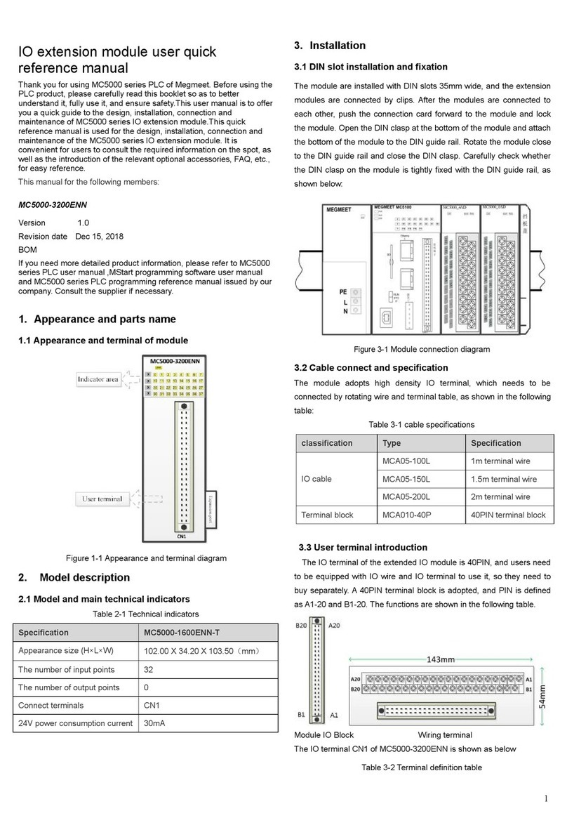
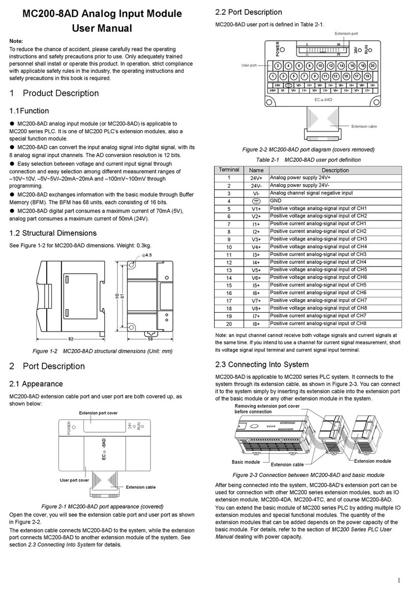
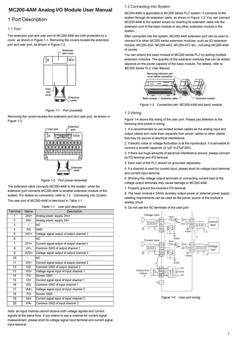
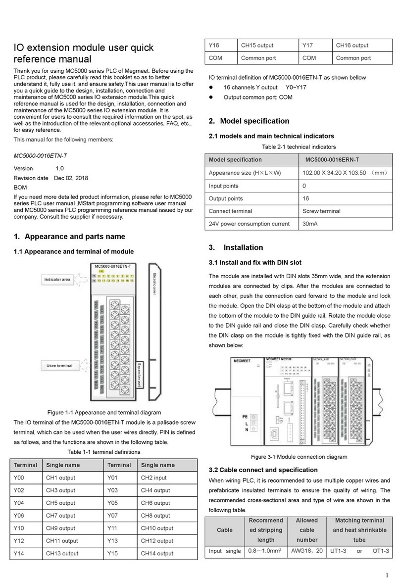
The layout of Mc5000-8tc user terminal is shown in figure 3-1, and the
definition is shown in table 3-1:
Figure 3-1 Schematic diagram of MC5000-8TC terminal block
Note: MC5000-4TC only has 1 ~ 4 channels.

3
See the following table for the definition of terminal signals:
Table 3-1 MC5000-4TC / 8TC User Terminal Definition
Terminal
Single name
INA
External cold junction PT100
INB
External cold junction PT100
L1+
The first channel thermocouple positive
L1-
The first channel thermocouple negative
L2+
The second channel thermocouple positive
L2-
The second channel thermocouple negative
L3+
The third channel thermocouple positive
L3-
The third channel thermocouple negative
L4+
Fourth channel thermocouple positive
L4-
Fourth channel thermocouple negative
L5+
Fifth channel thermocouple positive
L5-
Fifth channel thermocouple negative
L6+
Sixth channel thermocouple positive
L6-
Sixth channel thermocouple negative
L7+
Seventh channel thermocouple positive
L7-
Seventh channel thermocouple negative
L8+
Eighth channel thermocouple positive
L8-
Eighth channel thermocouple negative
.
NC
4. Diagnostic and protection functions
4.1 Panel status indicator
Table 4-1 Panel indicator function description table
Item
Function Description
Troubleshooting
LNK indicator
light
ON: the extension
module was connected
successfully
Off: extension module
connection failed
1. Check whether the supply
voltage of the main module is
normal
2. Check whether the
expansion clasp is clamped
tightly
3. Check whether the baffle
cover is installed firmly
RUN indicator
light
Flash: normally
Slow flash: module
failure or running error
See table 4-2 for the
description of the module fault
status register
ALM alarm
light
Normal operation: off
Running error: on
See table 4-3 for details on
running the error status
register
Remarks: ①Fast flashing: (5Hz flashing)
②Slow flashing: (1Hz flashing)
4.2 Module fault and error status
Table 4-2 Module fault status register
Register name
Explanation
Module fault
status (16Bit)
BIT0: Module operation error, see (Table 4-3)
Module operation error register for details
BIT4: The module parameter is wrong. For details,
please refer to (Table 4-4) Configuration
Parameter Error Register
BIT6: Temperature rate exceeds the limit
BIT8: Broken couple
BIT10: temperature exceeds the limit
Other: reserved
Table 4-3 Operation error status register
Register name
Explanation
Operate fault status
(16Bit)
BIT0: cold junction temperature
measurement overrun (-50 ℃~90 ℃)
BIT1: ADC communication is abnormal
BIT2: Reading error of internal cold
junction temperature sensor
BIT3: External FLASH read error
Other: save
Table 4-4 Description of configuration parameter errors
Register name
Explanation
Configuration parameter
error register
0: No parameter configuration error
Other: wrong parameter BFM address
4.3 Broken detection
If the temperature detection channel is open, the module will detect
whether the pair is broken. If the input is open, the module generates
an alert. The disconnected status register will be set and the ALM alarm
light will generate an alarm.
Table 4-5 description of the break state
Register name
Explanation
Overrun status register
(16Bit)
0~7bit: channel 1 ~8 broken alarm
8~15bit: reserved
4.4 Temperature limit alarm
Users can set a temperature alarm upper limit and lower limit for each
channel. When the measured temperature is higher than the upper limit
or lower than the lower limit, the channel over-limit register will be set
and the ALM light will give an alarm.
Table 4-6 Description of overrun status
Register name
Explanation
Overrun status register (16Bit)
0~7bit: channel 1 ~8 upper
alarm
8~15bit:channel 1 ~8 lower
alarm
4.5 Temperature rate alarm
The module has the function of detecting the temperature change rate
(℃/s,℉/s). When the temperature change rate exceeds the set value,
the channel temperature rate register will be set and the ALM light will
generate an alarm.
Table 4-7 Overrun state description table
Register name
Explanation
Overrun status register (16Bit)
0~7bit: channel 1 ~8
Channel 1 ~ 8 heating rate alarm
8~15bit:channel 1 ~8
Channel 1 ~ 8 cooling rate alarm
5. Operation check
1. Check whether the thermocouple wiring meets the requirements
2. Check the MC5000-4TC/8TC extension cable for reliable insertion
into the extension cable interface.
3. Check whether the module configuration and setting parameters are
correct.
4. Check whether the LINK light of Mc5000-4tc /8TC extension module
is always on and whether the RUN light flashes slowly.
6. Fault check
If the MC5000-4TC / 8TC does not operate normally, please follow the
procedure below to check.

4
1. Warranty scope refers to the programmable controller body.
2. The warranty period is 18 months. If the product breaks down or is
damaged during normal use, our company will repair it free of charge.
3. The warranty period starts from the date the product is manufactured.
Machine code is the only basis for judging the warranty period.
Equipment without machine code shall be treated as under warranty.
4. Even within the warranty period, a maintenance fee will be charged
if:
Failure of the machine caused by failure to operate in accordance
with the user's manual.
Damage to machinery caused by fire, flood, abnormal voltage,
etc.
Damage caused when a programmable controller is used for
abnormal functions.
Self-disassemble the programmable controller.
5. The service fee shall be calculated according to the actual cost. If
there is another contract, the contract shall take precedence.
6. If you have any questions, please contact the agent or our company
directly.
SHENZHEN MEGMEET CONTROL TECHNOLOGY CO.,LTD
Add:floor 5, tower B, qinghua information port, langshan road, north
district, science and technology park, nanshan district, shenzhen
Tel:400-6662163
Fax:(+86)0755-26897197
Zip code:518067
Web:www.megmeet-ia.com

5
This manual suits for next models
2
Table of contents
Other Megmeet Control Unit manuals

Megmeet
Megmeet MC5000 Series User manual

Megmeet
Megmeet MC5000 Series User manual

Megmeet
Megmeet MC200-8AD User manual

Megmeet
Megmeet MC200-5AM User manual

Megmeet
Megmeet MC100 Series User manual

Megmeet
Megmeet MC200-4AM User manual

Megmeet
Megmeet MC5000 Series User manual

Megmeet
Megmeet MC5000 Series User manual
Popular Control Unit manuals by other brands

Grundfos
Grundfos MP 204 Installation and operating instructions

Hekatron
Hekatron FSZ Pro instruction manual

Isel
Isel iPC25-F operating instructions

SMC Networks
SMC Networks VQ2000 Series Installation and maintenance manual

Velleman
Velleman Whadda WPI304 user manual

Cornelius
Cornelius Post-Mix Valves UFB-1 Installation and service manual