Megmeet MC200-8AD User manual
1
MC200-8AD Analog Input Module
User Manual
Note:
To reduce the chance of accident, please carefully read the operating
instructions and safety precautions prior to use. Only adequately trained
personnel shall install or operate this product. In operation, strict compliance
with applicable safety rules in the industry, the operating instructions and
safety precautions in this book is required.
1 Product Description
1.1Function
●MC200-8AD analog input module (or MC200-8AD) is applicable to
MC200 series PLC. It is one of MC200 PLC’s extension modules, also a
special function module.
●MC200-8AD can convert the input analog signal into digital signal, with its
8 analog signal input channels. The AD conversion resolution is 12 bits.
●Easy selection between voltage and current input signal through
connection and easy selection among different measurement ranges of
–10V~10V, –5V~5V/–20mA~20mA and –100mV~100mV through
programming.
●MC200-8AD exchanges information with the basic module through Buffer
Memory (BFM). The BFM has 68 units, each consisting of 16 bits.
●MC200-8AD digital part consumes a maximum current of 70mA (5V),
analog part consumes a maximum current of 50mA (24V).
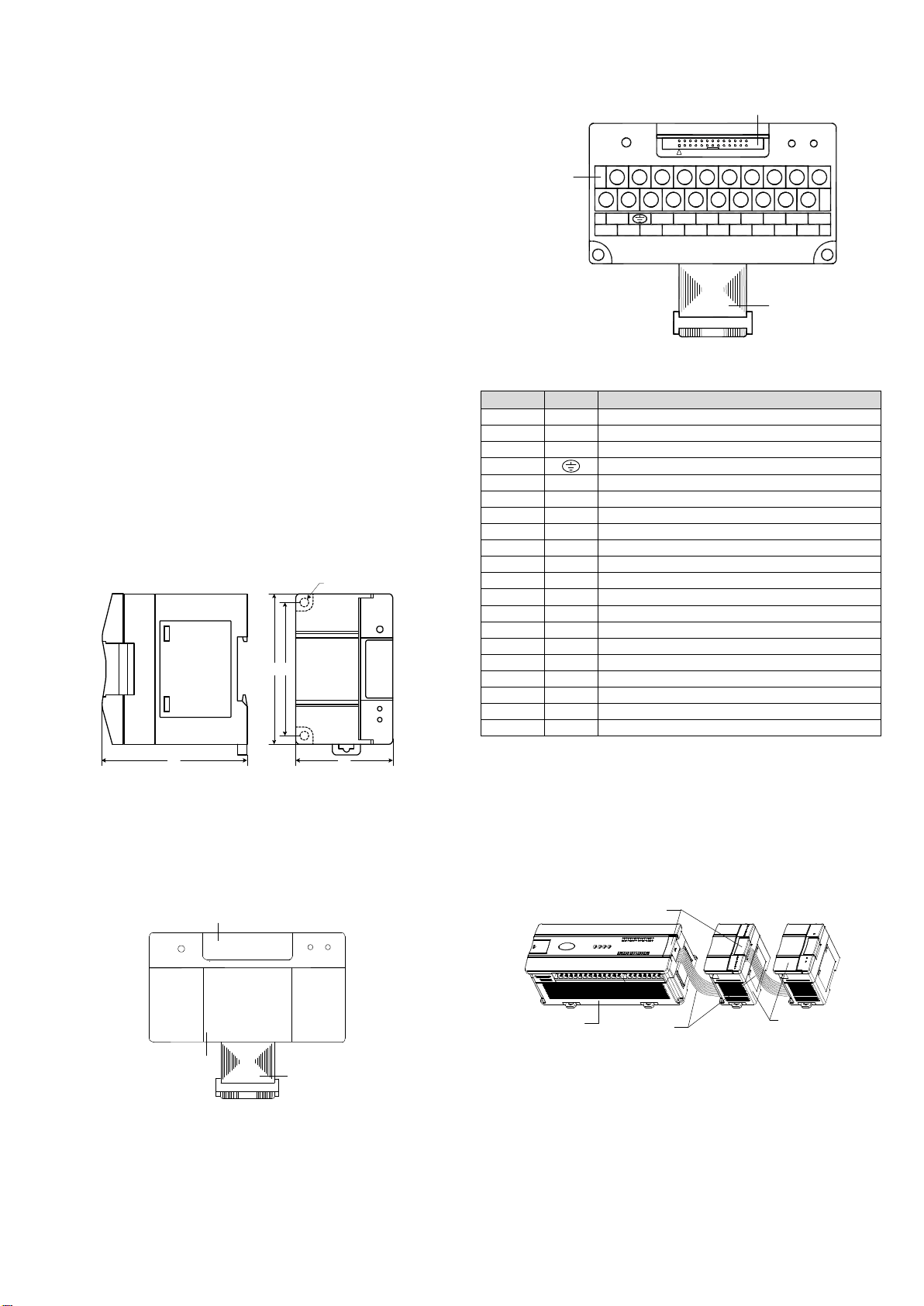
1.2 Structural Dimensions
See Figure 1-2 for MC200-8AD dimensions. Weight: 0.3kg.
90
81
58
Φ4.5
82
Figure 1-2 MC200-8AD structural dimensions (Unit: mm)
2 Port Description
2.1 Appearance
MC200-8AD extension cable port and user port are both covered up, as
shown below:
Extension cable
Extension port cover
User port cover
EC 20 -8AD
POWER
24V
RUN
Figure 2-1 MC200-8AD port appearance (covered)
Open the cover, you will see the extension cable port and user port as shown
in Figure 2-2.
The extension cable connects MC200-8AD to the system, while the extension
port connects MC200-8AD to another extension module of the system. See
section 2.3 Connecting Into System for details.
2.2 Port Description
MC200-8AD user port is defined in Table 2-1.
I2+24V-
V1+
V2+
I1+24V+ VI- V3+
V4+
I3+
I4+
V5+
V6+
I5+
I6+
V7+
V8+
I7+
I8+
Extension cable
User port
Extension port
EC 20-8AD
26
2
25
POWE R
R U N
24V
2 4 6 8 10 12 14 16 18 20
17 1913 159 115 71 3
Figure 2-2 MC200-8AD port diagram (covers removed)
Table 2-1 MC200-8AD user port definition
Terminal
Name
Description
1
24V+
Analog power supply 24V+
2
24V-
Analog power supply 24V-
3
VI-
Analog channel signal negative input
4
GND
5
V1+
Positive voltage analog-signal input of CH1
6
V2+
Positive voltage analog-signal input of CH2
7
I1+
Positive current analog-signal input of CH1
8
I2+
Positive current analog-signal input of CH2
9
V3+
Positive voltage analog-signal input of CH3
10
V4+
Positive voltage analog-signal input of CH4
11
I3+
Positive current analog-signal input of CH3
12
I4+
Positive current analog-signal input of CH4
13
V5+
Positive voltage analog-signal input of CH5
14
V6+
Positive voltage analog-signal input of CH6
15
I5+
Positive current analog-signal input of CH5
16
I6+
Positive current analog-signal input of CH6
17
V7+
Positive voltage analog-signal input of CH7
18
V8+
Positive voltage analog-signal input of CH8
19
I7+
Positive current analog-signal input of CH7
20
I8+
Positive current analog-signal input of CH8
Note: an input channel cannot receive both voltage signals and current signals at
the same time. If you intend to use a channel for current signal measurement, short
its voltage signal input terminal and current signal input terminal.
2.3 Connecting Into System
MC200-8AD is applicable to MC200 series PLC system. It connects to the
system through its extension cable, as shown in Figure 2-3. You can connect
it to the system simply by inserting its extension cable into the extension port
of the basic module or any other extension module in the system.
Basic module Extension module
Removing extension port cover
before connection
Extension cable
Figure 2-3 Connection between MC200-8AD and basic module
After being connected into the system, MC200-8AD‘s extension port can be
used for connection with other MC200 series extension modules, such as IO
extension module, MC200-4DA, MC200-4TC, and of course MC200-8AD.
You can extend the basic module of MC200 series PLC by adding multiple IO
extension modules and special functional modules. The quantity of the
extension modules that can be added depends on the power capacity of the
basic module. For details, refer to the section of MC200 Series PLC User
Manual dealing with power capacity.

2
2.4 Wiring
Figure 2-4 shows the wiring of the user port. Pay attention to the following 5
points in wiring
1. Use twisted screen cables as the analog input cables and separate them
from power cable or any cable that may generate electrical interference.
2. If the input signal fluctuates or electrical interference exists, it is advisable
to connect a smoothing capacitor (0.1µF~0.47µF/25V).
3. If a channel is used for current input, short its voltage input terminal and
current input terminal.
4. Properly ground the module’s PG terminal.
5. The basic module’s 24Vdc auxiliary output power or other qualified power
supplies can be used as the power source of the module’s analog circuit.
V1+
I1+
AGND
AGND
CH1
Voltage input
Current input
24V+
24V-
DC/DC
converter AGND
+5 V
-5 V
PG
EC20-8 AD
V8+
I8+ CH 8
VI -
①
②
③
④
150kΩ
250Ω50kΩ
150kΩ
250Ω50kΩ
DC24V(-15%~+20%)
50mA
⑤
Figure 2-4 MC200-8AD user port wiring
3 Usage
3.1 Technical Specification
The environmental parameters of MC200-8AD are the same as those of
MC200 basic module. Refer to MC200 Series PLC User Manual for details.
See Table 3-1 and Table 3-2 for other technical specification.
Table 3-1 Power specificaiton
Item
Specification
Analog circuit
24Vdc (-15%/+20%), maximum allowable ripple voltage 5%,
≤50mA (from basic module’s auxiliary power supply or external
source)
Digital circuit
5Vdc, ≤70mA (from internal power supply of the basic module)
Tabel 3-2 Performance specification
Item
Specification
Conversion speed
12ms/channel (normal speed), 4ms/channel (fastest)
Analog
input
range
Voltage input
-10V~10V, input
impedance 200kΩ
Eight channels can be used at
the same time, input range
selectable by setting BFM (see
Table 3-4 for details)
Current input
-20mA~20mA, input
impedance 250Ω
Digital output
Default: -2000~2000
Setting range: -10000~10000
Resolution
Voltage input
Depending on the input range (see Table 3-5)
Current input
10µA
Accuracy
-10V~10V, -5V~5V, -20mA~20mA: ±1%
-100mV~100mV: ±5%
Isolation
Between analog circuit and digital circuit:
optical-coupler isolation.
Between analog circuit and external power supply:
DC/DC converter isolation.
Between analog channels: no isolation
3.2 Buffer Memory
MC200-8AD exchanges data with the basic module through BFM. The basic
module uses TO command to write data into the BFM of MC200-8AD to
configure MC200-8AD, and uses FROM command to read AD conversion
result and other data from the BFM of MC200-8AD.
Table 3-3 describes the contents of the BFM of MC200-8AD.
Table 3-3 MC200-8AD BFM content
BFM
Content
Remark
Prop.
#100~
#107
Respective averages of
CH1~CH8
Respectively average values
of channels 1 ~ 8
RO
#200~
#207
Current values of CH1~CH8
Respectively current values of
channels 1~ 8
RO
#300
Error status word
RO
#400
Initialization
Default: 0
W&R
#500
Setting change enable
Default: 1 (enable)
0: disable
R&W
#600
Input mode selection 0
Default: H0000
R&W
#601
Input mode selection 1
Default: H0000
R&W
#700~
#707
Average sampling times of
channels 1 ~ 8
Defaults: 8
R&W
#800
Channel characteristics setting
confirmation command 0
Default: H0000
R&W
#801
Channel characteristics setting
confirmation command 1
Default: H0000
R&W
#900
CH1-D0
Default: 0 (input mode 0)
R&W
#901
CH1-A0
Default: 0 (input mode 0)
RO
#902
CH1-D1
Default: 2000 (input mode 0)
R&W
#903
CH1-A1
Default: 10000 (input mode 0)
RO
#904
CH2-D0
Default: 0 (input mode 0)
R&W
#905
CH2-A0
Default: 0 (input mode 0)
RO
#906
CH2-D1
Default: 2000 (input mode 0)
R&W
#907
CH2-A1
Default: 10000 (input mode 0)
RO
#908
CH3-D0
Default: 0 (input mode 0)
R&W
#909
CH3-A0
Default: 0 (input mode 0)
RO
#910
CH3-D1
Default: 2000 (input mode 0)
R&W
#911
CH3-A1
Default: 10000 (input mode 0)
RO
#912
CH4-D0
Default: 0 (input mode 0)
R&W
#913
CH4-A0
Default: 0 (input mode 0)
RO
#914
CH4-D1
Default: 2000 (input mode 0)
R&W
#915
CH4-A1
Default: 10000 (input mode 0)
RO
#916
CH5-D0
Default: 0 (input mode 0)
R&W
#917
CH5-A0
Default: 0 (input mode 0)
RO
#918
CH5-D1
Default: 2000 (input mode 0)
R&W
#919
CH5-A1
Default: 10000 (input mode 0)
RO
#920
CH6-D0
Default: 0 (input mode 0)
R&W
#921
CH6-A0
Default: 0 (input mode 0)
RO
#922
CH6-D1
Default: 2000 (input mode 0)
R&W
#923
CH6-A1
Default: 10000 (input mode 0)
RO
#924
CH7-D0
Default: 0 (input mode 0)
R&W
#925
CH7-A0
Default: 0 (input mode 0)
RO
#926
CH7-D1
Default: 2000 (input mode 0)
R&W
#927
CH7-A1
Default: 10000 (input mode 0)
RO
#928
CH8-D0
Default: 0 (input mode 0)
R&W
#929
CH8-A0
Default: 0 (input mode 0)
RO
#930
CH8-D1
Default: 2000 (input mode 0)
R&W
#931
CH8-A1
Default: 10000 (input mode 0)
RO
#1000
AD sampling speed selection
command 1
Default: 0 (12ms/CH).
1: fast (4ms/CH)
R&W
#4000
Module usage time counting
(low digit)
Default: 0
RO
#4001
Module usage time counting
(high digit)
Default: 0
RO
#4094
Module software version
H1000
RO
#4095
Module ID
H1082
RO
Note:
1. The basic module can use TO command to write data into BFMs marked
R&W only, but it can use FROM command to read data from any BFM,
including R&W and RO BFMs. When reading from reserved BFMs, the
obtained value is 0.
2. BFM#600&BFM#601: channel mode setting. These 2 are hexadecimal
figures in the format of H×4×3×2×1. In BFM#600, ×1is the setting for CH1,
×2is the setting for CH2, and so on. Whereas in BFM#601, ×1is the setting for
CH5, ×2is the setting for CH6, and so on. See the following figure:
Channel 1
4
H
600#
3
2
1
Channel 2
Channel 3
Channel 4
Channel 5
4
H
601#
3
2
1
Channel 6
Channel 7
Channel 8

3
See Table 3-4 for the meaning of “X”. When a channel is set between 3 and F
(closed), the channel will not perform A/D conversion.
Table 3-4 Meanings of X in the format
X
Status information
0
In range: -10V~10V (resolution: 5mV)
1
Input range: -5V~5V or -20mA~20mA (resolution: 2.5mV or 10µA)
2
Input range: -100mV~100mV (resolution: 0.05mV)
3-F
Channel closed
For example, if BFM #600 is set to H0123, it means that:
CH1 is closed
The input range of CH2: -100mV~100mV
The input range of CH3: -5V~5V or -20mA~20mA
The input range of CH4: -10V~10V
3. BFM#700~BFM#707: average sampling times setting. Range: 1 ~ 4096. If
the setting is outside this range, the value will be reset to the default 8. You
can select 1 for fast operation.
4. BFM#200~BFM#207: storing the current value of input data. The average
values are stored in BFM#100~BFM#107.
5. BFM#800&BFM#801: channel characteristics setting confirmation
command. After setting the channel characteristics (from BFM#900-
BFM#931), you need to write 1 into the appropriate hexadecimal data bit to
validate the setting and thereby change the channel’s output characteristics.
This command will clear automatically after being executed correctly. The
format is H×4×3×2×1, where ×1, ×2, ×3, ×4in BFM#800 are respectively the
commands for CH1, CH2, CH3 and CH4, while in BFM#801, for channels 5,
6, 7 and 8.
6.BFM#900~BFM#931: channel characteristics settings, which are set using
two-point method. D0 and D1 represent the channel’s digital outputs, while
A0 and A1, in mV unit, represent the channel’s actual inputs. Each channel
occupies 4 characters. To simplify the setting operation without affecting
functions, A0 and A1 are respectively fixed to the analog 0 and max value in
the current mode. After changing the channel mode (BFM #600ə), A0
and A1 will change automatically according to the mode. They are user
unadjustable.
Note: If the channel input is current signal (-20mA~20mA), the channel mode
should be set to 1. As the channel’s internal measurement is based on
voltage signal, current signals should be converted into voltage signals
(-5V~5V) by the 250Ω resistor at the current input terminal of the channel. A1
in the channel’s characteristics setting is still in mV unit, i.e., 5000mV
(20mA×250Ω =5000mV).
7. See Table 3-5 for the status information of BFM#300.
Table 3-5 Status information of BFM#300
Bit status of BFM#300
ON (1)
OFF (0)
b0: error
b1 or b2 is ON, AD conversion of
all channels stopped
No error
b1: channel
characteristics setting
error
Channel characteristics setting
error in BFM
Channel
characteristics
setting normal
b2: power supply failure
24Vdc power supply failed
Power supply
normal
b3: hardware fault
AD converter or other hardware
faulty
Hardware normal
b4~b9: reserved
-
-
b10: digital range error
A/D conversion digital output
exceeds the range of -2048 ~
2047
Digital output value
normal
b11: average sampling
times setting error
Setting outside normal range (in
this case, the previous valid
setting will be restored)
Setting within
normal range:
1~4096
b12~b15: reserved
-
-
8. BFM#400: Initialization command. When BFM#400 is set to 1, all module
parameters will be reset to defaults, and BFM#400 will restore to 0
automatically.
9. BFM#500: setting change enable. Setting it to 1 allows users to change the
characteristics settings. Setting it to 0 inhibits change in characteristics
settings.
10. BFM#1000: AD sampling speed selection command. Writing 1/0 into
BFM#1000 will change AD conversion speed. 0: normal speed,
12ms/channel. 1: fast, 4ms/channel.
Note that, during programming, the BFM#700~#707 will be reset to the
defaults when BFM#1000 is changed. After changing the conversion speed,
you can set BFM#700~#707 again according to the actual needs.
11. BFM#4000&BFM#4001: module’s timing information in hexadecimal
format. Unit: second.
12. BFM#4094: module software version. It can be queried through FROM
command.
13. BFM#4095: module ID. The ID of MC2008ADZ is H1082. The user
program in PLC can use this ID to identify the module before
transmitting/receiving data.
4 Setting Characteristics
The input channel characteristic of MC200-8AD is the linear relationship
between the channel’s analog input A and digital output D. It can be set by the
user. Each channel can be considered as the model shown in Figure 4-1. As
it is of linear characteristics, the channel characteristics can be defined by
just two points: P0 (A0, D0) and P1 (A1, D1), where D0 is the channel’s
digital output corresponding to analog input A0, and D1 is the channel’s
digital output corresponding to analog input A1.
Channel D
Digital output
A
Analog input
Channel model
D1
A(0.1℃)
Channel characteristic setting
D0
A0 A1
P1
P0
D(0.1℃)
Figure 4-1 Channel characteristics of MC200-8AD
To simplify the operation process without affecting functions, A0 and A1 are
respectively fixed to the analog 0 and max analog value in the current mode.
That is to say, in Figure 3-1, A0 is 0 and A1 is the max analog input value in
the current mode. After changing the channel mode (BFM #600ə), A0
and A1 will change automatically according to the mode. Users cannot
change their values.
If you just set the channel mode (BFM#600ə) without changing the D0
and D1 values of each channel, the channel characteristics vs. mode should
be as shown in Figure 4-2. Characteristics A in Figure 4-2 shows the factory
default settings.
D
2000
-10000 10000
- 2000
A(mV)
0
A Mode 0 (default)
D
2000
-100 100
- 2000
A (mV)
0
C Mode 2
B Mode 1
D
2000
- 5000 5000
- 2000
A( mV)
0
Figure 4-2 Characteristics vs. mode with D0 and D1 unchanged
You can change the channel characteristics by changing D0 and D1. Setting
ranges of D0 and D1 are both from -10000 to 10000. If the setting is outside
this range, MC200-8AD will not accept it, and just maintain the original valid
setting. Figure 4-3 gives an example of characteristic change for your
reference.
D
1000
-100 100
A ( mV )
0
500 P 0
P1
C. Mode 2, D0=500, D1=1000
Input 100mA: output digital signal 1000
Input 0mA: output digital signal 500
Input -100mA: output digital signal 0
D
2000
-5000 5000
-3000
A(mV )
0
P0
P1
-500 1000
B. Mode 1, D0=-500, D1=2000
Input 5V(or 20mA): output digital signal 2000
Input 1V(or 4mA): output digital signal 0
Input -5V(or -20mA): output digital signal -3000
D
10000
-10000 10000
-10000
A ( mV )
0
P0
P1
A. Mode 0, D=0,D1=1000
Input 10V: output digital signal 10000
Input 0V: output digital signal 0
Input -10V: output digital signal -10000
Figure 4-3 Changing characteristics
4
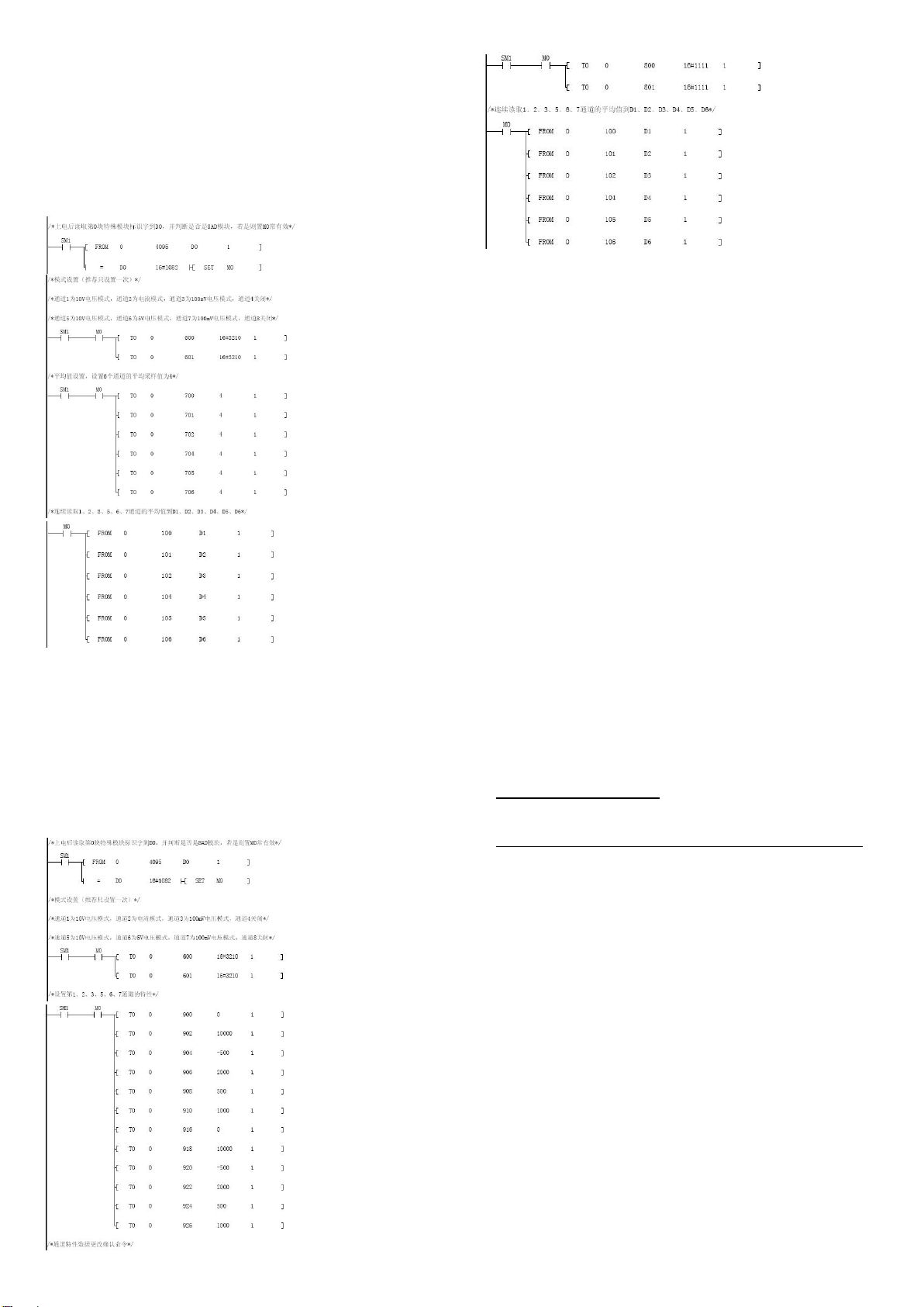
5 Application Example
5.1 Basic Application
Example: MC200-8AD module address is 0. Use channels 1 and 3 for voltage
signal input of respectively -10V~10V and –100mV~100mV and CH2 for
current signal input (-20mA~20mA). Close CH4. Use channels 5, 6 and 7 for
voltage signal input of respectively -10V~10V, -5V~5V and -100mV~100mV
and close CH8. Set the average sampling times to 4, and use data registers
D1, D2, D4, D5 and D6 to receive the converted average value.
5.2 Changing Characteristics
Example: The MC200-8AD module address is 0. Use channels 1 and 3 for
voltage signal input of respectively -10V~10V and -100mV~100mV and CH2
for current signal input (-20mA~20mA). Close CH4. Use channels 5, 6 and 7
for voltage signal input of respectively -10V~10V, -5V~5V and
-100mV~100mV and close CH8. The following example will realize the
characteristic change as shown in Figure 4-3: channels 1 and 5 realize
characteristic A, channels 2 and 6 realize characteristic B, channels 3 and 7
realizes characteristic C. Channels 4 and 8 are closed. Use data registers D1
to D6 to receive the converted averages.
6 Operation Inspection
6.1 Routine Inspection
1. Check that the wiring meets requirements (refer to section 2.4 Wiring).
2. Check that the extension cable of MC200-8AD is properly connected to the
extension port.
3. Check that the 5V and 24V power supplies are not overloaded. Note: the
digital circuit of MC200-8AD is powered by the basic module through the
extension cable.
4. Check the application, make sure that the correct operation method and
parameter setting range are selected.
5. Set the MC200 basic module to RUN state.
6.2 Fault Inspection
In case of MC200-8DA malfunction, check the following items.
●the POWER indicator
ON: the extension cable properly connected
OFF: check the extension cable connection and the basic module
●the wiring
●the 24V indicator
ON: 24Vdc power supply normal;
OFF: either 24Vdc power supply faulty, or MC200-8AD faulty
●the RUN indicator
Flashing quickly: MC200-8AD normal
Off or flashing slowly: check BFM#34
Notice
1. The warranty range is confined to the PLC only.
2. Warranty period is 18 months, within which period Megmeet Network
Power conducts free maintenance and repairing to the PLC that has any fault
or damage under the normal operation conditions.
3. The start time of warranty period is the delivery date of the product, of
which the product SN is the sole basis of judgment. PLC without a product
SN shall be regarded as out of warranty.
4. Even within 18 months, maintenance will also be charged in the following
situations:
Damages incurred to the PLC due to mis-operations, which are not in
compliance with the User Manual;
Damages incurred to the PLC due to fire, flood, abnormal voltage, etc;
Damages incurred to the PLC due to the improper use of PLC
functions.
5. The service fee will be charged according to the actual costs. If there is any
contract, the contract prevails.
6. Please keep this paper and show this paper to the maintenance unit when
the product needs to be repaired.
7. If you have any question, please contact the distributor or our company
directly
Shenzhen Megmeet Control Technology Co.,Ltd
Address: 5th Floor,Block B,Ziguang Information Harbor, Langshan Rd,
Science& Technology Park, Nahshan District, Shenzhen
Homepage: www.megmeet.com
All rights reserved. The contents in this document are subject to change
without notice.
Other Megmeet Control Unit manuals

Megmeet
Megmeet MC5000 Series User manual

Megmeet
Megmeet MC5000 Series User manual

Megmeet
Megmeet MC5000 Series User manual

Megmeet
Megmeet MC5000 Series User manual

Megmeet
Megmeet MC5000 Series User manual

Megmeet
Megmeet MC200-5AM User manual

Megmeet
Megmeet MC200-4AM User manual

Megmeet
Megmeet MC100 Series User manual


