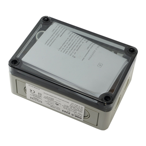
VITECTOR FRABA OSE-C 1001 User manual

O R I G I N A L B E T R I E B S A N L E I T U N G – O S E - C 1 0 0 1
Ausgabe: 2012-05-31 VITECTOR GmbH 1 / 6
Carlswerkstr. 13c, D - 51063 Köln
Tel.: +49 (0) 221 - 9 62 13-0, Telefax +49 (0) 221 - 9 62 13-60, www.vitector.de, info@vitector.de
D
Gültigkeitsbereich
Diese Betriebsanleitung gilt für die externe
Auswerteeinheit OSE-C 1001 Version 3.0, in Verbindung
mit OSE Schaltleisten.
Beschreibung
Die externe Auswerteeinheit OSE-C 1001 wurde
entwickelt nach den Anforderungen:
- Sicherheitskategorie 2 nach DIN EN ISO 13849-1
- Performancelevel c nach DIN EN ISO 13849-1
Sie kann damit entsprechend den Normen DIN EN 12453
und EN 12978 für Tore eingesetzt werden in denen eine
Testung der Sicherheitsschaltleiste vor Einleiten der
Torfahrt erfolgt.
Eine Verwendung zum Personenschutz ist ohne Testung
gemäß EN 13241-1 und EN 12453 nicht zulässig.
Ausgangs-Relaiskontakt
Der sicherheitsgerichtete Ausgangs-Relaiskontakt
(Klemmen NC/COM) öffnet, wenn die
Sicherheitsschaltleiste betätigt wird.
Für nicht sicherheitsgerichtete Anwendungen ist der
Anschluss als Schließer (Klemmen NO/COM) möglich,
dieser Kontakt schließt, wenn die Sicherheitsschaltleiste
betätigt wird.
Interner Test
Die OSE-C 1001 ist für den Test durch eine Torsteuerung
vorgesehen. Der Test geschieht bevorzugt in der Position
„Tor Auf“, da der Ausgangskontakt während des Tests
anspricht. Die Torsteuerung muss für min. 50 ms das
Testsignal aktivieren. Bei erfolgreichem Test wird der
Ausgangskontakt betätigt, was von der Torsteuerung
entsprechend ausgewertet werden muss.
Gehäusemontage
Das Gehäuse kann mit zwei Schrauben auf jedem
ebenen, schwingungsfreien Untergrund montiert werden.
Dank der variablen Kabeleingänge kann die Auswertung
sowohl auf dem Torblatt als auch stationär als
Abzweigdose des Spiralkabels genutzt werden.
Sicherheitsbestimmungen
-Das Sicherheitsschaltgerät darf nur von Personen
installiert und in Betrieb genommen werden, die mit
dieser Bedienungsanleitung, der Benutzerinformation,
den geltenden Vorschriften über Arbeitssicherheit,
Unfallverhütung, VDE- und die örtlichen Vorschriften
(Schutzmaßnahmen) vertraut sind. Die
Gesamtsicherheit von Maschine und
Schutzeinrichtung ist von der Zuverlässigkeit der
dazwischenliegenden Schnittstelle abhängig.
-Erschütterungen, die größer als 5 g/33 Hz sind (VDE
0160) sind zu vermeiden.
-Austausch und Verwendung von nicht vom Hersteller
zugelassenen Komponenten kann die Funktion der
Einrichtung beeinträchtigen. Durch Öffnen des
Gehäuses, eigenmächtige Umbauten erlischt jegliche
Gewährleistung.
-Nur für Kleinspannungsversorgung, es besteht keine
sichere Trennung von Ein- und Ausgängen nach DIN
VDE 0110 Teil 1!
Instandhaltung
Die Schaltleiste muss einmal jährlich mit einer optischen
Sichtprüfung auf Beschädigung kontrolliert werden. Bei
Beschädigung muss die Schaltleiste getauscht werden
weil die Sicherheitswirkung nicht mehr vollständig
gewährleistet ist. Es müssen die folgenden Kontrollen
durchgeführt werden:
-Überprüfung des Gummiprofils auf Beschädigung z.B.
Risse
-Überprüfung des Gummiprofils auf zu geringe
Elastizität wegen z.B. Alterung
-Überprüfung auf festen Sitz der Befestigung
-Auslösen der Schaltleiste durch Betätigung des
Gummiprofils per Hand

O R I G I N A L B E T R I E B S A N L E I T U N G – O S E - C 1 0 0 1
Ausgabe: 2012-05-31 VITECTOR GmbH 2 / 6
Carlswerkstr. 13c, D - 51063 Köln
Tel.: +49 (0) 221 - 9 62 13-0, Telefax +49 (0) 221 - 9 62 13-60, www.vitector.de, info@vitector.de
D
Klemmenbelegung
Klemmenbezeichnung
Funktion
+ - 24 V AC/DC Versorgungsspannung (Bei DC Versorgung Polarität + und – beachten)
Test Testeingang
NC Sicherheitsausgang, öffnet bei Betätigung der Sicherheitskontaktleiste
COM Gemeinsamer Ausgangskontakt zu NC und NO
NO Nicht sicherheitsgerichteter Ausgang, schließt bei Betätigung der Sicherheitskontaktleiste
bn 12 V – Spannungsversorgung für OSE Sender- und Empfängereinheit (braune Leitung)
wh 0 V – Versorgung für OSE Sender- und Empfängereinheit (weiße Leitung)
gn Signalleitung für Anschluss der OSE-Leiste (grüne Leitung)
Anschlussschema
GN
www.vitector.com
OSE
Test
BNWH
24V
NO
NC
OSE-C 1001-V3.0
Com
AC/DC
Hi
Low
Test
- 24V +
TEST
< 0,5 A
Jumper „Test“
Kontakt
Funktion
Hi Testung High Aktiv
Low Testung Low Aktiv
Hi
T
e
s
t
T
e
s
t
Low
GND
GND
+24V
+24V
Test Signal
Anzeige
Leuchtdiode
Funktionsanzeige
OSE Sicherheitskontaktleiste in Ordnung
Betriebszustände/Fehleranalyse/Störbehebung
Anzeige
Betriebsz
u
stand
Mögliche Ursachen
Abhilfe
LED "OSE" leuchtet In Ordnung
LED "OSE" leuchtet nicht Nicht bereit Spannungsversorgung defekt oder
verpolt
Spannungsversorgung überprüfen
Testeingang nicht angeschlossen
oder Jumper „Test“ falsch gesteckt
Test Eingang mit Testsignal der
Steuerung verbinden, ggf. Jumper
umstecken
Sicherheitskontaktleiste OSE defekt Verkabelung der OSE überprüfen

O R I G I N A L B E T R I E B S A N L E I T U N G – O S E - C 1 0 0 1
Ausgabe: 2012-05-31 VITECTOR GmbH 3 / 6
Carlswerkstr. 13c, D - 51063 Köln
Tel.: +49 (0) 221 - 9 62 13-0, Telefax +49 (0) 221 - 9 62 13-60, www.vitector.de, info@vitector.de
D
Sicherheitskenngrößen
Die Sicherheitskenngrößen gelten nur für den sicherheitsgerichteten Kontakt NC/COM. Der Kontakt NO/COM besitzt
keine Sicherheitskategorie. Die Sicherheitskenngrößen gelten für die Kombination aus
OSE-C 1001, OSE-T 1100, OSE-R 1100 bzw. OSE-C 1001, OSE-T 6521, OSE-R 6501. Sie beinhalten keine Angaben
des Gummihohlprofils.
Sicherheitskategorie 2 (EN 13849-1:2008)
Performance Level c (EN 13849-1:2008)
Max. Gebrauchsdauer (T
M
) 20 Jahre
MTTFd *) 47 Jahre
PFH *) 3 x 10
-
7
pro Stunde
DCav 90 %
Reaktionszeit 16 ms
*) gilt für B
10d
= 2 x 10
5
und N
op
≤4 pro Stunde
Allgemeine Technische Daten
Schutzart IP 65 (DIN VDE 0470)
Gehäusematerial ABS, hellgrau ähnlich. RAL 7035
Gehäusemaße Breite, Höhe, Länge: 48,5 x 40 x 90 mm (ohne Kabelverschraubungen)
Zul. Gebrauchslage Beliebig
Einsatztemperatur -20 °C bis +55 °C
Versorgungsspannung 24 V DC ±20%
24 V AC +5/-35% 48-64 Hz
Leistungsaufnahme max. 2,5 W
Testung Zeit bis Abschalten: < 50 ms
Testung aktiv: 0 V, max. 1 V
Funktion freigeben: 24 V, +/- 20 %
Relais Daten
Ausgang NC/COM und NO/COM
Schaltspannung max. 120 V AC / 60 V DC ohmsche Last
Schaltstrom max. 0,5 A, 120 V AC / 1 A, 24 V DC
Schaltstrom min. 1 mA, 1 VDC
Absicherung 0,5 A träge (nicht im Gerät enthalten)
Sicherheitshinweis
Öffnen des Gehäuses nur durch unterwiesenes Personal
Spannungsführende Teile

C O P Y O F O R I G I N A L M A N U A L – O S E - C 1 0 0 1
Release: 2012-06-04 VITECTOR GmbH 4 / 6
Carlswerkstr. 13c, D - 51063 Köln
Tel.: +49 (0) 221 - 9 62 13-0, Telefax +49 (0) 221 - 9 62 13-60, www.vitector.de, info@vitector.de
GB
Scope
This manual is intended for the external control unit
OSE-C 1001 (24V), in combination with an OSE- safety
edge.
Description
The external control unit OSE-C 1001 has been devel-
oped according to the requirements:
- Safety category 2 (DIN EN ISO 13849-1)
- Performance level c (DIN EN ISO 13849-1)
Because of that it can be used in accordance with
DIN EN 12453 and EN 12978, at doors where the safety
edge is tested before every door cycle.
Any use for personal protection in systems without testing
according to EN 13241-1 and EN 12453 is not allowed.
Output Relay Contacts
The safety-related contact of the output-relay
(clamp NC/COM) opens when the safety edge is actuat-
ed. For not safety-related applications the normally open
contact (clamp NO/COM) can be used. It is closed when
the safety edge is actuated.
Internal Test
The OSE-C 1001 is scheduled to be tested by the door
control. The test is done preferential when the door is
open because the output contact will be switched. For
testing the door control has to activate the test signal for
at least 50 ms. If the test is successful the output contact
will be activated, this has to be evaluated by the door
control.
Housing assembly
The Housing can be fixed with two screws on every plane,
vibration-free underground. Due to the variable cable
length the OSE-C 1001 can be fixed on the door leaf as
well as stationary as a junction box for the spiral cable.
Safety regulations
-The unit should be installed and operated by persons,
who are familiar with these instructions and the current
regulations for safety at work and accident prevention.
Follow local regulations especially as regards preven-
tative measures. Safety level of machine and safety
equipment depends on reliability of the used interface.
-Avoid mechanical vibrations greater than 5 g/33 Hz
(VDE 0160).
-Replacement and use of components, which are not
certified by the producer, may cause safety risk. Any
guarantee is void following opening of the housing or
unauthorized modifications.
Only for low voltage supply, there is no safe separation
between In- and Output contacts in according to
DIN VDE 0110 Part 1!
Maintenance
The safety edge shall be tested yearly by optical inspec-
tion concerning defects. In case of any defect the safety
edge shall be changed because the safety function is not
guaranteed completely. The following inspections shall be
done:
-Inspection of the rubber profile concerning defects e.g.
cracks
-Inspection of the rubber profile concerning decreased
elasticity e.g. due to aging
-Inspection of a close mounted seat
-Triggering of the safety edge by hand obstructing the
rubber profile

C O P Y O F O R I G I N A L M A N U A L – O S E - C 1 0 0 1
Release: 2012-06-04 VITECTOR GmbH 5 / 6
Carlswerkstr. 13c, D - 51063 Köln
Tel.: +49 (0) 221 - 9 62 13-0, Telefax +49 (0) 221 - 9 62 13-60, www.vitector.de, info@vitector.de
GB
Hi
T
e
s
t
T
e
s
t
Low
GND
GND
+24V
+24V
Test Signal
Terminal assignment
Terminal designation Function
+ - 24 V AC/DC Power supply (when supplied with DC note polarity + and -)
Test Input for test signal
NC Safety-related output, is opened when safety edge is activated
COM Common contact for NO and NC output
NO Non safety-related contact, is closed when safety edge is activated
bn 12 V – supply voltage of the OSE Transmitter and Receiver (brown cable)
wh 0 V – supply voltage of the OSE Transmitter and Receiver (white cable)
gn Signal Input for Transmitter and Receiver (green cable)
Wiring Diagram
GN
www.vitector.com
OSE
Test
BNWH
24V
NO
NC
OSE-C 1001-V3.0
Com
AC/DC
Hi
Low
Test
- 24V +
TEST
< 0,5 A
Indication LED
LED Function display
OSE Safety Edge is Ok
Operating status, fault diagnosis, trouble-shooting
Indication
Operating status
Possible cause
Remedy
LED “OSE” lights All is right
LED “OSE” is not lit Not ready Supply voltage defective or
polarity is wrong
Check supply voltage
No Test input connected or
Jumper “test” connected wrong
Connect Test input with test signal of control unit,
possibly switch jumper
Safety edge OSE defective Check wiring of OSE safety edge
Jumper „Test“
Contact
Fun
c
tion
Hi Test is High Activ
Low Test is Low Activ

C O P Y O F O R I G I N A L M A N U A L – O S E - C 1 0 0 1
Release: 2012-06-04 VITECTOR GmbH 6 / 6
Carlswerkstr. 13c, D - 51063 Köln
Tel.: +49 (0) 221 - 9 62 13-0, Telefax +49 (0) 221 - 9 62 13-60, www.vitector.de, info@vitector.de
GB
Safety Properties
The safety properties are valid for the safety-related contacts (NC/COM). The non safety-related (NO/COM) does not
contain any safety category. The safety properties are valid for the combination of
OSE-C 1001, OSE-T 1100, OSE-R 1100 and OSE-C 1001, OSE-T 6521, OSE-R 6501. They do not include values of the
rubber profile.
Category 2 (EN 13849-1:2008)
Performance level c (EN 13849-1:2008)
Maximum usage duration 20 years
MTTFd *) 47 years
PFH *) 3 x 10
-
7
per hour
DC 90 %
Reaction time 16 ms
*) valid for B
10d
= 2 x 10
5
and N
op
≤4 per hour
General Technical Data
Protection class IP 65 (DIN VDE 0470)
Housing material ABS, light grey similar. RAL 7035
Dimensions width, high, lenght: 48,5 x 40 x 90 mm (without cable gland)
Operation position any
Operating temperature -20 °C to +55 °C
Supply voltage 24 V DC ±20%
24 V AC +5/-35% 48-64 Hz
Power consumption max. 2,5 W
Testing Time to switch: < 50 ms
Test activ: 0 V, max. 1 V
Function enabled: 24 V, +/- 20 %
Relay data
Output
NC/COM
and
NO/COM
Switching voltage max. 120 V AC / 60 V DC ohmsche Last
Switching current max. 0,5 A, 120 V AC / 1 A, 24 V DC
Switching current min. 1 mA, 1 VDC
Fusing 0,5 A slow blowing (not part of unit)
Security advice
Only instructed persons are allowed to open the housing!
High voltage inside!
Table of contents
Languages:
Other VITECTOR FRABA Control Unit manuals
Popular Control Unit manuals by other brands

Graco
Graco 222461 Instructions-parts list

Dixon Bayco
Dixon Bayco 2180 Maintenance & Operating Instructions
CLA-VAL
CLA-VAL 50-01 Installation, operation and maintenance
Bevent Rasch
Bevent Rasch Fenix 2 manual
Honeywell
Honeywell JADE W7220 installation instructions
Bosch
Bosch Control 8313 Service instructions for contractors
