MEHEN M10C User manual
PLEASE WELL READ THIS MANUAL BEFORE USE
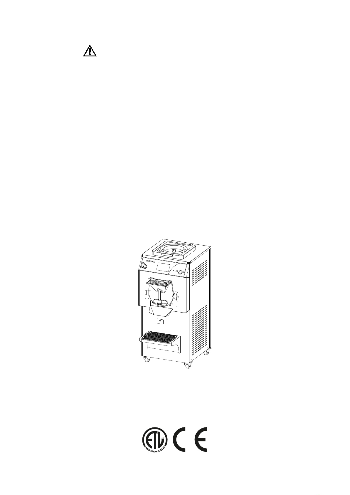
HEAT-FREEZE COMBINATION MACHINE
M10C
M15C
M20C
M30C
Version 4.6

- 2 -
On behalf of MEHEN, we hereby wish to express our sincerely thanks for
purchasing MEHEN machines.
MEHEN Machines are in conformity with EU Directive(s):
Machinery Directive: 2006/42/EC
Electromagnetic Compatibility Directive: 2004/108/EC
Food processing machinery — Basic concepts —Part 2: Hygiene requirements: EN
1672-2:2005+A1:2009
Electrical Equipment of Industrial machines: EN60204-1:2006+A1:2009
Immunity for industrial environments: EN61000-6-2:2005
Emissions for Industrial environments: EN61000-6-4:2007
Some models comply with the requirements of the Standard(s) for Special Purpose
Food Equipment & Devices (NSF-169) and are identified with the ETL Sanitation
Listed Mark.
_________________________________________________________________________
MEHEN FOOD MACHINE MANUFACTURE CO., LTD.
Xin Ling North Rd 1, ChunHua Street, Jiangning District, Nanjing, 211123,
P.R.CHINA Tel. 0086-25.68552699 Fax. 0086-25-68901895
_________________________________________________________________________
This handbook may neither be reprinted, reproduced, transferred for any
commercial purposes, nor translated in other languages unless agreed by MEHEN
in advance.
The purchasers are allowed to reprint or copy the handbook for own official use.
Provided that MEHEN's new products are upgraded with new model or new
design, MEHEN reserves the rights to make amendments and revisions when
necessary without making notice to the purchasers.
Product design and specifications are subject to change without notice. This
includes primary product specifications, controller and this manual.
The manufacturer assumes no liability for any errors or discrepancies in this
manual.

- 3 -
INDEX
FOREWORD
Handbook Instructions...............................................................................................
Symbol Annotation......................................................................................................
CHAPTER 1 GENERAL INFORMATION
1.1 Nameplate of Machine........................................................................................
1.2 Machine Layout...................................................................................................
1.3 Working Conditions............................................................................................
CHAPTER 2 INSTALLATION
2.1 Position..................................................................................................................
2.2 Room Condition....................................................................................................
2.3 Installation of Air-cooled Machine......................................................................
2.4 Installation of Water-cooled Machine...............................................................
2.5 Electrical Connection..........................................................................................
2.6 Change Cable.......................................................................................................
2.7 Refrigerant Gas Refill..........................................................................................
2.8 Machine Testing..................................................................................................
2.8.1 Check the Rotation Direction of Agitator............................................
2.8.2 Running Test of Freezer........................................................................
2.8.3 Running Test of Cooker.........................................................................
CHAPTER 3 EXPLOSION DIAGRAM
3.1 Components Position ...........................................................................................
3.2 Freezer Driving Parts Diagram.........................................................................
3.3 Freezer Blender Diagram..................................................................................
3.4 Freezing Cylinder Door Diagram.......................................................................
3.5 Valve Driving Parts Diagram.............................................................................
3.6 Cooker Blender Diagram....................................................................................
CHAPTER 4 CONTROLS AND OPERATION
4.1 Freezer Cylinder Door Operation.....................................................................
4.2 Transfer the Hot Mix From Boiler to Freezer Cylinder.................................
4.3 Electrical Control Panel.......................................................................................
4.4 Common Operations..........................................................................................
4.4.1 Language Setting.....................................................................................
4.4.2 Date and Time setting.............................................................................
4.4.3 Controller Initialization............................................................................
4.5 Freezer Operation.................................................................................................
4.5.1 Freezer Daily Operation..........................................................................
4.5.2 Freezer Producing Programs..................................................................
4.5.2.1 Hardness Mode..............................................................................
4.5.2.2 Time Mode....................................................................................
6
6
7
7
7
8
8
8
8
9
9
9
9
9
10
10
11
12
12
13
13
14
14
15
15
15
15
16
16
17
17
17
17
18

- 4 -
4.5.2.3 Temperature Mode.................................................................................
4.5.2.4 Granita Mode......................................................................................
4.5.3 Freezer Program Setting..................................................................................
4.5.3.1 How to Set Freezer Program?........................................................
4.5.3.2 Freezer Programs Setting.................................................................
4.5.4 Freezer User Parameters Setting.............................................................
4.5.4.1 How to Set Freezer User Parameters?................................................
4.5.4.2 Freezer User Parameter List................................................................
4.5.5 Freezer Take Out the Product.................................................................
4.5.5.1 Normal Take Out.............................................................................
4.5.5.2 Filling Cups Take Out......................................................................
4.5.6 Clean the Cylinder.......................................................................................
4.5.7 Door Open.....................................................................................................
4.5.8 Compressor Overtime...............................................................................
4.5.9 Error Alarm.................................................................................................
4.5.10 Operation With Error................................................................................
4.5.11 A Typical Freezer Producing Operation................................................
4.6 Cooker Operation.................................................................................................
4.6.1 Cooker Daily Operation............................................................................
4.6.2 Cooker Producing Programs...................................................................
4.6.3 Cooker Program Setting...........................................................................
4.6.3.1 How to Set Cooker Program?.......................................................
4.6.3.2 Cooker Programs Setting..............................................................
4.6.4 Cooker User Parameters Setting.................................................................
4.6.4.1 How to Set Cooker User Parameters?...........................................
4.6.4.2 Cooker User Parameter List..........................................................
4.6.5 Cooker Error Alarm..................................................................................
4.6.6 A Typical Cooker Producing Operation.................................................
CHAPTER 5 FREEZING SYSTEM DIAGRAM
5.1 Freezing System Diagram.................................................................................
5.2 Cooking System Diagram.................................................................................
CHAPTER 6 HYGIENE
CHAPTER 7 SAFETY DEVICE
7.1 Safety Device Position.........................................................................................
7.2 Safety Device Explanation...................................................................................
7.2.1 Door Open Operate Forbidden Safety Device...................................
7.2.2 Compressor Overload Safety Device.................................................
7.2.3 Agitator Motor Overload Safety Device............................................
7.2.4 Refrigerate Gas Pressure High Safety Device...................................
7.2.5 Anti-over-heated Device (Independent Heater Explosion
-proof thermostat and probe)..........................................................................
18
18
19
19
20
21
21
21
22
22
22
23
23
23
24
24
25
25
26
26
26
26
26
27
27
27
28
28
28
28
28
29
29
29
29
29
29
29

- 5 -
CHAPTER 8 MAINTENANCE
8.1 Routine Maintenance.............................................................................................
8.2 Maintenance of Water-cooled Machine...............................................................
8.3 Maintenance of Air-cooled Machine....................................................................
8.4 Preventive Maintenance.......................................................................................
8.5 Order Spare Parts....................................................................................................
CHAPTER 9 TROUBLESHOOTING...................................................................
APPENDIX A Electric Diagram
APPENDIX B PR/ Producing Record
30
30
30
31
31
31
- 6 -
FORWORD
Handbook Instructions
This handbook is edited while taking needs of users into due account. Topics
regarding proper operation and ensuring long-term and stable running of the
machine in different areas and conditions have been illustrated.
Furthermore, the knowledge of maintenance is also provided with instructions in
this manual book.
The users can also contact manufacturer in case that any problems can not been
solved within this handbook.
Symbols Annotation
Caution of Electric Shock Danger, Non-compliance of safety principle in
carrying out the operation described under this symbol may cause an
electric shock.
Caution of General Danger, Non-compliance with safely principle
described related to this symbol may cause dangers to operators.
NOTE, It points out significant information for the staff involved.
Warning, Non-compliance of related warnings may cause harm to person
involved and damages to the machine.
Qualification of the Staff (Machine operator), Contents to describe what the
operator should grasp to use the machine.
Skilled Technician, Contents to describe what the skilled technician should
grasp.
Security Protection, Symbol means that the user must pay extra attention to
prevent risk during operation and increase the awareness of personal
protection.
- 7 -
CHAPTER 1 GENERAL INFORMATION
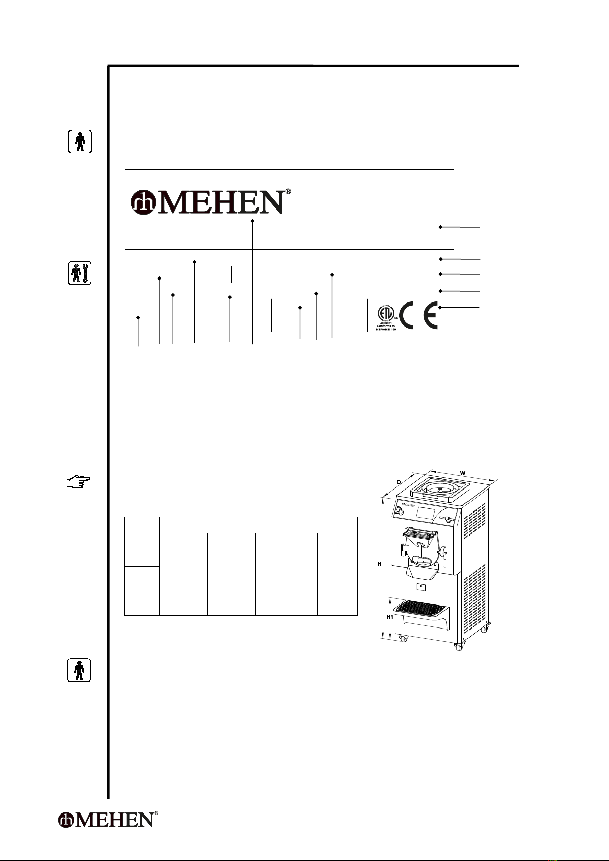
1.1 Nameplate of Machine
A nameplate consisting of manufacture's date is posted on the side panel of the
machine.
Xin Ling North Rd 1, ChunHua Street, Jiangning
District, Nanjing, 211122, P.R.CHINA
Tel: 0086-25-68552699
Http://www.mehen.com
Email:[email protected]
Model:
Cap.: Ltr
Gas: R404A Kg
Cooling:
~V. Ph. Hz. Amp.
N.W. Kg
P/N:
A B C D E F G H I
A=Net Weight B=Capacity C=Voltage D=Product Name E=Phase F=Brand
G=Product Number H=Frequency I=Gas & gas weight J=Certification
K=Electric Current L=Cooling method ( W-water, A-Air) M=Model
N=Manufacturer's contact information
1.2 Machine Lay-out
NOTE
Dimension may be various depending on
type of condensation.
1.3 Working Conditions
The following conditions are requested to ensure long term and steady operation:
Voltage Fluctuation: <10%
Ambient temperature: 0~35 ºC
Cooling water temperature: 5~30 ºC
Cooling water pressure: 1~8 bar
Max relative humidity: 85% ( without moisture condensation)
Model
Dimension (mm)
Width (W)
Depth (D)
Height (H)
H1
M10C
580
680
1320
410
M15C
M20C
680
980
1390
410
M30C
N
M
L
K
J
- 8 -
_________________________________________________________________________
CAUTION
The machine is not designed with anti-explosion standards. Thus make sure the
working place is out of explosive danger.
WARNING
MEHEN is NOT responsible for any accident happened to people or machine in
case the machine is used out of the designed condition.
_________________________________________________________________________
CHAPTER 2 INSTALLATION
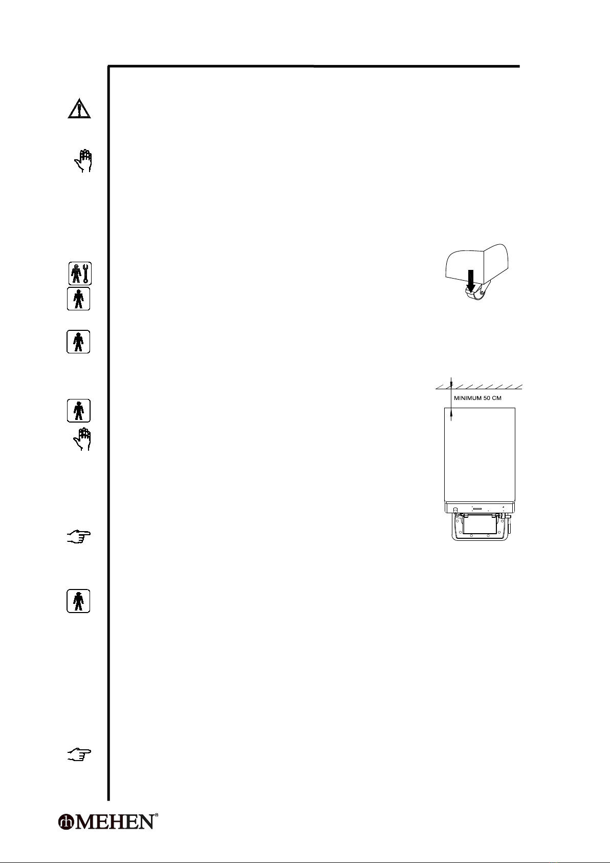
2.1 Position
After the machine is positioned, lock the caster immediately
to prevent movement of the machine during working.
2.2 Room Condition
The machine must be installed in room with a good air-ventilation so as to dispel
the hot air generated by the condenser. The room would be better with enough
space for operators to withdraw when necessary.
2.3 Installation of Air-cooled Machine
WARNING
Machine with air-cooled condenser must be installed no
less than 50 cm from the wall in order to allow free air
circulation around the condenser.
Clean the floor near and under the machine to avoid
paper and other stuffs entering into the condenser and
blocking a regular air flow.
TIPS
Insufficient air circulation affects both machine working and
its performance.
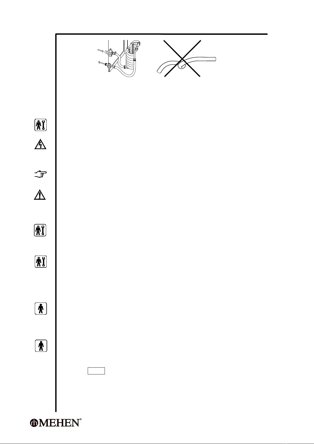
2.4 Installation of Water-cooled Machine
The inlet and outlet pipes of cooling water must be properly installed before
operation.
The requirements for the cooling water are:
Pure and no debris;
It's better to use soften water to prevent that furring appears inside of
the pipe to block the pipe and reduce the heat-exchange-efficiency.
Connect the cleaning water pipe to a drinkable water source if the machine is
equipped with a cleaning tap.
NOTE
MEHEN recommends to use steel pipe which can bear pressure up to 8 bar.
Keep the pipes fluent, don't bent.
- 9 -
TIPS
There is an electric water valve inside which can cut the water flow. Keep the
cooling water supply tap OPEN before starting the machine.
2.5 Electrical Connection
Before connecting the machine to the power mains, check power information
indicated on nameplate and choose a suitable power supply to the machine.
Get a circuit breaker protection device according to the parameters on nameplate
and install it to the power supply circuit during installation.
The specifications of the wires should strictly follow the requirements of the
machine and the minimum diameter is no less than 3 mm.
NOTE
Please refer to the label on the power wires.
WARNING
The PE For single phase and three phase, Yellow-green wire must be connected
to a good ground outlet.
2.6 Change Cable
If machine main cable is damaged, it must be replaced with same features and
carried out by an skilled technician.
2.7 Refrigerant Gas Refill
The freezing system has been filled with refrigerant gas and inspected by MEHEN
before delivery. If the machine met problem of gas leaking in use, a skilled
technician should be got to find the leakage, fix it then refill the refrigerant gas.
2.8 Machine Testing
Each machine from MEHEN is tested with full record before delivery. After the
machine is installed properly at the clients working site, it should be inspected
and tested by a skilled technician or engineer from MEHEN.
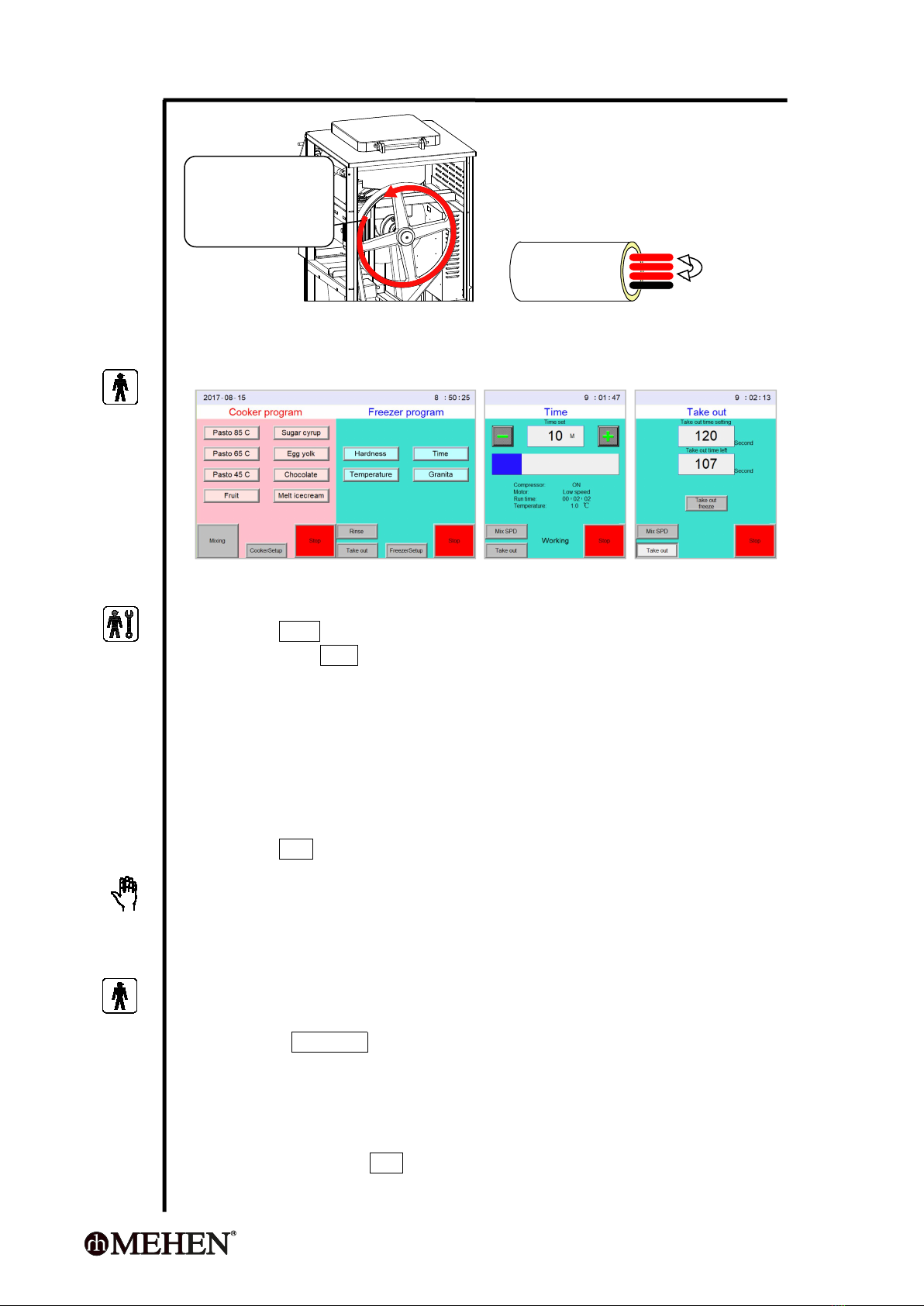
2.8.1 Check the Rotation Direction of Agitator (for three-phase machine only.)
Remove the side panel of the machine
Take out the blender from the cylinder, close and latch the cylinder door.
Test the rotation direction:
Push key RINSE to run it with empty freezing cylinder.
Check the rotate direction of the blending wheel according to above picture.
Otherwise, please exchange the connection of any two of three HOT-LINE to
change the rotating-direction, then test it again.
- 10 -
Assemble the machine panel after this test.
2.8.2 Running Test of Freezer
Prepare proper quantity (half of the named capacity) ice cream mix.
Well latch the cylinder door and outlet door then pull the mix into cylinder.
Press Rinse to mix the material for 30 seconds.
Then press Time to start freezing.
When the setting time finished, the compressor stop automatically, also the
buzzer will keep on beeping to remind the operator.
The operator can open the outlet door (part-47106) to take out the product.
If the operator want the product to come out slowly, use low speed.
If want it faster, use high speed.
When the cylinder is near to empty, please switch it to high speed to take
out it neatly.
Press Stop after take out all the product.
WARNING
Pure water can't be used to freeze in the cylinder under any condition,
otherwise may cause the blender seriously damaged.
2.8.3 Running Test of Cooker
Prepare proper quantity (half of the named freezer capacity) of water, make
sure the valve is closed, pull into the cooker tank then close the cover.
Press Pasto 85 C to start cooking.
Inspect the blending and display, the temperature shall increase as time
being.
When the setting temperature achieved, the cooking stop and the blending
continues.
Push key left-side Stop to stop blending.
exchange wires
to change direction
Correct rotation
direction of
agitator
- 11 -
Open the valve to take out the hot water.
WARNING
Never start cooking when the mix tank is empty.
CHAPTER 3 EXPLOSIVE DIAGRAM
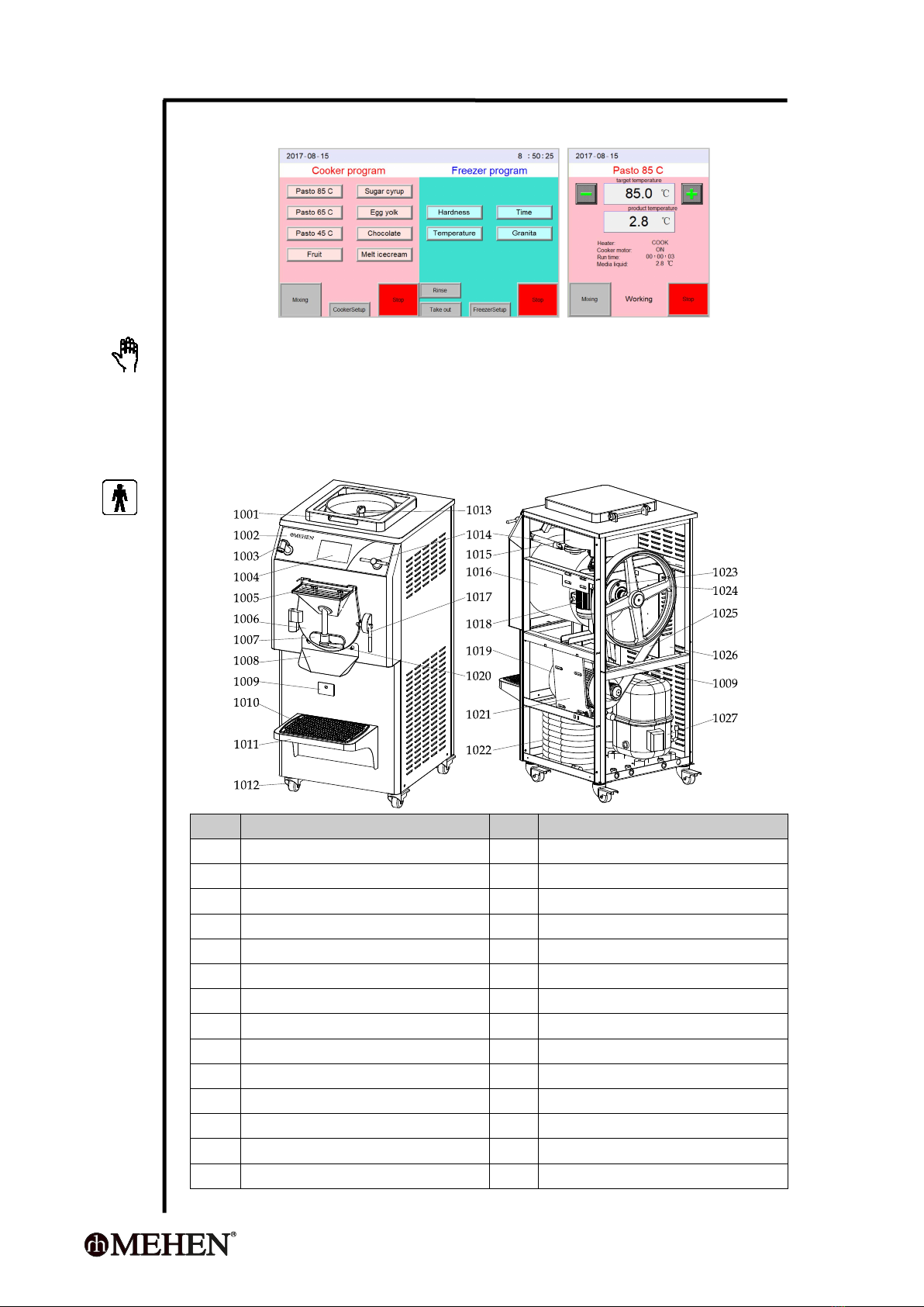
3.1 Components Position
Pos.
Description
Pos.
Description
1001
Cooker cover
1002
Plastic panel
1003
Rinse spigot
1004
Touch screen controller
1005
Inlet cover
1006
Cylinder door
1007
Outlet door
1008
Output groove
1009
Waste liquid collector
1010
Anti slip pad
1011
Pan holder
1012
Caster
1013
Cooker blender
1014
Valve handle
1015
Cooking tank
1016
Freezing cylinder
1017
Door latch//Valve wrench
1018
Agitating motor, freezer
1019
Agitating motor holder, freezer
1020
Output wrench
1021
Freezer motor shelf
1022
Condenser
1023
Agitating motor, cooker
1024
Driving pulley
1025
Belt
1026
Electrical components box
1027
Compressor

- 12 -
3.2 Freezer Driving Parts Diagram
47001
47002
47003
47004
47005
47006
47008
47007
47009
47010
Pos.
Description
Pos.
Description
47001
Bearing holder
47002
Shaft
47003
Bearing
47004
Bearing sleeve (small)
47005
Bearing sleeve (big)
47006
Bearing stop small nut
47007
Key
47008
Bearing stop big nut
47009
Drive pulley
47010
Pulley locking screw (3 pieces)
3.3 Freezer Blender Diagram
4801
4802
4803 4805
4804
Pos.
Description
Pos.
Description
4801
Radial support
4804
Plastic blade
4802
Blender frame
4805
Cylinder bottom seal
4803
Axis support
Pull to take out
- 13 -
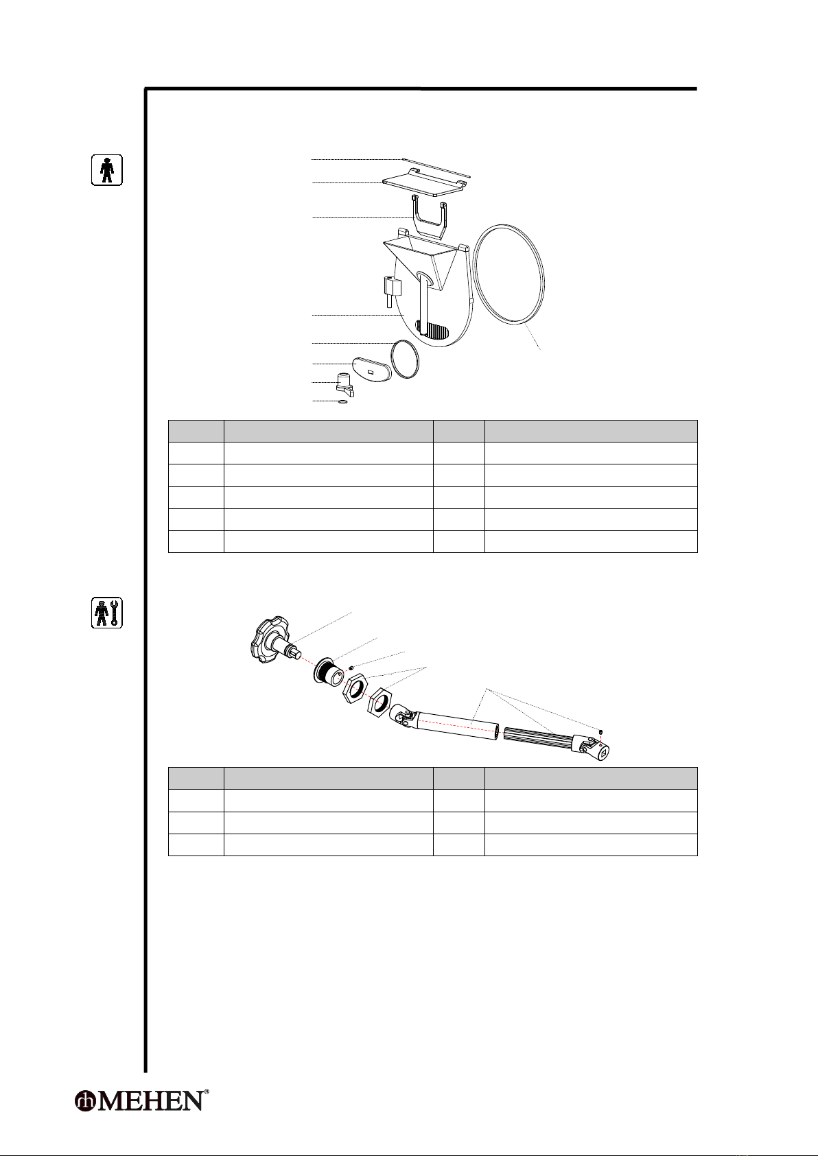
3.4 Freezing Cylinder Door Diagram
47101
47102
47103
47104
47105
47106
47107
47108
47109
Pos.
Description
Pos.
Description
47101
Cover axis
47106
Outlet door
47102
Inlet cover
47107
Handle
47103
Inlet stopper
47108
Handle stop ring
47104
Cylinder door
47109
Cylinder seal ring
47105
Outlet door seal ring
3.5 Valve Driving Parts Diagram
37001
37002
37003
37004
37005
Pos.
Description
Pos.
Description
37001
Valve wrench
37002
Holder
37003
Nuts
37004
Holding nuts
37005
Drive set

- 14 -
3.6 Cooker Blender Parts Diagram
37110
37111
37112
37113
37114
37105
37107
37108
39109
37106
37101
37102
37103
37104
37115
37101
37103
Pos.
Description
Pos.
Description
37101
Mixing blades
37102
Mixing frame
37103
Bottom blades
37104
Bearing
37105
Driving shaft
37106
Key
37107
Seal O-ring
37108
Waterproof bearing sleeve
37109
Seal O-ring
37110
Driving shaft holder
37111
Seal O-ring
37112
Motor support
37113
F connector
37114
Reduction gear
37115
Motor
CHAPTER 4 CONTROLS AND OPERATION
4.1 Freezer Cylinder Door Operation
1
2
1
2
1
2
- 15 -
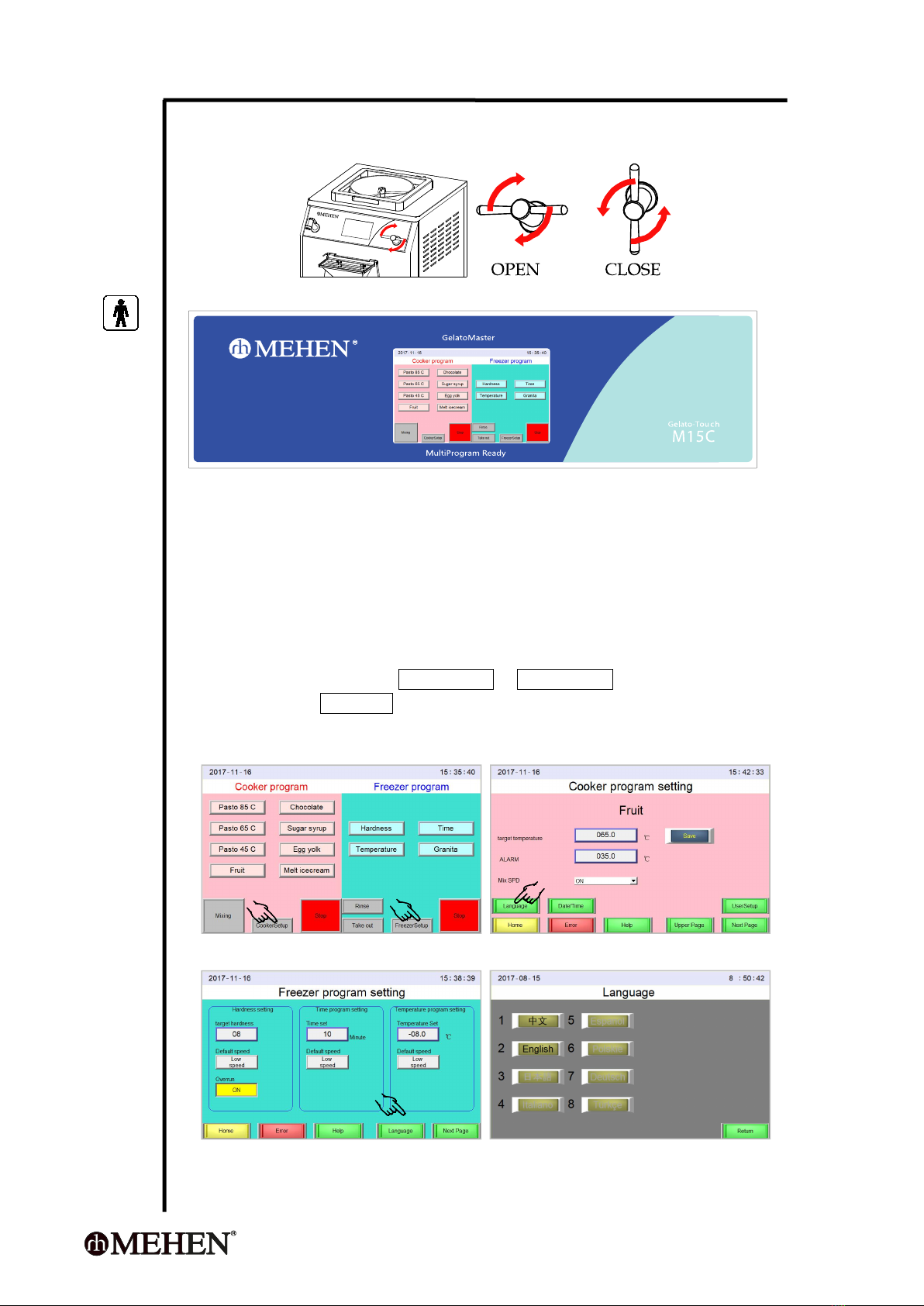
4.2 Transfer the Hot Mix From Boiler to Freezer Cylinder
Turn the valve handle (part 1014) can open or close the valve.
4.3 Electric Control Panel
4.4 Common Operations
This machine has two independent parts, A boiler for pasteurization on the top
and another batch freezer below. They are connected together by pipe and an
valve. There is one controller, left side pasteurization and right side for freezer.
They can work at same time or independently. There are some common
operations here below:
4.4.1 Language Setting
This controller offers a quick language setting.
On Home-page, press CookerSetup or FreezerSetup and program setting;
Then press Language to enter Language-setting;
Press the Language you want.
English to other language
step 1 step 2
step 2 step 3
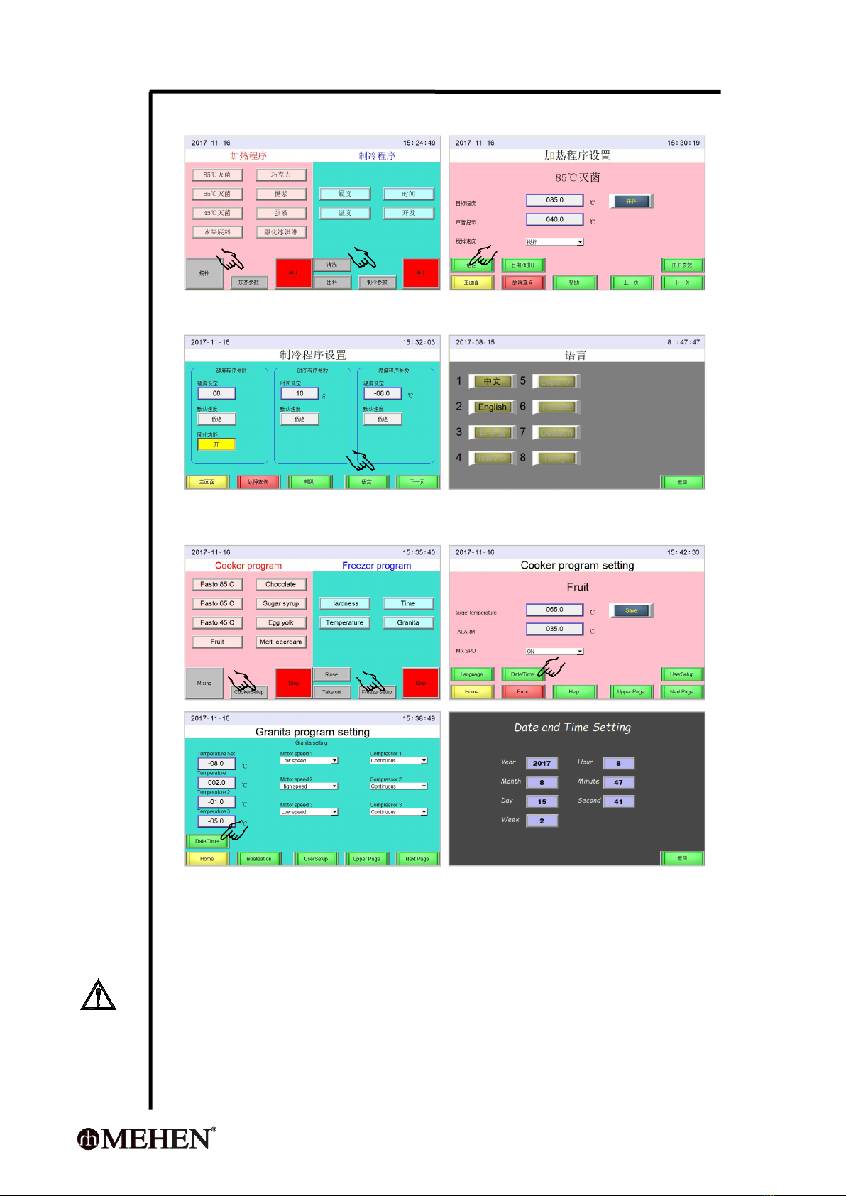
- 16 -
Chinese to other language
step 1 step 2
step 2 step 3
4.4.2 Date and Time setting
4.4.3 Controller Initialization
This initialization will reset all the parameters to factory setting.
This operation need to input the user security code 1111.
CAUTIOIN
The parameters are important to ensure the correct performance of the machine.
The initialization can be operated by a qualified technician only.
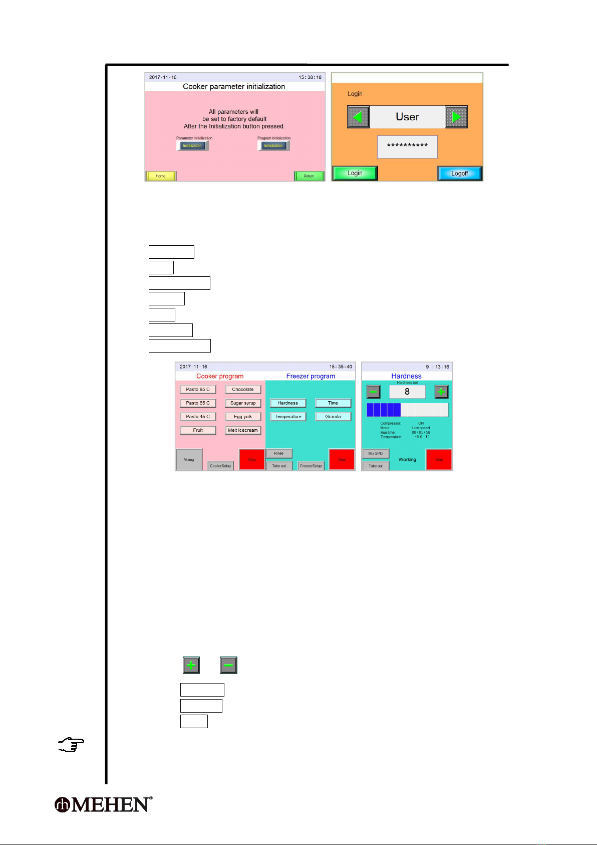
- 17 -
4.5 Freezer Operation
4.5.1 Freezer Daily Operation
It will enter home-page after power on and if there is no problems.
Press Hardness to start a product making with hardness-control-mode;
Press Time to start a product making with timer-control mode;
Press Temperature to start a product making with temperature-control-mode;
Press Granita to start a product making with developer-control-mode;
Press Rinse to perform a Rinse for cleaning;
Press Take Out to run a product taking out operation;
Press FreezerSetup to regulate the parameters.
4.5.2 Freezer Producing Programs
There are 4 programs for producing, you can use them according to your recipe or
habit accordingly.
4.5.2.1 Hardness Mode
Under this mode, the controller will:
Detect the product texture hardness, it will finish freezing and turn to
agitating only when the setting hardness achieved;
Detect the product temperature and change the agitating speed according
to setting.
During processing, the operator can:
Press or to increase or decrease the target hardness;
Press Take Out to finish the processing and turn to take out the product;
Press Mix SPD to switch the agitating speed;
Press STOP to stop the processing and turn to Standby mode.
Tips
The controller will automatically record the new setting and repeat from next time.
- 18 -
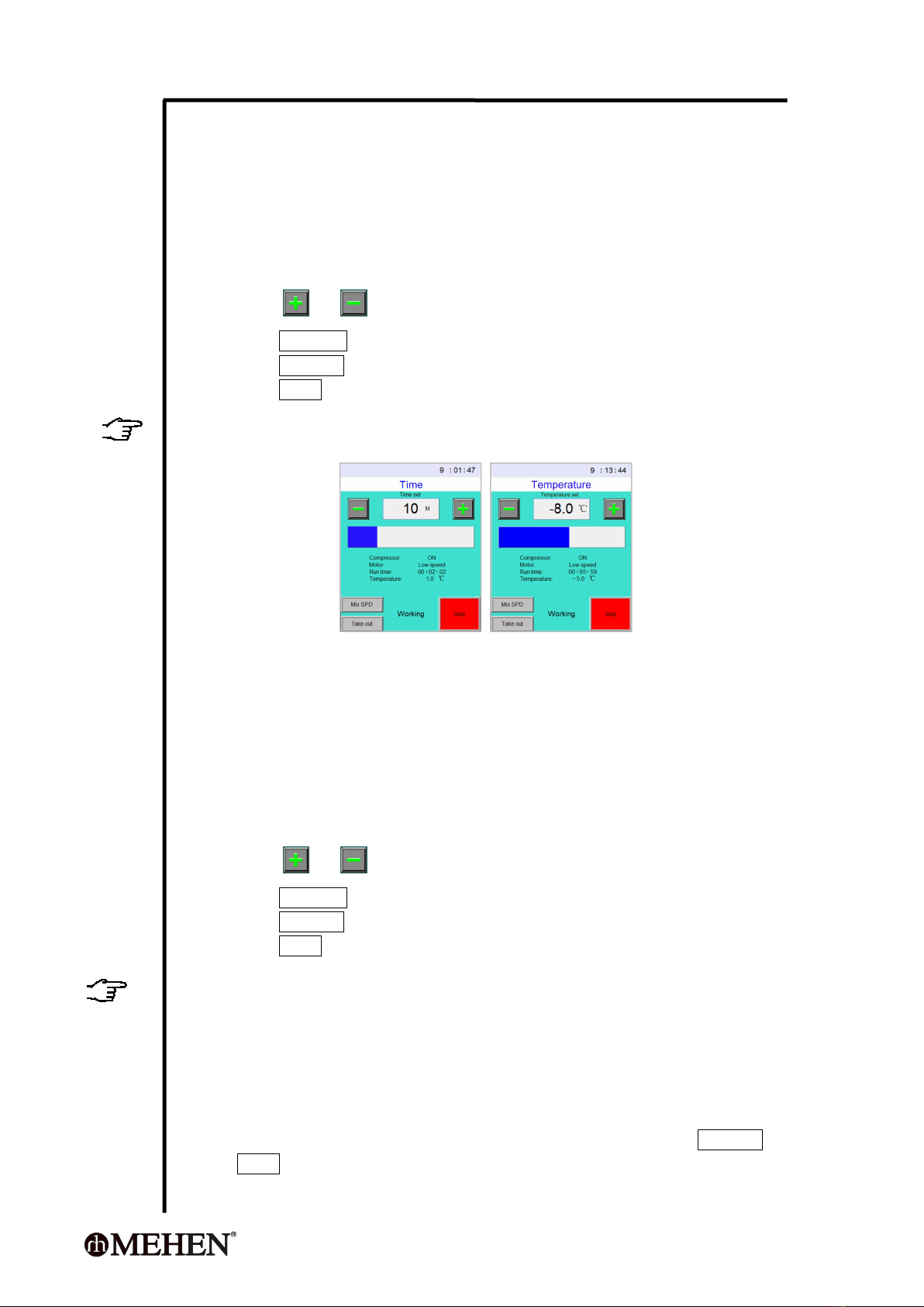
4.5.2.2 Time Mode
Under this mode, the controller will:
Perform a freezing processing according to the Time setting, it will finish
the freezing and turn to agitating only when the setting time is over;
Detects and display the product temperature.
During processing, the operator can:
Press or to increase or decrease the time setting;
Press Take Out to finish the processing and turn to take out the product;
Press Mix SPD to switch the agitating speed;
Press STOP to stop the processing and turn to Standby mode.
Tips
The controller will record the new setting and repeat from next time.
4.5.2.3 Temperature Mode
Under this mode, the controller will:
Perform a freezing processing according to the Temperature setting, it will
stop freezing and turn to agitating when the setting temperature is
achieved;
The compressor will restart if the product temperature increase 2 °C;
Detects and display the product temperature.
During processing, the operator can:
Press or to decrease or increase the temperature setting;
Press Take Out to finish the processing and turn to take out the product;
Press Mix SPD to change the agitating speed;
Press STOP to stop the processing and turn to Standby mode.
Tips
The controller will automatically record the new setting and repeat for next times.
Only Temperature-Mode has temperature holding function.
4.5.2.4 Granita Mode
This mode offers a flexible option for the chef to produce different
products;
The freezing will finish if the Setting Temperature is achieved;
The agitating will continuous until the operator manually press Take out or
STOP;
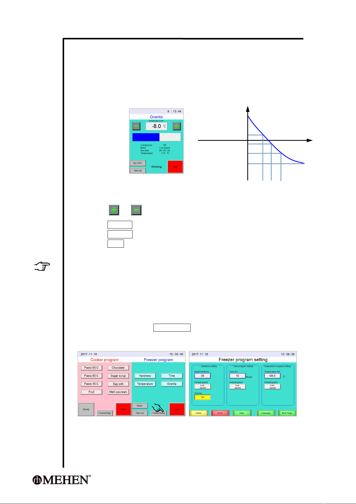
- 19 -
The entire temperature range is divided into 4 segments ( Fig 1.);
In each temperature range:
The operator can program the compressor: Continuous or Intermittent
working;
The operator can program the agitating motor: Low Speed,
Intermittent Low Speed, High Speed or Intermittent High Speed.
S1 S2 S3 S4
Fig 1
During processing, the operator can:
Press or to decrease or increase the temperature setting;
Press Take out to finish the processing and turn to take out the product;
Press Mix SPD or switch the agitating speed;
Press STOP to stop the processing and turn to Standby mode.
TIPS
The controller will automatically record the new Target Temperature Setting and
repeat from next time. We suggest you use this program only if you are
experienced.
4.5.3 Freezer Program Setting
4.5.3.1 How to Set Freezer Program?
On Home-page, press FreezerSetup will enter program setting mode;
Press the volume frame to regulate.
The new setting will be saved automatically.
time
temperature
Temperature 1
Temperature 2
Temperature 3
Target temperature
- 20 -
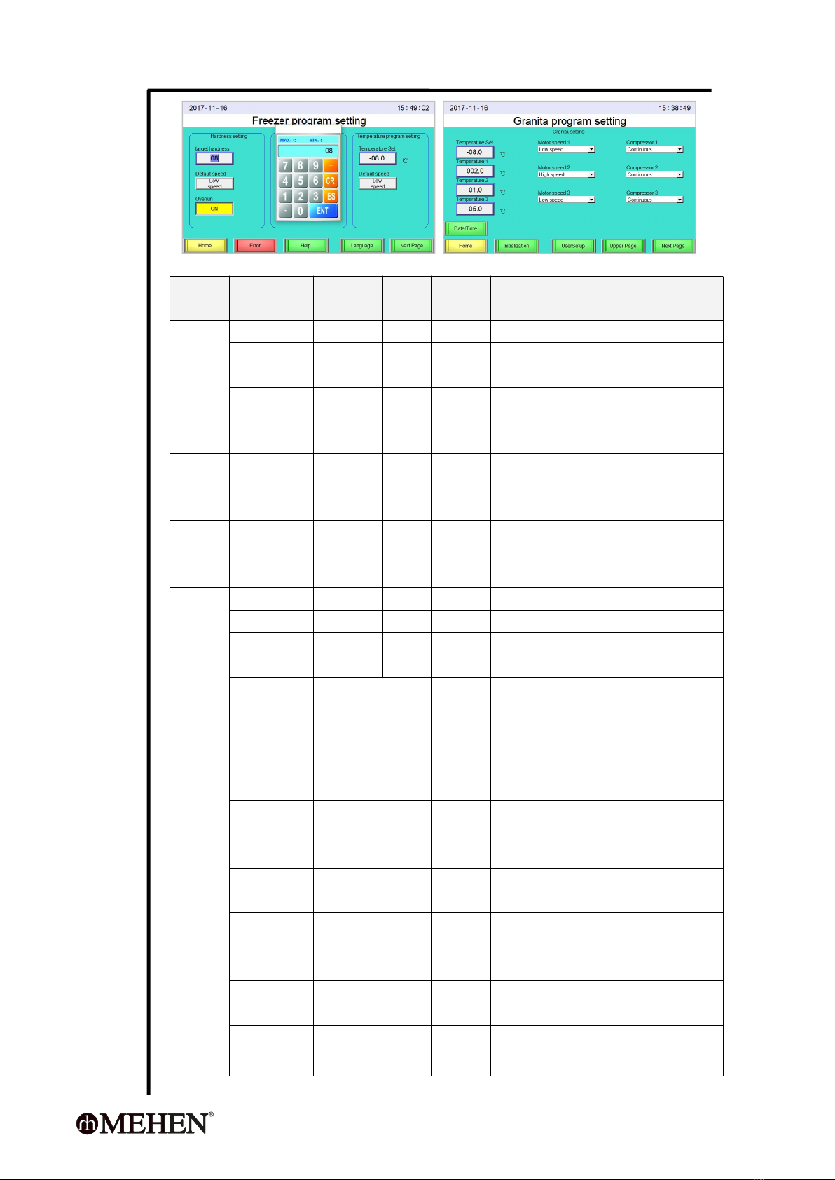
4.5.3.2 Freezer Programs Setting
Program
Parameters
Range
Unit
Factory
Volume
Explanation
Hardness
Target hardness
1~12
==
8
Higher volume results in harder product.
Default speed
Low/High
==
Low
Low: Low-speed agitation.
High: High-speed agitation.
Overrun
On/Off
==
On
The machine will automatically switch to
high-speed when the product temperature
is in the range of 1 °C ~ -3 °C.
Time
Time setting
2~35
minutes
10
Freezing time.
Default
speed
Low/High
==
Low
Low: Low-speed agitation.
High: High-speed agitation.
Temperature
Target temperature
-15 ~ 2
°C
-8
Target temperature.
Default
speed
Low/High
==
Low
Low: Low-speed agitation.
High: High-speed agitation.
Granita
Target temperature
-15 ~ 2
°C
-8
Target temperature.
Temperature1
-15 ~ 80
°C
2.0
Minimum temperature of S1 (refer to Fig 1)
Temperature2
-15 ~ 80
°C
-1.0
Minimum temperature of S2 (refer to Fig 1)
Temperature3
-15 ~ 80
°C
-5.0
Minimum temperature of S3 (refer to Fig 1)
Motor speed 1
Low speed
Intermittent low
High speed
Intermittent high
Low speed
Agitation speed in temperature range S1
(refer to Fig 1)
Compressor 1
Continuous
Intermittent
Continuous
Compressor mode in temperature range S1
(refer to Fig 1)
Motor speed 2
Low speed
Intermittent low
High speed
Intermittent high
High
speed
Agitation speed in temperature range S2
(refer to Fig 1)
Compressor 2
Continuous
Intermittent
Continuous
Compressor mode in temperature range S2
(refer to Fig 1)
Motor speed 3
Low speed
Intermittent low
High speed
Intermittent high
Low speed
Agitation speed in temperature range S3
(refer to Fig 1)
Compressor 3
Continuous
Intermittent
Continuous
Compressor mode in temperature range S3
(refer to Fig 1)
Motor speed 4
Low speed
Intermittent low
High speed
Low speed
Agitation speed in temperature range S4
(refer to Fig 1)
This manual suits for next models
3
Table of contents
Other MEHEN Commercial Food Equipment manuals

Popular Commercial Food Equipment manuals by other brands


Rational
Rational MI 2076 Modification Instructions

Vollrath
Vollrath Bain Marie Two Pan Operator's manual

Henny Penny
Henny Penny LOV3 quick reference

ZANOLLI
ZANOLLI SYNTHESIS 08/50 V PW GAS Manual for installation

Rühle
Rühle GR 50 Translation of the original instructions

NORPOLE
NORPOLE NP1R-PT user manual