Meiji GFCI User manual

Installing and testing GFCI Receptacle
Please read this leaflet completely before getting started
1. What is a GFCI?
A GFCI receptacle is different from
conventional receptacle. In the event of
a ground fault, a GFCI will trip and
quickly stop the flow of electricity to
prevent serious injury.
Definition of Ground fault:
Instead of following its normal safe
path, electricity passes through a
person’s body to reach the ground. For
example a defective appliance can cause
a ground fault.
A GFCI receptacle does not protect
against circuit overloads, short circuits,
or shocks. For example, you can still be
shocked if you touch bare wires while
standing on a non-conducting surface,
such as a wood floor.
2. The GFCI’s features:
3. Should you install it?
Installing GFCI receptacle can be more complicated than installing a conventional
receptacle
Make sure you:
Understand basic wiring principles and techniques.
Can interpret wiring diagram.
Have circuit wiring experience.
Are prepared to take a few minutes to test your work, making sure that you
have wired the GFCI receptacle correctly.
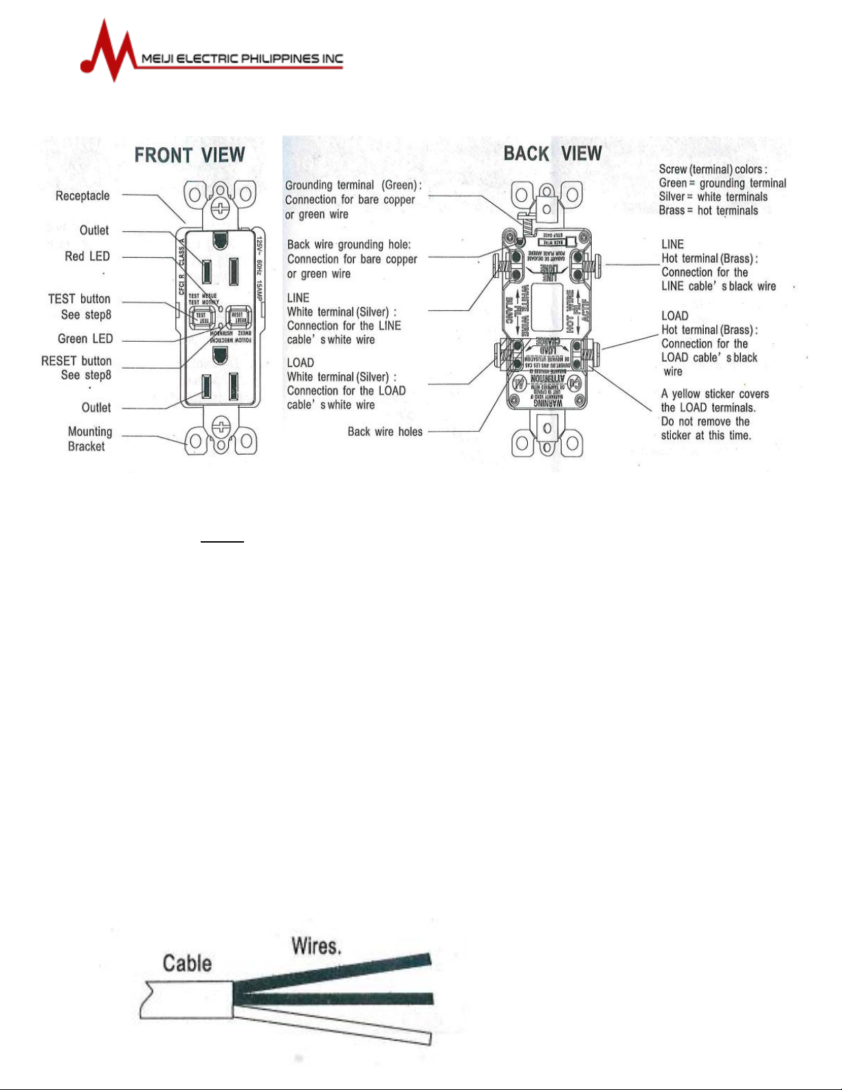
4. LINE vs LOAD
A cable consists of 2 or 3 wires.

LINE cable:
Delivers power from the service panel (breaker panel or fuse box) to the GFCI, If
there is only one cable entering the electrical box, it is the LINE cable. This cable
should be connected to the GFCI‘s LINE terminals only.
LOAD cable:
Delivers power from the GFCI to another receptacle in the circuit. This cable
should be connected to the GFCI’s LOAD terminals only. The LOAD terminals are
under the yellow sticker. Do not remove the sticker at this time.
5. Turn the power OFF
Plug an electrical device, such as a lamp or a radio, into the receptacle on which
you are working. Turn the lamp or radio on. Then go to the service panel. Find the
breaker or fuse that protects that receptacle. Place the breaker in off positon or
completely remove the fuse. The lamp or radio should turn off.
Next, plug in and turn ON the lamp or radio at the receptacles other outlet to
make sure the power is OFF at both outlets. If the power is not OFF, stop work
and call an electrician to complete the installation.
6. Identifying Cable/Wires
Important:
Do not install the GFCI receptacle in an electrical box containing (a) more than 4
wires. (Not including the grounding wires) or (b) cable with more than two wires
(not including the grounding wire). Contact the qualified if either (a) or (b) is true.
If you are replacing an old receptacle, pull it out of the electrical box without
disconnecting the wires.
If you see one cable (2-3 wires), it is the LINE cable. The receptacle is probably in
position C (see diagram below). Remove the receptacle and go to step 7A.
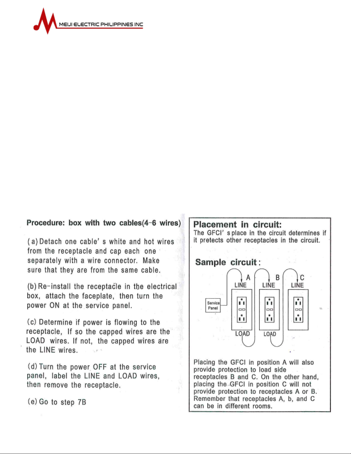
If you see two cables (4-6 wires), the receptacle is probably in position A or B (see
diagram below). Follow step a –e of the procedure below.

A: One cable (2 or 3 wires) entering the box
Connect the LINE cable to the LINE terminals:
The white wire connects to the White terminal (Silver)
The black wire connects to the Hot terminal (Brass)
Connect the grounding wire (only if there is a grounding wire):
For a box with no grounding terminal: (diagram not shown) Connect the LINE
cable’s bare copper (to green)wire directly to the grounding terminal of the
GFCI receptacle
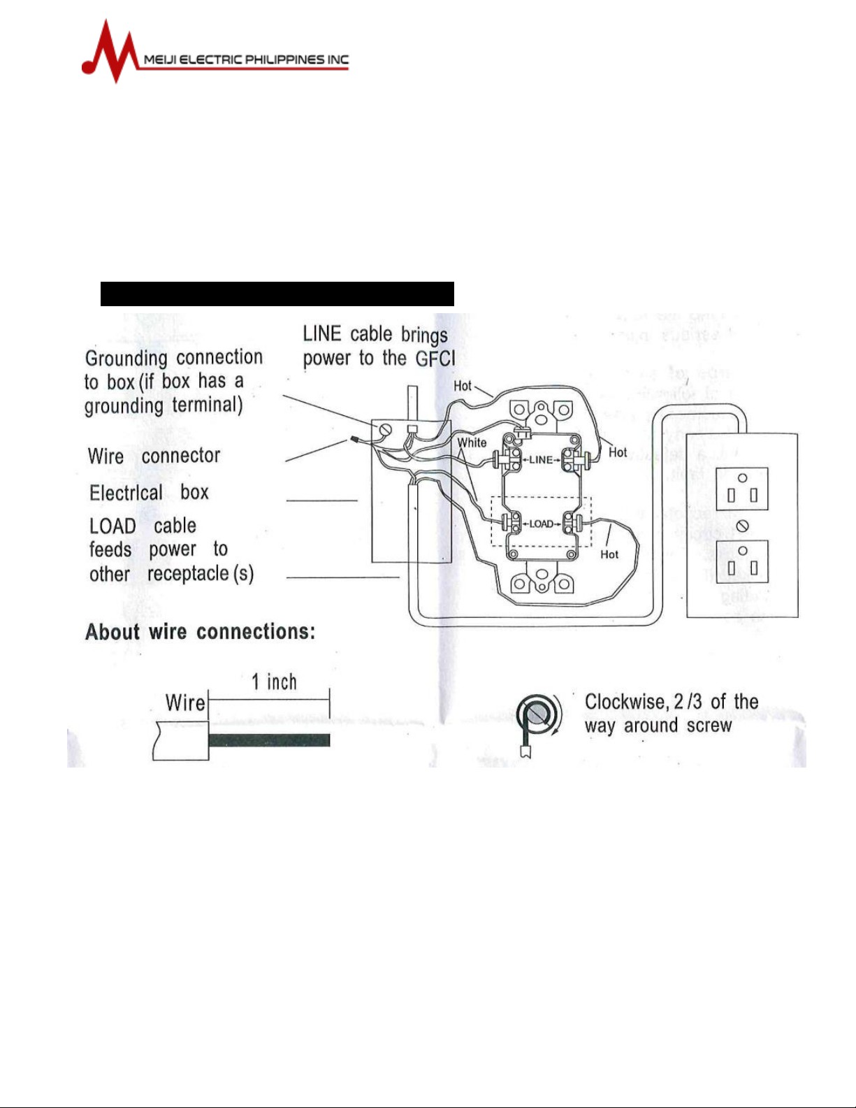
For a box with grounding terminal (diagram shown above) Connect a 6-inch
bare copper (or green) 12 to 14 AWG wire to the grounding terminal on the
GFCI. Connect similar wire to the grounding terminal on the box. Connect the
ends of these wires to the LINE cable’s bare copper (or green) wire using a wire
connector. If these wire are already in place, check the connection
Connect the wires (choose A or B) … only after reading previous part completely
Complete the installation:
Fold the wires into the box, keeping the grounding wire away from the white
and hot terminals. Screw the receptacle to the box and attached the faceplate.
Go to step 8.
B: Two cable (4 or 6 wires) entering the box
Connect the LINE cable to the LINE terminals:
The white wire connects to the White terminal (Silver)
The black wire connects to the Hot terminal (Brass)
Connect the LOAD cable wires to LOAD Terminal:
Remove the yellow sticker to reveal the load terminals
The white wire connect to the White terminal (Silver)
The black wire connect to the Hot terminal (Brass)

Connect the grounding wires as shown above (only if there is a grounding wire):
Connect a 6-inch bare copper (or green) 12 or 14 AWG wire to the grounding
terminal on the GFCI if the box has a grounding terminal, also connect a similar
wire to the grounding terminal box. Connect the ends of these wires to the
LINE and LOAD cable’s bare copper (or green) wire using a wire connector. If
these wires are already in place, check the connection.
Complete the installation:
Fold the wires into the box, keeping the grounding wire away from the White
and Hot terminals. Screw the receptacle to the box and attach the face plate.
Go to step 8.
8. TEST your work
Why perform this test?
If you miss wire the GFCI it may not prevent personal injury or death due to a
ground fault (electric shock)
If you mistakenly connect the LINE wire to the LOAD Terminal, the GFCI will
still operate like an ordinary receptacle, but it will not interrupt ground fault.

Procedure:
a) Turn the power ON at the service panel. Press RESET button
fully. Plug the lamp or radio into the GFCI (and leave it plugged-
in) to verify that the power is ON. If there is no power, go to
Troubleshooting.
b) Press the blue TEST button in order to trip the device. This
should stop the flow of electricity, making the lamp or radio shut
OFF. Note that the red RESET button will pop-out. If the power
stays ON, go to Troubleshooting. If the power goes OFF, you
have installed the GFCI receptacle correctly. To restore the
power, press the RESET button.
c) If you installed your GFCI using step 7B plug a lamp or radio into
surrounding receptacle to see which one(s), in addition to GFCI,
lost power when you press the TEST button. Do not plus a life
saving device to any receptacle that lost power. Place a “GFCI
Protected” sticker on every receptacle that lost power.
d) Press the TEST button (then RESET button) every month to
assure proper operation
e) If the GFCI control circuitry is in the form of short circuit or
tripping coil is burnt out. The red light indicator will turn on; this
means that the GFCI receptacle reached its end of life.
TROUBLESHOOTING
Turn the power OFF and check the wire connections against the appropriate wiring diagram in step 7A or 7B.
Make sure that there are no loose wires or loose connections. Also, it is possible that you reversed the LINE
and LOAD connection. LINE/LOAD reversal will be indicated by power remaining ON at the GFCI after you
press the GFCI’s TEST button. Reverse the LINE and LOAD connection if necessary. Start the test from the
beginning of step 8 if you rewired any connections to the GFCI.

GENERAL INFORMATION
GFCI receptacle rating:
15A –125V AC Duplex Receptacle
20A –125V AC Duplex Receptacle
20A –125V AC Blank Face
All devices rated 20A feed-through
IF GFCI RECEPTACLE does not function as in 1 below,
Notify a qualified electrician that you have lost protection.
TEST INFORMATION
TO TEST:
1. Push the TEST button. The RESET button should pop out. Power should now be
off at this receptacle and all receptacles down the line. TEST then ALL with lamp.
2. WARNING: IF THE RESET BUTTON DOES NOT POP OUT AND THE LAMP REMAINS
LIGHTED, GROUND FAULT PROTECTION IS NOT PROVIDED. DO NOT USE THE
RECEPTACLE. RE-CHECK TO MAKE SURE YOUR INSTALATION IS DONE CORRECTLY.
3. To restore power, push, and then release the RESET button.
This ground fault circuit interrupter receptacle is designed to protect people from the
hazard of line ground electric shock. This protection is afforded to people using tools or
appliances operating from the receptacle. If protection is fed to the rest of the circuit, those
receptacles are also protected if properly installed. It does not prevent electrical shock, but
limits the shock time to a period deemed safe for normally healthy persons.
It does not protect a person who comes to contact with both power lines.
Ground fault circuit interrupter receptacle does not protect against overload; this must be
done at the fuse box by fuses or beakers
If an appliance continuously trips the GFCI Receptacle, the appliance is defective and should
be repaired or replaced.
Table of contents


