Mitsubishi Electric AE630-SW User manual

MITSUBISHILow-VoltageAirCircuitBreakerstypeAE
CC-Link Interface unit (BIF-CC)
INSTRUCTION MANUAL
ACB types covered in this manual
AE630-SW AE1000-SW AE1250-SW AE1600-SW
AE2000-SWA
AE2000-SW AE2500-SW AE3200-SW
AE4000-SWA
AE4000-SW AE5000-SW AE6300-SW
IMPORTANT NOTE: Before using these Series AE breakers, please read these
instructions carefully, and make sure that all actual users also read them.

E-2
●SAFETY PRECAUTIONS ●
Make sure to observe the following matters of safety
Before using the device, make sure to read these safety precautions and instruction manual thoroughly. The cautionary items
noted herein are of the utmost importance for the safe use of this device, and should always be strictly followed.
Make sure that the final user receives this manual.
This instruction manual is prepared for an electrical expert.
The following symbols have been used:
DANGER
DANGER
Do not use the device on the conditions over range. Failure to do so may result in fire.
Do not touch the terminals. There is a risk of electrical shock.
CAUTION
Failure to follow these instructions
may result in dangerous conditions,
which in turn could lead to severe
personal injury or even death.
Failure to follow these instructions
may result in dangerous conditions,
which could result in moderate to
slight personal injury or damage to
equipment and facilities
This means prohibition. Never ignore
this indication.
Make sure to follow these
instructions without fail.
CAUTION
A qualified electrician should install this equipment.
Make sure to tighten the terminal screws to the torque specified in this manual. Failure to do so may result in malfunction
or fire.
Do not install in areas subject to high temperatures, high humidity, dust, corrosive gas, vibrations, shocks, etc. To do so
may result in malfunction or fire.
Install so that trash, concrete dust, iron filings or rainwater cannot get into the device interior. Failure to do so may result
in malfunction or fire.

E-3
■EMC Directive
In IEC60947-2, following EMC tests are required.
1) Radiated radio frequency emission
2) Radiated radio frequency electromagnetic field immunity
BIF-CC is confirmed to IEC60947-2 in accordance with following conditions.
1) BIF-CC shall be installed in the panel board. It effects not only for safe against electric shock but also to interrupt
noise emission from the device.
2) When attaching the panel's top plate or base plate, mask painting and weld so that good surface contact can be
made between the panel and plate.
3) To ensure good electrical contact with the panel board, mask the paint on the installation bolts of the inner plate
in the panel board so that contact between surfaces can be ensured over the widest possible area.
4) Earth the panel board with a thick wire so that a low impedance connection to ground can be ensured even at high
frequencies (*ground resistance: 100 ohm or less).
5) Provide an earthing point near the BIF-CC. Earth the FG terminal of BIF-CC with the thickest and shortest wire
possible (*ground resistance: 100 ohm or less). The FG terminal function is to pass the noise generated in the
BIF-CC or the noise from outside to the ground, so an impedance that is as low as possible must be ensured.
Also, in case that the CC-Link cable is extracted to the outside of the panel board, earth it at point close to the
exit of panel board. An appropriate installation has the effect of suppressing the generation of the
electromagnetic induction and the high frequency noise.
6) If the measure described above does not provide sufficient shielding effects, fit ferrite cores to the power supply
line of BIF-CC. We recommend ferrite core made by TDK (type: ZCAT2032-0930). For CC-Link cables, however,
do not use ferrite cores.
7) CC-Link cable, Internal transmission cable and BIF-CON cable shall be kept distance more than 100mm from the
power distribution circuit. However, when parallel installation with the power distribution circuit is required, it is
necessary to increase to 300mm.
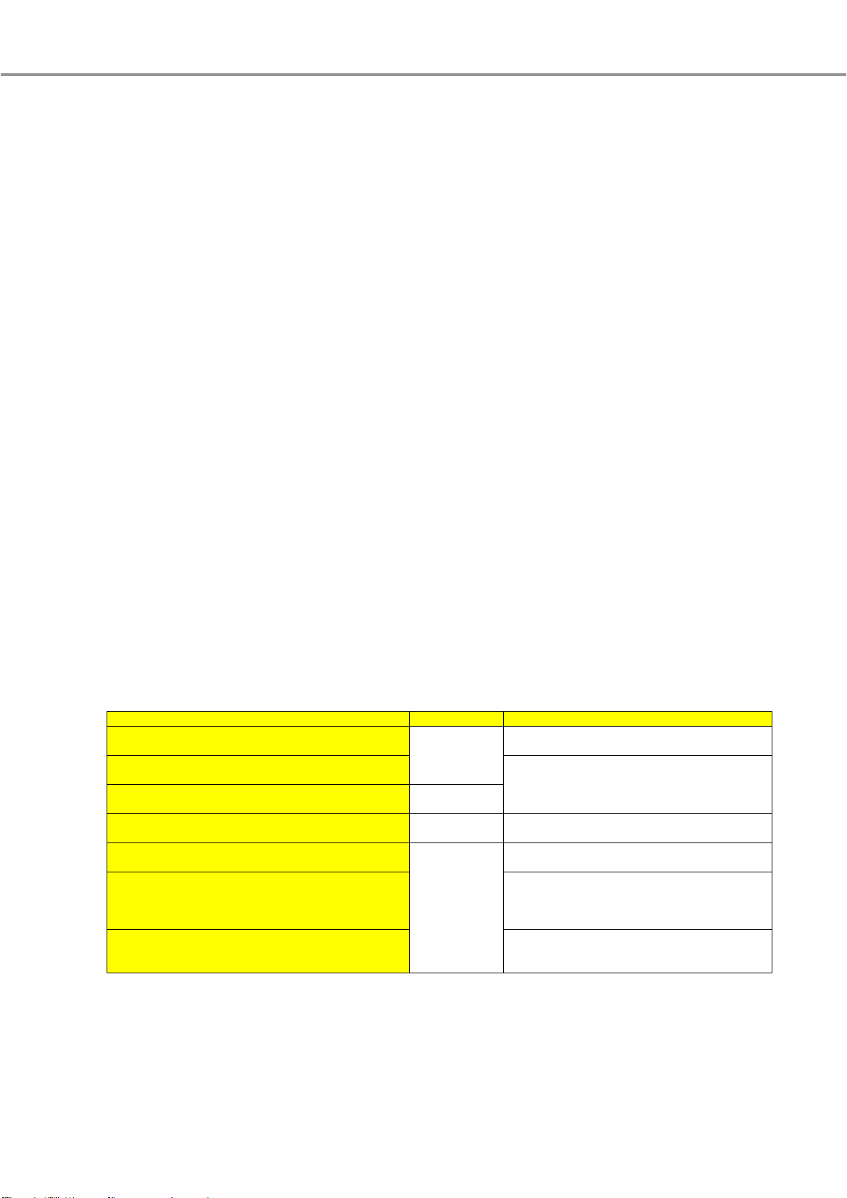
■Dielectric voltage test
The dielectric voltage test should be executed according to the table below. Do not test in points other than a
following table because unit is damaged.
Measuring point
Condition
Notes
Between main circuit
and BIF-CC terminals (P1 and P2)
2500VAC 1min.
Between main circuit
and BIF-CC terminals (DA, DB, DG, SLD and FG)
1. Connect terminals (DA, DB, DG, SLD and FG)
to the earth side.
2. Apply voltage across the entire terminals
(DA, DB, DG, SLD and FG).
Between BIF-CC terminals (P1 and P2)
and BIF-CC terminals (DA, DB, DG, SLD and FG)
1500VAC 1min.
Between main circuit
and BIF-CON terminals (C1, C2, A1, A2, U1 and U2)
2500VAC 1min.
Between BIF-CC terminals (P1 and P2)
and BIF-CON terminals (C1, C2, A1, A2, U1 and U2)
1500VAC 1min.
Between BIF-CC terminals (DA, DB, DG, SLD and FG)
and BIF-CON terminals (C1, C2, A1, A2, U1 and U2)
1. Connect terminals (DA, DB, DG, SLD and FG)
to the earth side.
2. Apply voltage across the entire terminals
(DA, DB, DG, SLD and FG).
BIF-CON terminals (C1 and C2),
BIF-CON terminals (A1 and A2),
BIF-CON terminals (U1 and U2), each other
■Guarantee
The period of guarantee is for 1 year from the sale date except in case of the failure has been caused by bad handling
of the device.

E-4
- Table of Contents -
1. System Overview ・・・・・・・・・・・・・・・・・・・・・・・・・・・・・・・・・・・・・・・・・・・・・・・・・・・・・・・・・・・・・・・・・・・・・・・・・・・・・・・・・ 5
2. Specifications
2.1 BIF-CC ・・・・・・・・・・・・・・・・・・・・・・・・・・・・・・・・・・・・・・・・・・・・・・・・・・・・・・・・・・・・・・・・・・・・・・・・・・・・・・・・・・・・・・・ 6
2.2 BIF-CON (Option) ・・・・・・・・・・・・・・・・・・・・・・・・・・・・・・・・・・・・・・・・・・・・・・・・・・・・・・・・・・・・・・・・・・・・・・・・・・・・・ 7
3. Part Names and Settings
3.1 BIF-CC ・・・・・・・・・・・・・・・・・・・・・・・・・・・・・・・・・・・・・・・・・・・・・・・・・・・・・・・・・・・・・・・・・・・・・・・・・・・・・・・・・・・・・・・ 8
3.2 BIF-CON (Option) ・・・・・・・・・・・・・・・・・・・・・・・・・・・・・・・・・・・・・・・・・・・・・・・・・・・・・・・・・・・・・・・・・・・・・・・・・・・・・ 12
4. Installation
4.1 IEC rail installation ・・・・・・・・・・・・・・・・・・・・・・・・・・・・・・・・・・・・・・・・・・・・・・・・・・・・・・・・・・・・・・・・・・・・・・・・・・・・・ 16
4.2 Bracket installation ・・・・・・・・・・・・・・・・・・・・・・・・・・・・・・・・・・・・・・・・・・・・・・・・・・・・・・・・・・・・・・・・・・・・・・・・・・・・ 17
5. Communication items
5.1 Communication items ・・・・・・・・・・・・・・・・・・・・・・・・・・・・・・・・・・・・・・・・・・・・・・・・・・・・・・・・・・・・・・・・・・・・・・・・・・ 18
5.2 Measurement items (detail) ・・・・・・・・・・・・・・・・・・・・・・・・・・・・・・・・・・・・・・・・・・・・・・・・・・・・・・・・・・・・・・・・・・・・・ 21
5.3 Setting items (detail) ・・・・・・・・・・・・・・・・・・・・・・・・・・・・・・・・・・・・・・・・・・・・・・・・・・・・・・・・・・・・・・・・・・・・・・・・・・・ 21
6. Troubleshooting
6.1 Errors detected by BIF-CC ・・・・・・・・・・・・・・・・・・・・・・・・・・・・・・・・・・・・・・・・・・・・・・・・・・・・・・・・・・・・・・・・・・・・・ 22
6.2 Errors detected by CC-Link master station ・・・・・・・・・・・・・・・・・・・・・・・・・・・・・・・・・・・・・・・・・・・・・・・・・・・・・・ 22
7. Outline dimensions ・・・・・・・・・・・・・・・・・・・・・・・・・・・・・・・・・・・・・・・・・・・・・・・・・・・・・・・・・・・・・・・・・・・・・・・・・・・・・・・・ 23
8. SERVICE NETWORK ・・・・・・・・・・・・・・・・・・・・・・・・・・・・・・・・・・・・・・・・・・・・・・・・・・・・・・・・・・・・・・・・・・・・・・・・・・・・・・ 24

E-5
BIF-CC (CC-Link Interface unit) is used for monitoring and operating ACB with CC-Link network.
●Monitoring:
- Measurement items (current, voltage, power, harmonics, energy, etc)
- Trip and alarm information (present status, history)
- Breaker status (Breaker ON/OFF status, Position of Breaker (*BIF-CON and BIF-CL is required)).
●Operating:
- Breaker control (ON/OFF/Spring charge) (*CC/SHT/MD and BIF-CON is required).
- Reset (Trip indicator, Maximum and Minimum measurement, history information).
1. System Overview
-
CC-Link
AE-SW
-
Master station (e.g. PLC)
Fig 1.1 System Overview
BIF-CC
AE-SW
BIF-CC
BIF-CON (Option)
BIF-CON cable
(*attached to BIF-CON)
Internal transmission cable
(*attached to BIF-CC)
BIF-CON is needed in
case of ON/OFF/Spring
Charge control.
Wiring for ON/OFF/Spring
Charge control
(*User wiring)
BIF-CON is not needed
only in case of
monitoring measurement
items and trip and alarm
information.

E-6
2.1 BIF-CC
The general specifications of BIF-CC are shown in table 2.1.
Table 2.1 General specification of BIF-CC
Item
Specifications
Type name
BIF-CC
Power supply
100-240V AC・DC (50/60Hz)
Power consumption
3VA (not including BIF-CON)
5VA (including BIF-CON)
External dimensions
100(H) x 90(W) x 65(D)
Operating ambient temperature
-5 to +40℃(However, the average of temperature per 24hours must not exceed +35℃)
Storage ambient temperature
-20 to +60℃(However, the average of temperature per 24hours must not exceed +35℃)
Operating/Storage
ambient humidity
max. 85%RH (no condensation) at the max. +40℃in the clean air conditions.
Operating/Storage ambience
Do not use and store in atmospheres with sulfide gas, ammonia gas, etc.
(H2S≤0.01ppm, SO2≤0.1ppm, NH3≤0.25ppm)
Operating altitude
max. 2000m (6600ft.)
Installation
35mm IEC rail/Bracket
The functional specifications of BIF-CC are shown in table 2.2.
Table 2.2 specifications of BIF-CC
Item
Specifications
Number of occupied station
1 station
Station type
Remote device station
CC-Link version
CC-Link Ver. 1.10
Communication method
Broadcast polling method
Communication speed
10Mbps/5Mbps/2.5Mbps/625kbps/156kbps (*selectable)
Transmission path format
Bus format (EIA RS-485 conformance)
Maximum transmission distance 1)
100m (at 10Mbps)
160m (at 5Mbps)
400m (at 2.5Mbps)
900m (at 625kbps)
1200m (at 156kbps)
Number of units connected 2)
Number of units that satisfies following 2 conditions.
●Condition 1: {(1×a)+(2×b)+(3×c)+(4×d)}≤ 64
a: Number of units that occupies 1 station (*BIF-CC corresponds to this type)
b: Number of units that occupies 2 stations
c: Number of units that occupies 3 stations
d: Number of units that occupies 4 stations
●Condition 2: {(16×A)+(54×B)+(88×C)}≤ 2304
A: Number of remote I/O station units
B: Number of remote device station units (*BIF-CC corresponds to this type)
C: Number of local station, standby master station
and intelligent device station units
Available remote station number
1 to 64 (*selectable)
Connection cable 3)
CC-Link dedicated cable/CC-Link dedicated high-performance cable/
Ver. 1.10 compatible CC-Link dedicated cable
■1): The above data indicates the case that the Ver. 1.10 compatible CC-Link dedicated cable (110 ohm type) is used.
Maximum transmission distance depends on communication speed and/or kinds of CC-Link cable.
As for details, please refer to
“CC-Link Cable Wiring Manual”published by CC-Link Partner Association (CLPA)
.
■2): If the system is configured by only BIF-CC, up to 42 units can be connected.
■3): CC-Link dedicated high-performance cables cannot be used with other cables such as CC-Link dedicated cables
or Ver. 1.10 compatible CC-Link dedicated cables. As for details, refer to
“CC-Link Cable Wiring Manual”published by
CC-Link Partner Association (CLPA)
.
2. Specifications

E-7
2.2 BIF-CON (Option)
The general specifications of BIF-CON are shown in table 2.3.
Table 2.3 General specifications of BIF-CON
■1): SHT (AC380-500V) cannot be used.
Item
Specifications
Type name
BIF-CON
Power supply
Supplied from BIF-CC
Digital input
Number of channel
3 channels (INPUT1, INPUT2, INPUT3 general use)
Isolation
Photo coupler isolation
Signal level
12VDC, 30mA
Digital output
Number of channel
3 channels (*SHT 1)/CC/MD exclusive use)
Isolation
Relay isolation
Contact capacity
8A at 250V AC・DC (resistive load) 1)
External dimensions
100(H) x 90(W) x 65(D)
Operating ambient temperature
-5 to +40℃(However, the average of temperature per 24hours must not exceed +35℃)
Storage ambient temperature
-20 to +60℃(However, the average of temperature per 24hours must not exceed +35℃)
Operating/Storage
ambient humidity
max. 85%RH (no condensation) at the max. +40℃in the clean air conditions.
Operating/Storage ambience
Do not use and store in atmospheres with sulfide gas, ammonia gas, etc.
(H2S≤0.01ppm, SO2≤0.1ppm, NH3≤0.25ppm)
Operating altitude
max. 2000m (6600ft.)
Installation
35mm IEC rail/Bracket

E-8
3.1 BIF-CC
The unit overview is shown as below.
●(A) LED
Name
Indication
Description
POWER
ON
Power is supplied correctly
OFF
Power is not supplied
T ERR.
Flashing
Internal transmission error 1) has occurred
OFF
Normal operating state
L RUN
ON
Normal operating state
OFF
CC-Link error 1) has occurred
L ERR.
ON
Invalid baud rate or station number setting
Flashing
CC-Link error 1) has occurred
OFF
Normal operating state
SD
Flashing
Data sending state
OFF
There is no data sent to the master station, or CC-Link error 1) has occurred
RD
ON
Data receiving state
OFF
CC-Link error 1) has occurred
■1): To check the cause of these errors, see
”6 Troubleshooting”
.
3. Part Names and Settings
Fig 3.1: Front view
Fig 3.2: Side view
A
B
C
D
F
G
E
H

E-9
●(B) RESET Switch
RESET Switch is used to reset the BIF-CC without power supply off.
After changing the STATION NO. switch or B RATE switch while power supply is on, push this switch.
●(C) Terminals
Name 1)
Description
Screw 2)
(Tighten torque)
Notes
P1, P2
100-240V AC・DC
M3
(0.5 to 0.6N.m)
1. Fuse or Circuit Breaker shall be installed in power supply line.
2. Do not connect to main circuit of breaker directly.
FG
Frame ground
1. This terminal has to be grounded to the protective ground conductor by
a thick wire of low impedance (*ground resistance: 100 ohm or less).
2. Connect the FG terminal of each BIF-CC independently. If not use ground
independently, use common ground according to the figure 3.3.
DA 3)
CC-Link DA
CC-Link cable (CC-Link dedicated cable, CC-Link dedicated high-performance
cable or Ver. 1.10 compatible CC-Link dedicated cable) should be used.
Also, in wiring, satisfy the requirements of maximum transmission distance and
station distance according to communication rate and/or kinds of CC-Link
cable. As for details, refer to
“CC-Link Cable Wiring Manual”published by
CC-Link Partner Association (CLPA)
.
DB 3)
CC-Link DB
DG 3)
CC-Link DG
SLD 3)
CC-Link SLD
■1): Terminal assignment is shown in
”7. Outline dimensions”
.
■2): These terminals should be connected with wire using crimp-type terminal. The available crimp-type terminal is shown in figure 3.4.
■3): When BIF-CC is at the ends of the CC-Link line, the terminal resistor (*attached to CC-Link master unit) should be connected
between “DA”and “DB”shown in figure 3.5. The terminal resistor varies depending on the types of cables used in the CC-Link
system. As for details about CC-Link cable or terminal resistor, refer to
“CC-Link System Master/Local Module User’s Manual”
or
“CC-Link Cable Wiring Manual”published by CC-Link Partner Association (CLPA)
.
CC-Link cable
CC-Link cable
Terminal
resistor
Terminal
resistor
DG
DB
SLD
DA
FG
DG
DB
SLD
DA
FG
DG
DB
SLD
DA
FG
CC-Link dedicated high-performance cables cannot be
used with other cables such as CC-Link dedicated cables
or Ver. 1.10 compatible CC-Link dedicated cables. If used
together, correct data transmission will not be guaranteed.
max. 6mm
Fig 3.4: Crimp-type terminal
Keep distance more than 100mm
from the power distribution circuit.
BIF-CC
Independent ground…Best Common ground…Good Common ground…NG
BIF-CC
BIF-CC
BIF-CC
BIF-CC
BIF-CC
Fig 3.3: Ground connection
Fig 3.5: Connection of terminal resistor

E-10
●(D) STATION NO. Switch
The BIF-CC supports the station number range from 1 through 64.
The station number is set in binary form shown as below sample.
The setting of switches is effective when power supply is turned ON.
After changing the switch while power supply is on, push RESET switch (see also
“(B) RESET switch”
).
●(E) B RATE Switch
This switch is used for baud rate setting.
Number
Baud rate
Notes
0
156kbps
Factory setting
1
625kbps
2
2.5Mbps
3
5Mbps
4
10Mbps
5 to 9
Unusable
If the switch is set in these position, the “L ERR.”LED lights up.
■1): If the switch is changed during operation, it should be pushed RESET switch after changing
the switch settings (see also
“(B) RESET switch”
).
●(F) Connector for AE-SW internal transmission
This connector is used for internal transmission with AE-SW.
Wiring connection is shown as below.
■Note: Only one BIF-CC can be connected to AE-SW.
Sample setting:
ON: 20, 8, 1
Station number: 20 + 8 + 1 = 29
Fig 3.6: Wiring Connection
Connect to either
upside (labeled
I/F-1
) or
downside (labeled
I/F-2
)
Internal transmission cable
(*attached to BIF-CC)
Keep distance more than 100mm
from the power distribution circuit.
Hot plugging is not
permitted
Do not change the knobs with mechanical pencil.
It may cause malfunction by carbon dust.
STATION NO.
ON
8
4
1
2
×10
knob
ON
OFF
8
4
1
2
×1

E-11
●(G) Connector for I/O unit (BIF-CON) connection
This connector is used for connection to I/O unit (BIF-CON).
Wiring connection is shown as below.
●(H) IEC rail latch
This is used to attach the BIF-CC to a IEC mounting rail.
IEC rail installation is shown in
”4.1 IEC rail installation”
.
BIF-CON cable (200mm)
(*attached to BIF-CON)
Fig 3.7: Wiring Connection
Keep distance more than
100mm from the power
distribution circuit.
Hot plugging is not
permitted

E-12
3.2 BIF-CON (Option)
The unit overview is shown as below.
●(A) LEDs
Name
Indication
Description
POWER
ON
Power is supplied from BIF-CC correctly
OFF
Power is not supplied
SHT
ON
1a contact for SHT 1) is closed (500ms)
OFF
1a contact for SHT 1) is open
CC
ON
1a contact for CC 2) is closed (500ms)
OFF
1a contact for CC 2) is open
MD
ON
1a contact for MD 3) is closed (5s)
OFF
1a contact for MD 3) is open
INPUT1
ON
INPUT1 signal is ON
OFF
No INPUT1 signal
INPUT2
ON
INPUT2 signal is ON
OFF
No INPUT2 signal
INPUT3
ON
INPUT3 signal is ON
OFF
No INPUT3 signal
■1): SHT is a type name of
AE-SW Shunt trip device
which open the main contact via remote control.
For details about SHT, please see
“AE-SW INSTRUCTION MANUAL”
.
■2): CC is a type name of
AE-SW Closing coil
which close the main contact via remote control.
For details about CC, please see
“AE-SW INSTRUCTION MANUAL”
.
■3): MD is a type name of
AE-SW Motor charging device
which charges the closing spring for motor operating.
For details about MD, please see
“AE-SW INSTRUCTION MANUAL”
.
Fig 3.7: Front view
Fig 3.8: Side view
A
B
C
D
E
F

E-13
●(B) Terminals
Name 1)
Description
Screw 2)
(Tighten torque)
C1, C2 3)
Output terminals for SHT
M3
(0.5 to 0.6N.m)
A1, A2 3)
Output terminals for CC
U1, U2 3)
Output terminals for MD
K12
Digital input1 terminal
K22
Digital input2 terminal
K32
Digital input3 terminal
K11
Input common
■1): Terminal assignment is shown in
”7. Outline dimensions”
.
■2): These terminals should be connected with wire using crimp-type terminal.
The available crimp-type terminal is shown in figure 3.10.
■3): These output terminals are exclusive to SHT/CC/MD.
■4): About the remote control via the CC-Link network, or local control with
pushbuttons, the sample of user’s wiring with BIF-CON and AE-SW is
shown in figure 3.11.
max. 6mm
Fig 3.10: Crimp-type terminal
Fig 3.11: Sample of user’s wiring
SHT and CC cannot be
driven simultaneously.
These connection cables 1) are required if SHT/CC/MD
are driven by remote control 2).
■1): These cables are not attached to BIF-CON.
Therefore, these should be prepared by the user.
■2): In case of remote control, REMOTE/LOCAL switch
placed on the BIF-CON should be in REMOTE
position. (see also
“(C) REMOTE/LOCAL switch”
).
Pushbuttons 1) are required only if SHT/CC/MD are
driven by local operation 2).
■1): Pushbuttons are not attached to BIF-CON.
Therefore, these should be prepared by the user.
■2): In case of local operation by pushbuttons,
REMOTE/LOCAL switch placed on the BIF-CON
should be in LOCAL position for safety.
(see also
“(C) REMOTE/LOCAL switch”
).
These cables and switches 1)
are required if digital input
functions are used.
(*not attached to BIF-CON)
■1): The switch that can
open and close the
minute load (12V, 30mA)
should be use.

E-14
●(C) REMOTE/LOCAL switch
The REMOTE/LOCAL switch is used for change over of remote/local control of AE-SW.
When this switch is in REMOTE position, the remote control (ACB ON/OFF and charging the spring) are available via
CC-Link network.
When this switch is in LOCAL position, the remote control cannot be operated.
●(D) Connector for AE-SW Drawout position switch (BIF-CL) connection
This connector is used for connection to BIF-CL (*Option).
For details about BIF-CL, see
“Instruction Manual for AE-SW Drawout position switch”
.
Wiring connection is shown as below.
BIF-CL cable
(*attached to BIF-CL)
Fig 3.12: Wiring Connection
Keep distance more than
100mm from the power
distribution circuit.
Hot plugging is not
permitted

E-15
●(E) Connector for BIF-CC connection
This connector is used for connection to BIF-CC.
Wiring connection is shown as below.
●(F) IEC rail latch
This is used to attach the BIF-CON to a IEC mounting rail.
IEC rail installation is shown in
”4.1 IEC rail installation”
.
BIF-CON cable (200mm)
(*attached to BIF-CON)
BIF-CC
Keep distance more than
100mm from the power
distribution circuit.
Hot plugging is not
permitted
Fig 3.13 Wiring Connection
BIF-CON

E-16
4.1 IEC rail installation
The 35mm IEC rail (DIN rail) installing and removing procedure of BIF-CC
and BIF-CON are shown as below.
The applicable IEC rail is shown in figure 4.1.
(A) Installing
(B) Removing
4. Installation
Fig 4.1: 35mm IEC rail
①Hook on the upper side of rail
②Push BIF-CC/BIF-CON into rail until it clicks
①Insert a screwdriver (flathead)
into the hole of IEC rail latch
②Push up a screwdriver
Fig 4.2: Installing
Fig 4.3: Removing

E-17
4.2 Bracket installation
The mounting bracket installation of BIF-CC and BIF-CON are shown as below.
Mounting bracket
Mounting φ4.5 hole
Fig 4.5: Mounting bracket Installation of BIF-CC/BIF-CON

E-18
5.1 Communication items
In the table 5.1 shown below, the available communication items using BIF-CC are presented. Especially, the details of a
measuring and setting items are described in
“5.2 Measurement items (detail)”
and
”5.3 Setting items (detail)”
,
respectively.
As for programming by using MITSUBISHI PLC, refer to
“Programming manual for AE-SW CC-Link interface unit
(BIF-CC)”
Table 5.1: Communication items (1/3)
Communication items
Required
option 1)
Descriptions
■Items for measurement (*For details, see
“5.2 Measurement items (detail)”
).
Load current
each phase
instantaneous
-
■The meaning of terms used in left column are as follows.
●each phase: phase 1/phase 2/phase 3/pole N
(*except for voltage)
phase 1-N/phase 2-N/phase 3-N
(*in case of voltage)
●each line: line 1-2/line 2-3/line 3-1
●max. phase/line: the maximum value of the each
phase/line values
●demand: approximately average of instantaneous
value during a demand time
●max. instantaneous/demand:
max. instantaneous/demand value since last reset
●total harmonic rms (THR):
total value from 2nd to 20th order harmonic rms
●total harmonic distortion (THD):
This value is calculated as follows.
THD=THR/(fundamental harmonic rms)
●nth order harmonic ratio:
This value is calculated by (nth order harmonic rms)
/(fundamental harmonic rms)
■The all min./max. values are stored in the EEPROM
of Extension module (EX1) every 2 hours.
■The active and reactive energy are stored in the
EEPROM of Extension module (EX1) when the power
supply form Power supply module (P1-P5) is cut off.
max. instantaneous
demand
max. demand
max. phase
demand
max. demand
Leakage current
instantaneous
E1 and ZCT
max. instantaneous
demand
max. demand
Voltage
each line
instantaneous
VT
max. instantaneous
each phase
instantaneous
max. instantaneous
max. line
instantaneous
max. instantaneous
max. phase
instantaneous
max. instantaneous
Active power
total
instantaneous
VT
max. instantaneous
demand
max. demand
Reactive power
total
instantaneous
max. instantaneous
demand
max. demand
Apparent power
total
instantaneous
max. instantaneous
demand
max. demand
Power factor
instantaneous
VT
min. instantaneous
max. instantaneous
Active energy
VT
Reactive energy
lag
lead
Frequency
instantaneous
VT
Harmonic rms current
each phase
instantaneous
VT
(total/fundamental/3rd/5th/…/19th)
max. phase
max. instantaneous
Harmonic distortion/ratio current
each phase
instantaneous
(total/3rd/5th/…/19th)
Trip current
LTD/STD/INST
-
Transmitted the trip current when trip has occurred.
In the case of UVT trip, however, it is not measured
(trip current set to 0).
GFR
G1
ER
E1 and ZCT
5. Communication items

E-19
Table 5.1: Communication items (2/3)
Communication items
Required
option 1)
Descriptions
■Items for ETR
Trip cause
LTD
-
Transmitted the cause using bit data when trip has occurred.
STD
INST
GFR
G1
ER
E1 and ZCT
UVT
UVT
Trip history
fault cause
-
The trip information (last 10 trips) are stored in the EEPROM.
However, when Power supply module (P1-P5) is off,
any trip information are not stored.
Also, when the trip cause is UVT, current data is set to 0.
current
date and time of occurrence
Alarm cause
PAL1 P.U.
-
Transmitted the cause using bit data when alarm has occurred.
PAL1 OUT
PAL2 P.U.
AP
PAL2 OUT
OVER
-
GFR
G1
EPAL
E1 and ZCT
ER
TAL
TAL SENSOR
Alarm history
alarm cause
-
When a setting of alarm holding method is “Self-Holding”,
the alarm information (last 10 alarms) except for PAL1 P.U.,
PAL2 P.U. and OVER can be stored in the EEPROM.
On the other hand, when a setting of alarm holding method is
“Auto Reset”, any alarm information are not stored.
Also, when Power supply module (P1-P5) is off, any alarm
information are not stored.
date and time of occurrence
Module info.
main setting module
-
Transmitted the kinds of module attached to the ETR.
optional setting module
NP (Neutral pole protection level)
Characteristics
In (CT rating)
-
Transmitted the setting of adjustable switches on the face of
the ETR.
As for Iep and Tep settings, it is able to change from BIF-CC.
Ir (current setting)
Ip (pre-alarm pickup current)
Ip2 (2nd additional pre-alarm pickup current)
AP
Tp2 (2nd additional pre-alarm delay time)
Iu/IL (uninterrupted/LTD pickup current)
-
TL (LTD delay time)
Isd (STD pickup current)
Tsd (STD delay time)
Ii (INST pickup current)
Ig (GFR pickup current)
G1
Tg (GFR delay time)
Iep (EPAL pickup current)
E1 and ZCT
Tep (EPAL delay time)
IΔn (ER pickup current)
Te (ER delay time)
Self diagnosis
A/D converter error
-
Transmitted the error information detected by ETR.
If these error happens, please contact your nearest
MITSUBISHI representative.
EEPROM error
clock IC (RTC) error
main setting module error
option setting module error
CT Connector error
MCR switch error
MCR-SW
TAL sensor error
TAL SENSOR
■Items for breaker
State of breaker
ACB ON
-
Transmitted the state of breaker.
ACB OFF
Position of breaker
connected
BIF-CON
and
BIF-CL
Transmitted the position of breaker in the cradle using
BIF-CON and BIF-CL.
These information can be monitored even if internal
transmission error has occurred.
test
disconnected

E-20
Table 5.1: Communication items (3/3)
Communication items
Required
option 1)
Descriptions
■Items for setting (*For details, see
“5.3 Setting items (detail)”
).
Date and time
year/month/day/hour/minute/second
-
Monitoring and setting of date and time are available.
Demand time
load current
-
Set the demand time used for demand measuring values.
leakage current
E1 and ZCT
power (active/reactive/apparent)
VT
Alarm holding method
-
Set the alarm holding method.
When a setting of alarm holding method is “auto reset”,
the active alarm status will return to normal state automatically
if load current falls below the pickup level. On the other hand,
when a setting of alarm holding method is “self-holding”,
the alarm status will remain until it is reset by reset order even
if load current falls below the pickup level.
However, PAL1 P.U., PAL2 P.U., OVER and TAL are always
returned to normal state automatically whether “auto reset”
or “self-holding”.
EPAL
Iep
E1 and ZCT
Sets the EPAL setting values.
Tep
■Items for resetting
Trip and alarm status
-
Reset the active trip and alarm status.
Trip and alarm history
Reset the trip and alarm history.
In this case, the active trip and alarm status are also reset.
All max./min. measuring values
Reset all max./min. measuring values.
However, the energy values are not reset.
Energy values
Reset energy values (Wh and varh values).
All items
All items that can be reset (all items described above) are reset
■Items for input/output contacts
Inputs
digital input (*3 channels)
BIF-CON
These information can be monitored even if internal
transmission error has occurred.
Outputs
for SHT drive
BIF-CON and SHT
By using BIF-CON, it is able to drive the SHT/CC/MD via
CC-Link network.
In case that the internal transmission error has occurred, these
orders are not available.
for CC drive
BIF-CON and CC
for MD drive
BIF-CON and MD
■1): For details about these accessories, please see
“AE-SW CATALOG
” or
“AE-SW INSTRUCTION MANUAL”
.
Other manuals for AE630-SW
1
This manual suits for next models
11
Table of contents
Other Mitsubishi Electric Circuit Breaker manuals

Mitsubishi Electric
Mitsubishi Electric AE-SW Series User manual

Mitsubishi Electric
Mitsubishi Electric AE630-SW User manual

Mitsubishi Electric
Mitsubishi Electric AE-SW Series User manual

Mitsubishi Electric
Mitsubishi Electric NF50 Instruction manual

Mitsubishi Electric
Mitsubishi Electric V Series User manual

Mitsubishi Electric
Mitsubishi Electric NF400-SEW User manual

Mitsubishi Electric
Mitsubishi Electric ST-05SV2 User manual

Mitsubishi Electric
Mitsubishi Electric V Series User manual

Mitsubishi Electric
Mitsubishi Electric V-1UV User manual

Mitsubishi Electric
Mitsubishi Electric NF250-SEV Owner's manual