6
Instruction Leaflet IL0131080EN
Effective January 2019
3-way multi-family drawout cable interlock kit - type 32 - NF
EATON www.eaton.com
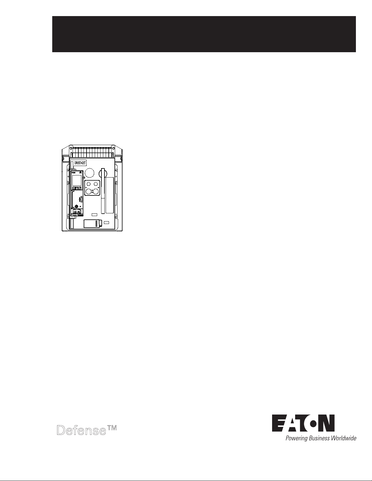
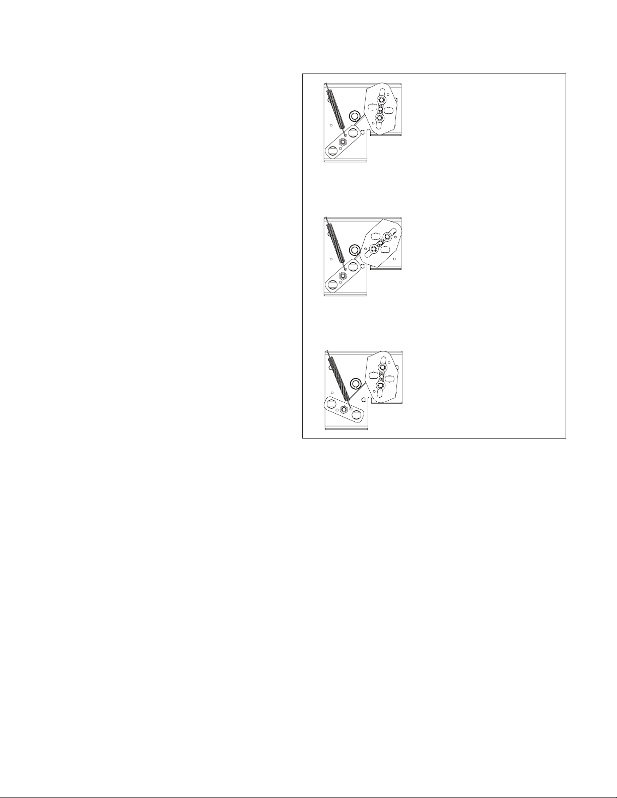
Driven ”And” lever
Driven lever
pull swivel
fitting
Driven lever
push swivel
fitting
Driven lever
push swivel
fitting
Drive lever
pull swivel
fitting
Drive
lever
Gap
Figure 10. Push and pull swivel fitting identification
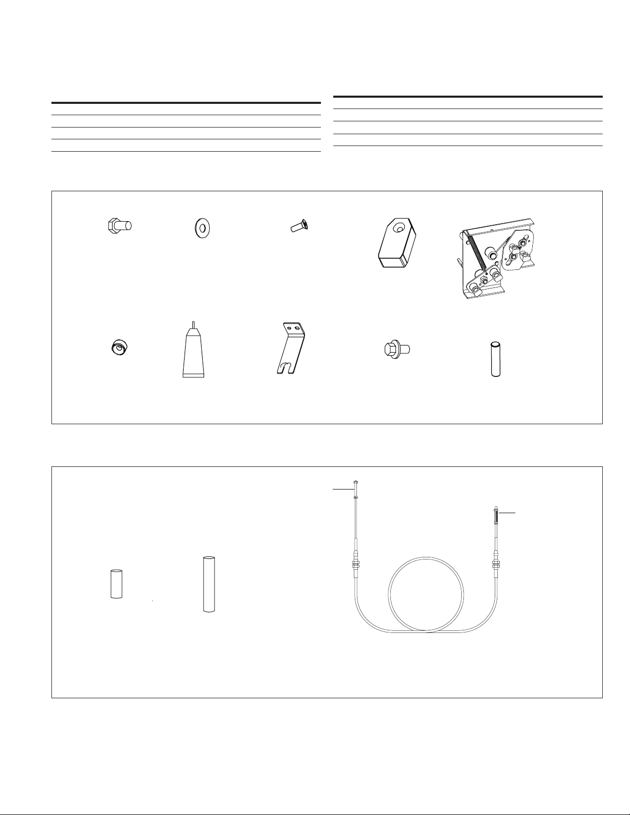
Step 6
This step describes how to first attach the drive (short rod) end of a
cable to its interlock assembly and cable bracket. See Figure 11.
To attach the drive (short rod) end of a cable to the drive lever pull
swivel fitting (refer to Figure 10), follow the directions below.
1. Remove upper nut, compression spring, and 38,1 mm (1,5 inch)
tube spacer from end of rod of cable assembly.
2. Slide rubber boot toward tip of rod.
3. Unthread outer bulkhead nut and slide nut and lock washer
toward tip.
4. Insert threaded end of rod into swivel fitting.
5. Slide smaller diameter portion of bulkhead fitting into cable
bracket slot, keeping one of the two lock washers with each
bulkhead nut.
6. Raise the cable assembly until threaded portion of bulkhead
fitting enters slotted hole in cable bracket (threads show
above bracket).
7. Bring bulkhead washer and nut down to threads and
hand tighten.
8. Adjust two bulkhead nuts to approximately center the threaded
section of the bulkhead fitting on the cable mounting bracket.
9. Hand tighten the bulkhead nuts at this time.
10. Slide rubber boot back into place over end of bulkhead fitting.
11. Replace 38,1 mm (1,5 inch) tube spacer, compression spring,
and upper nut on end of rod.
12. Lower nuts should be against the stop at the end of thread
and upper nut tightened against tube spacer.
13. Hold lower nuts and torque upper nut to 3,3–4,5 N·m
(30–40 in-lb).
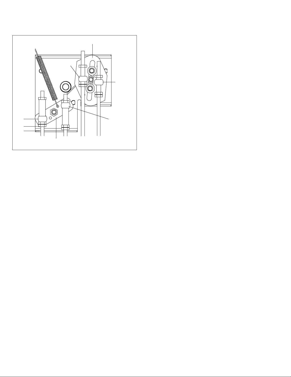
To attach the drive (short rod) end of a cable to the drive lever
push swivel fitting (refer to Figure 10), follow the directions below
(see Figure 11).
1. Remove upper nut from end of rod of cable assembly.
2. Slide rubber boot toward tip of rod.
3. Unthread outer bulkhead nut and slide nut and lock washer
toward tip.
4. Insert threaded end of rod with 38,1 mm (1,5 inch) tube spacer
into swivel fitting, ensuring that the compression spring remains
between the lower nuts and the swivel.
5. Slide smaller diameter portion of bulkhead fitting into cable
bracket slot, keeping one of the two lock washers with each
bulkhead nut.
6. Raise the cable assembly until threaded portion of bulkhead
fitting enters slotted hole in cable bracket (threads show
above bracket).
7. Bring bulkhead washer and nut down to threads and
hand tighten.
8. Adjust two bulkhead nuts to approximately center the threaded
section of the bulkhead fitting on the cable mounting bracket.
9. Hand tighten the bulkhead nuts at this time.
10. Slide rubber boot back into place over end of bulkhead fitting.
11. Lower nuts should be against the stop at the end of thread
and upper nut tightened against tube spacer.
12. Hold lower nuts and torque upper nut to 3,3–4,5 N·m
(30–40 in-lb).
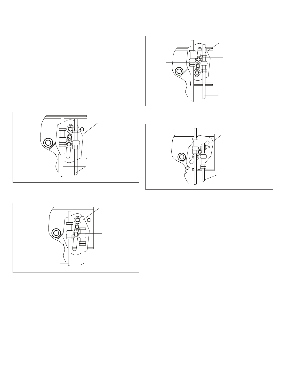
Step 7
This step describes how to attach the driven (long rod) end of a
cable attached to an interlock assembly on another breaker to the
cable bracket and interlock assembly on this Type NF frame breaker.
Refer to Figure 9 and Figure 10 for cable routing and correct swivel
fittings to which the cables are connected.
The driven (long rod) end of the cable is attached to the
corresponding push or pull swivel fitting on the driven lever on this
cable interlock assembly similarly to Step 6 except the driven end
does not utilize a compression spring between the swivel and nut.
For the push cable, remove and discard the 22,2 mm (0,875 inch)
cable tube spacer (M) on the rod end of the cable assembly (K) and
replace it with the 30,5 mm (1,2 inch) cable tube spacer (J). For the
pull cable, retain the 22,2 mm (0,875 inch) cable tube spacer (M) on
the rod end of the cable assembly (K). Install as shown in Figure 16.