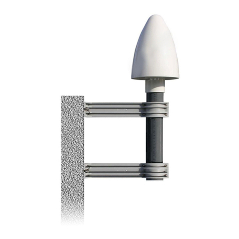
Meinberg GPSANTv2 User manual

MANUAL
GPSANTv2
GPS L1/Galileo E1 Antenna
July 24, 2023
Meinberg Funkuhren GmbH & Co. KG


Table of Contents
1 Imprint 1
2 Change Log 2
3 Copyright and Liability Exclusion 3
4 Presentation Conventions in this Manual 4
4.1 Conventions for the Presentation of Critical Safety Warnings .................... 4
4.2 Secondary Symbols Used in Safety Warnings ............................. 4
4.3 Conventions for the Presentation of Other Important Information .................. 5
4.4 Generally Applicable Symbols ...................................... 5
5 Important Safety Information 6
5.1 Appropriate Usage ............................................. 6
5.2 Product Documentation ........................................... 7
5.3 Safety during Installation ......................................... 7
5.4 Electrical Safety ............................................... 8
6 Important Product Information 9
6.1 CE Marking ................................................. 9
6.2 UKCA Marking ............................................... 9
6.3 Disposal ................................................... 10
7 Introduction 11
8 Before You Start 12
8.1 Contents of Delivery ............................................ 12
9 Antenna Installation 13
9.1 Selecting the Antenna Location ...................................... 13
9.2 Installation of the Antenna ......................................... 15
9.3 Antenna Cable ................................................ 17
9.4 Surge Protection and Grounding ..................................... 21
10 Technical Appendix 26
10.1 Technical Specifications: GPSANTv2 Antenna ............................. 26
10.2 Antenna Input: GPS Reference Clock .................................. 28
10.3 Antenna Input: GNS-UC Reference Clock ................................ 29
10.4 Antenna Short Circuit ........................................... 30
10.5 Technical Specifications: MBG-S-PRO Surge Protector ....................... 31
11 RoHS Conformity 32
12 Declaration of Conformity for Operation in the European Union 33
13 Declaration of Conformity for Operation in the United Kingdom 34
0

1 Imprint
1 Imprint
Meinberg Funkuhren GmbH & Co. KG
Lange Wand 9, 31812 Bad Pyrmont, Germany
Phone: + 49 (0) 52 81 / 93 09 - 0
Fax: + 49 (0) 52 81 / 93 09 - 230
Website: https://www.meinbergglobal.com
Email: [email protected]
Date: July 20, 2023
Manual
Version: 1.0
GPSANTv2 Date: July 24, 2023 1

2 Change Log
Version Date Revision Notes
———————————————————————————————————————————————
1.0 7/20/2023 Initial version
———————————————————————————————————————————————
2 Date: July 24, 2023 GPSANTv2

3 Copyright and Liability Exclusion
Except where otherwise stated, the contents of this document, including text and images of all types and transla-
tions thereof, are the intellectual property and copyright of Meinberg Funkuhren GmbH & Co. KG (“Meinberg”
in the following) and are subject to German copyright law. All reproduction, dissemination, modification, or ex-
ploitation is prohibited unless express consent to this effect is provided in writing by Meinberg. The provisions
of copyright law apply accordingly.
Any third-party content in this document has been included in accordance with the rights and with the consent
of its copyright owners.
A non-exclusive license is granted to redistribute this document (for example, on a website offering free-of-
charge access to an archive of product manuals), provided that the document is only distributed in its entirety,
that it is not modified in any way, that no fee is demanded for access to it, and that this notice is left in its
complete and unchanged form.
At the time of writing of this document, reasonable effort was made to carefully review links to third-party
websites to ensure that they were compliant with the laws of the Federal Republic of Germany and relevant
to the subject matter of the document. Meinberg accepts no liability for the content of websites not created or
maintained by Meinberg, and does not warrant that the content of such external websites is suitable or correct
for any given purpose.
While Meinberg makes every effort to ensure that this document is complete, suitable for purpose, and free
of material errors or omissions, and periodically reviews its library of manuals to reflect developments and
changing standards, Meinberg does not warrant that this specific document is up-to-date, comprehensive, or
free of errors. Updated manuals are provided at www.meinbergglobal.com and www.meinberg.support.
You may also write to [email protected] to request an updated version at any time or provide feedback
on errors or suggested improvements, which we are grateful to receive.
Meinberg reserves the right to make changes of any type to this document at any time as is necessary for
the purpose of improving its products and services and ensuring compliance with applicable standards, laws &
regulations.
GPSANTv2 Date: July 24, 2023 3

4 Presentation Conventions in this Manual
4.1 Conventions for the Presentation of Critical Safety Warnings
Warnings are indicated with the following warning boxes, using the following signal words, colors, and symbols:
Caution!
This signal word indicates a hazard with a low risk level. Such a notice refers to a procedure or other
action that may result in minor injury if not observed or if improperly performed.
Warning!
This signal word indicates a hazard with a medium risk level. Such a notice refers to a procedure or
other action that may result in serious injury or even death if not observed or if improperly performed.
Danger!
This signal word indicates a hazard with a high risk level. Such a notice refers to a procedure or
other action that will very likely result in serious injury or even death if not observed or if improperly
performed.
4.2 Secondary Symbols Used in Safety Warnings
Some warning boxes may feature a secondary symbol that emphasizes the defining nature of a hazard or risk.
The presence of an "electrical hazard" symbol is indicative of a risk of electric shock or
lightning strike.
The presence of a "fall hazard" symbol is indicative of a risk of falling when performing
work at height.
This "laser hazard" symbol is indicative of a risk relating to laser radiation.
4 Date: July 24, 2023 GPSANTv2

4 Presentation Conventions in this Manual
4.3 Conventions for the Presentation of Other Important Information
Beyond the above safety-related warning boxes, the following warning and information boxes are also used
to indicate risks of product damage, data loss, and information security breaches, and also to provide general
information for the sake of clarity, convenience, and optimum operation:
Important!
Warnings of risks of product damage, data loss, and also information security risks are indicated with
this type of warning box.
Information:
Additional information that may be relevant for improving efficiency or avoiding confusion or misunder-
standings is provided in this form.
4.4 Generally Applicable Symbols
The following symbols and pictograms are also used in a broader context in this manual and on the product.
The presence of the "ESD" symbol is indicative of a risk of product damage caused by
electrostatic discharge.
Direct current (DC) (symbol definition IEC 60417-5031)
Alternating current (AC) (symbol definition IEC 60417-5032)
Ground connection (symbol definition IEC 60417-5017)
Protective earth connection (symbol definition IEC 60417-5019)
GPSANTv2 Date: July 24, 2023 5

5 Important Safety Information
The safety information provided in this chapter as well as specific safety warnings provided at relevant
points in this manual must be observed during every installation and operation procedure of the antenna,
as well as its removal from service.
Any safety warnings affixed to the product itself must also be observed.
Any failure to observe this safety information, these safety warnings, and other safety-critical operating
instructions in the product documentation, or any other improper usage of the product may result in
unpredictable behavior from the product, and may result in injury or death.
Meinberg accepts no responsibility for injury or death arising from a failure to observe the safety
information, warnings, and safety-critical instructions provided in the product documentation.
It is the responsibility of the operator to ensure that the product is safely and properly used.
Should you require additional assistance or advice on safety-related matters for your product, Mein-
berg’s Technical Support team will be happy to assist you at any time. Simply send a mail to
5.1 Appropriate Usage
The device must only be used appropriately in accordance with the specifications of the product
documentation! Appropriate usage is defined exclusively by this manual as well as any other relevant
documentation provided directly by Meinberg.
Appropriate usage includes in particular compliance with specified limits! The device’s operating
parameters must never exceed or fall below these limits!
6 Date: July 24, 2023 GPSANTv2

5 Important Safety Information
5.2 Product Documentation
The information in this manual is intended for readers with an appropriate degree of safety awareness.
The following are deemed to possess such an appropriate degree of safety awareness:
•skilled persons with a familiarity with relevant national safety standards and regulations,
•instructed persons having received suitable instruction from a skilled person on relevant national
safety standards and regulations
If there is any safety information in the product documentation that you do not understand, do not
continue with the set-up or operation of the device!
Read the product manual carefully and completely before you set the product up for use.
Safety standards and regulations change on a regular basis and Meinberg updates the corresponding
safety information and warnings to reflect these changes. It is therefore recommended to visit the
Meinberg website at https://www.meinbergglobal.com regularly to download up-to-date manuals.
Please keep all product documentation, including this manual, in a safe place in digital or printed
format to ensure that it is always easily accessible.
additional assistance or advice on safety aspects of your Meinberg GPSANTv2 antenna.
5.3 Safety during Installation
If the antenna is to be installed at height, only use equipment that has been tested and is suitable for
reaching the location.
Always ensure that suitable personal protective equipment is worn when working at height!
Always ensure that health & safety standards are maintained!
Never work at height without a suitable and effective fall arrester!
Never mount, connect, disconnect, or dismantle an antenna while there is a risk of lightning strike!
Do not perform any work on antennas if it is not possible to maintain a safety distance from exposed
power lines or electrical substations.
GPSANTv2 Date: July 24, 2023 7

5.4 Electrical Safety
Never work on cables carrying a live current!
Never use cables or connectors that are visibly damaged or known to be defective! Faulty, defective, or
improperly connected shielding, connectors, or cables present a risk of injury or death due to electric
shock and may also constitute a fire hazard!
Before operating the device, check that all cables are in good order. Ensure in particular that the cables
are undamaged (for example, kinks), that they are not wound too tightly around corners, and that no
objects are placed on the cables.
Cables must be laid in such a way that they do not present a tripping hazard.
Never connect or disconnect power, data, or signal cables during a thunderstorm! Doing so presents
a risk of injury or death, as cables and connectors may conduct very high voltages in the event of a
lightning strike!
The device cables must be connected or disconnected in the order specified in the user documentation
for the device. Connect all cables only while the device is de-energized before you connect the power
supply.
Ensure that all plug connections are secure.
If the device malfunctions or requires servicing (for example, due to damage to the housing, power
supply cable, or the ingress of liquids or objects), the power supply may be cut off. In this case, the
device must be isolated immediately and physically from all power supplies! Electrical isolation must
be performed and confirmed in accordance with the following procedure:
8 Date: July 24, 2023 GPSANTv2

6 Important Product Information
6.1 CE Marking
This product bears the CE mark as is required to introduce the product into the EU
Single Market.
The use of this mark is a declaration that the product is compliant with all re-
quirements of the EU directives effective and applicable as at the time of manufacture of
the product. These directives are listed in the EU Declaration of Conformity, appended
to this manual as Chapter 12.
6.2 UKCA Marking
This product bears the British UKCA mark as is required to introduce the product into
the United Kingdom (excluding Northern Ireland, where the CE marking remains valid).
The use of this mark is a declaration that the product is in conformity with all
requirements of the UK statutory instruments applicable and effective as at the time
of manufacture of the product. These statutory instruments are listed in the UK
Declaration of Conformity, appended to this manual as Chapter 13.
GPSANTv2 Date: July 24, 2023 9

6.3 Disposal
Disposal of Packaging Materials
The packaging materials that we use are fully recyclable:
Material Use for Disposal
————————————————————————————————————————————-
Polystyrene Packaging frame/filling material Recycling Depot
(e.g., polystyrene peanuts)
PE-LD (Low-density polyethylene) Accessories packaging, bubble wrap Recycling Depot
Cardboard Shipping packaging, Paper Recycling
accessories packaging
For information on the proper disposal of packaging materials in your specific country, please inquire with your
local waste disposal company or authority.
Disposal of the Device
This product falls under the labeling obligations of the Waste Electrical and Electronic
Equipment Directive 2012/19/EU ("WEEE Directive") and thus bears this WEEE symbol.
The presence of this symbol indicates that this electronic product may only be disposed
of in accordance with the following provisions.
Important!
Do not dispose of the product via the household waste. Inquire with your local waste disposal company
or authority on how to best dispose of the product if necessary.
This product is considered to be a "B2B" product for the purposes of the WEEE Directive and is also classified
as "IT and Telecommunications Equipment" in accordance with Annex I of the Directive.
It can be returned to Meinberg for disposal. In this case, the shipping costs are to be borne by the cus-
tomer, while Meinberg will cover the costs for disposal. If you wish for Meinberg to handle disposal for you,
please get in touch with us. Otherwise, please use the return and collection systems provided within your
country to ensure that your device is disposed of in a compliant fashion to protect the environment and conserve
valuable resources.
10 Date: July 24, 2023 GPSANTv2

7 Introduction
7 Introduction
This manual is provided to assist you with the installation and proper connection of your Meinberg GPSANTv2.
Meinberg’s GPSANTv2 is a professional-grade single-band antenna for the reception of GPS or Galileo satellite
messages (time information and satellite status) on the GPS L1 and Galileo E1 transmission band of 1575.42
MHz. This makes it suitable for connection to a Meinberg GPS or GNS-UC reference clock to receive GPS L1
C/A code or Galileo E1 Open Service messages.
This latest-generation antenna is constructed to minimize interference caused by ground reflections, and thanks
to its vertical beam width of around 98 degrees, is less susceptible to jamming attacks. The integrated surge pro-
tector, constructed in accordance with IEC 61000-4-5 Level 4, protects the antenna from indirect surge sources
such as lightning strikes.
The antenna is integrated into Meinberg’s characteristic plastic casing, providing the internal electronics with
reliable protection against adverse conditions, including rainwater, snow, and other potentially harmful ele-
ments.
How It Works
Each satellite transmits all necessary navigation and system data over the carrier frequency. The conversion
unit integrated into the antenna converts the high-frequency phase-modulated spread spectrum signal received
from the GNSS satellites into a lower intermediate frequency (IF) of 35.4 MHz. The connected Meinberg
receiver processes the data received on this frequency to enable the position of the antenna to be determined
(requiring at least four satellites to be found) and the exact time to be determined, which in turn allows your
clock to be synchronized.
The antenna is connected to the reference clock using ordinary coaxial cable (such as RG58), and even longer
cable transmission distances can be traversed without the need for an additional amplifier.
Manual Revisions
Meinberg products are subject to ongoing development even after their market release, with new features
and enhancements added on a regular basis. Meinberg also revises its product manuals to account for these
feature updates.
GPSANTv2 Date: July 24, 2023 11

8 Before You Start
8.1 Contents of Delivery
3
5
2
4
6
4x 4x
4x
1
A delivery of a Meinberg GPSANTv2 antenna includes the following:
1. GPSANTv2 antenna
2. MBG S-PRO surge protector (optional)
3. RG58C/U antenna cable (optional)
4. Coaxial cable for surge protector (optional)
5. Tube mount and clips for Meinberg GPSANTv2 antenna
6. Mounting kit for Meinberg GPSANTv2 antenna
Unpack the GPSANTv2-Antenna and all accessories carefully and check the contents of the delivery against
the enclosed packing list to ensure that no parts are missing. If any of the listed items are missing, please
Check that the product has not been damaged in transit. If the product is damaged or fails to operate upon
installation, please contact Meinberg immediately. Only the recipient (the person or company receiving the
system) may file claims or complaints against the forwarder for damage caused in transit.
Meinberg recommends that you keep the original packaging materials in case the product needs to be shipped
or transported again at a later date.
12 Date: July 24, 2023 GPSANTv2

9 Antenna Installation
The following chapters explain how to select a suitable location for your antenna, how to fit the antenna, and
how to implement effective surge protection for your antenna installation.
9.1 Selecting the Antenna Location
There are essentially two ways the GPSANTv2 can be installed using the accessories included:
1. Mounted on a pole
2. Mounted on a wall
In either case, the location must be selected to ensure that the view of the sky is not obstructed in any
direction (see Fig .1) in order to ensure that enough satellites can be received.
To ensure that your antenna has the best 360◦view
possible, Meinberg recommends mounting the antenna
on a roof on a suitable metal pole (see Fig. 1, antenna
on right). If this is not possible, the antenna may be
mounted on the wall of a building, but must be high
enough above the edge of the roof (see Fig. 1, antenna
on left).
This prevents the line of sight between the antenna and
the satellites from being partially or fully obstructed
and limits the impact of GNSS signal reflections from
other surfaces such as house walls.
Antenna Cable
Clear view of the sky!
Wall-Mounted
Antenna
Pole-Mounted
Antenna
Building Entry
Point
Fig. 1: Ideal Positioning
GPSANTv2 Date: July 24, 2023 13

If there is a solid obstacle (a building or part of a
building) in the line of sight between the antenna and
each of the satellites (see Fig. 2), it is likely that the
satellite signals will be partially or fully obstructed
or reflected signals will cause interference, causing
problems with signal reception.
Wall-Mounted
Antenna
Fig. 2: Poor positioning of a
wall-mounted antenna
Other Installation Criteria for Optimum Operation:
•Vertical installation of antenna (see Fig. 1)
•At least 50 cm (1.5 ft) distance to other antennas
Information:
Problems may arise with the synchronization of your Meinberg time server if these conditions are not
met, as four satellites must be located to calculate the exact position.
14 Date: July 24, 2023 GPSANTv2

9 Antenna Installation
9.2 Installation of the Antenna
Please read the following safety information carefully before installing the antenna and ensure that it is ob-
served during the installation.
Danger!
Do not mount the antenna without an effective fall arrester!
Danger of death from falling!
•Ensure that you work safely when installing antennas!
•Never work without an effective fall arrester!
Danger!
Do not work on the antenna system during thunderstorms!
Danger of death from electric shock!
•Do not carry out any work on the antenna system or the antenna cable if there is a risk of
lightning strike.
•Do not carry out any work on the antenna system if it is not possible to maintain the prescribed
safe distance to exposed lines and electrical substations.
GPSANTv2 Date: July 24, 2023 15

Mount the GPSANTv2 (as shown in Fig. 3) at a distance of at least 50 cm to other antennas using the mounting
kit provided, either onto a vertical pole of no more than 60 mm diameter or directly onto a wall.
Fig. 3: Mounting a GPSANTv2 antenna onto a pole
Fig. 3 illustrates the mounting of a GPSANTv2 on a pole by way of example. When mounting the antenna on
a wall, the four wall plugs and M6x45 screws should be used to mount the two halves of the pole clamp (Fig.
3, Pos. 9) using the provided screw slits.
The next chapter explains how the antenna cable should be laid.
16 Date: July 24, 2023 GPSANTv2

9 Antenna Installation
9.3 Antenna Cable
Selecting the Appropriate Cable
Meinberg provides suitable cable types with its antennas and these are ordered together with the antenna
to match the length you need from your antenna to your Meinberg reference clock. The route to be covered
for your antenna installation should be determined and the appropriate cable type selected accordingly before
confirming your order.
The cable is shipped with both ends fitted with the appropriate connectors as standard, although the cable
can also be shipped without any pre-fitted connectors if so requested.
The table below shows the specifications of the supported cable types for the transmission of the 35 MHz
intermediate frequency:
Cable Type
RG58C/U
RG213
H2010 (Ultraflex)
Signal Propagation Time
at 35 MHz
503.6
509.61
387.45
Attenutation at 35 MHz
(dB/100 m)
8.48
3.46
2.29
(Ohm/100 m)
DC Resistance
5.3
1.0
1.24
Cable Diameter (mm)
5
10.3
7.3
Max. Cable Length (m)
300
700
1100
Tab. 1: Specifications of Cable Types Recommended by Meinberg
* The propagation times are specified on the basis of 100 m cable; these values can be used as a refer-
ence to calculate the propagation time of any other arbitrary length of cable.
Important!
Please avoid using a mixture of different cable types for your antenna installation. This should be
taken into consideration in particular when purchasing additional cable, for example to extend an
existing cable installation.
GPSANTv2 Date: July 24, 2023 17
This manual suits for next models
2
Table of contents
Other Meinberg Antenna manuals