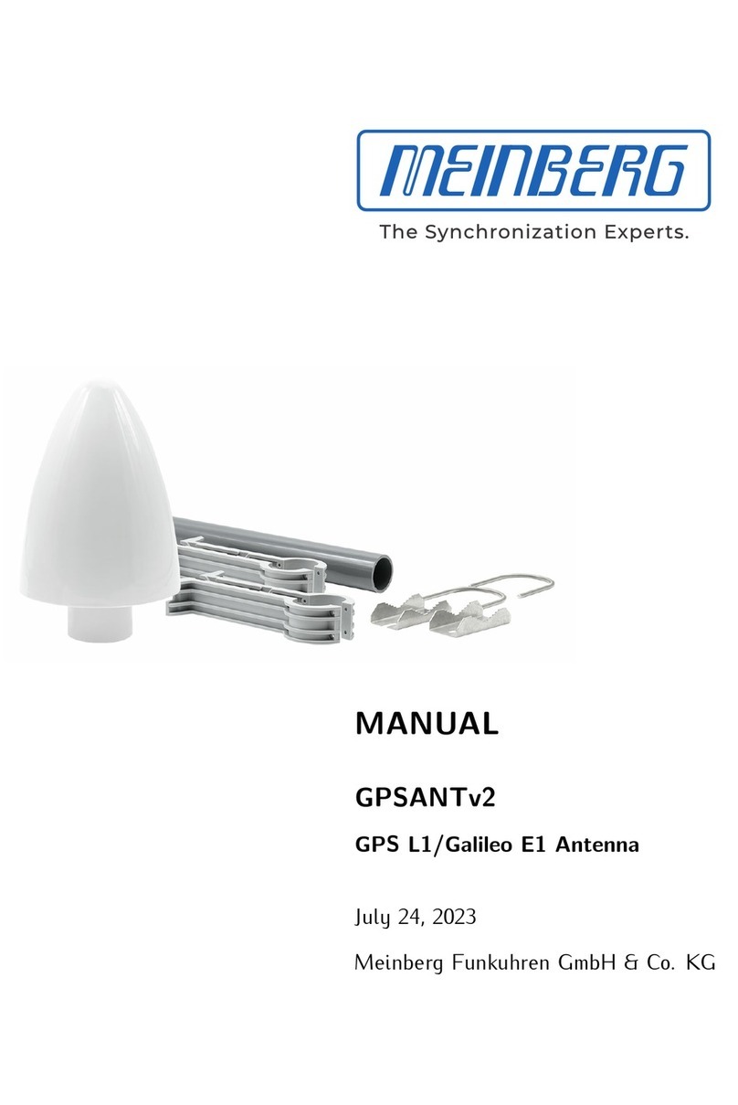
Meinberg GNSS MULTI BAND Antenna User manual

MANUAL
GNSS MULTI BAND Antenna
Antenna / Converter Unit
25th February 2020
Meinberg Funkuhren GmbH & Co. KG


Table of Contents
1 Imprint 1
2 Safety Hints Antenna 2
3 Before you start 3
3.1 Scope of delivery ............................................... 3
3.2 Disposal of Packaging Materials ...................................... 4
4 Installation GNSS Multiband Antenna 5
5 Technical Specifications GNSS Multiband Antenna 9
5.1 MBG S-PRO - Technical Specifications ................................. 11
5.1.1 MBG S-PRO - Physical Dimensions ............................... 13
5.1.2 Installation and Grounding ..................................... 13
6 RoHS and WEEE 14
7 EU Declaration of Conformity 15
Date: 25th February 2020 GNSS MULTI BAND Antenna

1 Imprint
1 Imprint
Meinberg Funkuhren GmbH & Co. KG
Lange Wand 9, 31812 Bad Pyrmont / Germany
Phone: + 49 (0) 52 81 / 93 09 - 0
Fax: + 49 (0) 52 81 / 93 09 - 230
Internet: https://www.meinbergglobal.com
Mail: [email protected]
Date: 2020-02-25
GNSS MULTI BAND Antenna Date: 25th February 2020 1

2 Safety Hints Antenna
WARNING!
DANGER TO LIFE BY ELECTRICAL SHOCK!
Make sure to comply with the occupational health and safety standards when installing the antenna. Never
work without a proper fall protection device!
Do not carry out any installation or maintenance work on the antenna system or cabling when there is a
potential risk of lightning.
Surge Voltage Protector
Due to extremely high currents associated with lightning no surge protection device can provide absolute safety
from the impacts caused by lightning!
2 Date: 25th February 2020 GNSS MULTI BAND Antenna

3 Before you start
3 Before you start
3.1 Scope of delivery
3
5
2
4
6
4x 4x
4x
1
Included in delivery of a Meinberg GNSS Multi Band antenna:
1. GNSS Multi Band antenna
2. Surge voltage protector (optional)
3. 20 m Antenna cable Belden H155
4. Coax cable for surge voltage protector (optional)
5. Retaining tube and clips for Meinberg GNSS Multi Band antenna
6. Mounting kit for Meinberg Meinberg GNSS Multi Band antenna
Carefully unpack the system and all accessories and put them aside. Check the scope of delivery with the pack-
ing list to ensure that no parts are missing. If any of the listed contents are missing, please contact Meinberg
Funkuhren.
Check the system for shipping damage. If the system is damaged or cannot be put into operation, contact
Meinberg Funkuhren immediately. Only the recipient (the person or company receiving the system) can assert
a claim against Freight Forwarder for shipping damage.
Meinberg recommends that you keep the original packaging materials for possible future transport.
GNSS MULTI BAND Antenna Date: 25th February 2020 3

3.2 Disposal of Packaging Materials
The packaging materials we use are fully recyclable:
Material Use for Disposal
————————————————————————————————————————
Polystyrol packaging frame/filling material Recycling Depot
(polystyrene peanuts, bubble wrap)
PE-LD accessories packaging Recycling Depot
Polyethylene
low density
Cardboard shipping packaging, Paper recycling
accessories packaging
————————————————————————————————————————
4 Date: 25th February 2020 GNSS MULTI BAND Antenna

4 Installation GNSS Multiband Antenna
WARNING!
Antenna mounting without effective anti-fall protection
Danger to life due to fall!
- Pay attention to effective working safety when installing antennas!
- Never work without an effective anti-fall equipment!
WARNING!
Working on the antenna system during thunderstorms
Danger to life due to electrical shock!
- Do not carry out any work on the antenna system or the antenna cable
if there is a risk of a lightning strike.
- Do not carry out any work on the antenna system if the safety distance
to free lines and sequential circuits is exceeded.
1. Selection of the Antenna location
To receive enough satellites, select a location that allows an unobstructed view of the sky, otherwise there
may be problems with the synchronization of the system. There should be no obstacle in the line of sight
between the antenna and the satellites. In addition, the antenna must not be installed under high-voltage lines
or other electrical light or electric circuits.
Installation conditions for optimal operation:
•Free view from 8◦above the horizon or
•free view towards equator (if free view of 8◦not possible) or
•clear view between 55th southern and 55th northern latitude (satellite orbits).
If this view is also restricted, there may be complications in case four
satellites have to be found for a calculation of a new position.
GNSS MULTI BAND Antenna Date: 25th February 2020 5

Antenna Mounting
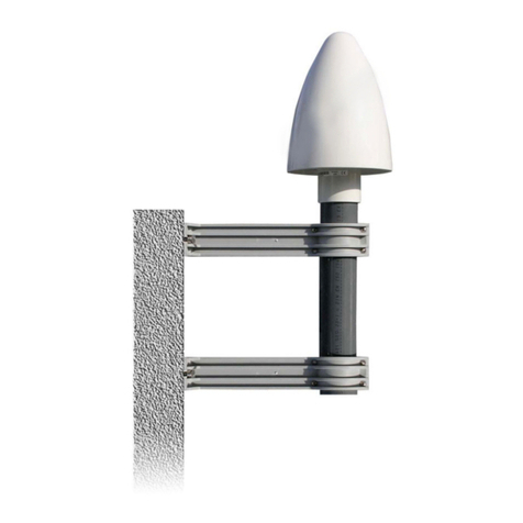
1.
Mount the antenna at a minimum distance of 50 cm
from other antennas to an vertical pole up to 60 mm
outer diameter or on a wall with the mounting kit in-
cluded in the scope of delivery.
Then connect the antenna cable (Belden H155) to
the N-Norm connector of the antenna. Lead the other
end of the cable through the wall into the building.
GNSS Antenna
N-Norm (female)
N-Norm (male)
Free view to the sky!
Make sure that the maximum cable length is kept when installing the antenna
cable between the antenna and receiver. This depends on the type of cable
used (H155, RG58) and its damping factor.
6 Date: 25th February 2020 GNSS MULTI BAND Antenna

4 Installation GNSS Multiband Antenna
2.
The optional overvoltage protection MBG S-PRO can
be mounted now. This is also suitable for outdoor in-
stallation (protection class: IP55). However, Meinberg
recommends an installation in closed rooms, just after
the antenna cable has entered the wall, in order to
reduce the risk of overvoltage damage, e.g. due to
lightning strikes.
Connect the other side of the antenna cable to the
surge protection socket.
N-Norm (male)
N-Norm (female)
Outside wall of the building
Outdoor installation
Inside a waterproof housing.
Indoor installation
(recommended)
Just after the antenna cable enters
N-Norm (female)
N-Norm (male)
MBG S-PRO
MBG S-PRO
the wall.
3.
The next step is to connect the supplied coaxial cable
between the surge protector and receiver.
N-Norm (female)
N-Norm (male)
SMA (female)
BNC (female)
N-Norm (male)
N-Norm (female)
BNC (male)
Receiver
Antenna splitter
SMA (male)
GNSS
MBG S-PRO
Optional
GNSS MULTI BAND Antenna Date: 25th February 2020 7

Antenna splitter option
Several receivers can be connected to one antenna via the antenna splitter. Make sure, that the total length of
a route going from the antenna via the splitter to the receiver, does not exceed the maximum cable length. The
splitter can be installed at any position between antenna or, if used, the surge protector and receiver.
Receiver
Antenna splitter
Antenna
GNSS
GNSS
In
Out 3
Out 1
Out 2
Out 4
Route AB = 65 m (H155) - Total length „OK“
Route AC = 110 m (H155) - max. total length exceeded
A
B
C
Compensation the signal propagation time of the antenna cable
The receiving satellite signal is delayed by the used coaxial cable. The connected receiver must compen-
sate the signal propagation time of the antenna cable, therefore you need to enter the length of the antenna
cable in meters or the compensation time in nanoseconds into the settings of your receiver.
Antenna Cable Length (m):
Cable Delay Usage
RG58U 5 ns/m for GPS180 and GNS-UC
H155 4 ns/m for GNS180 and GNM
By entering the cable length (from antenna to receiver), the system calculates the delay time and compen-
sates it automatically.The default value of 20 m is preconfigured at delivery.
For other coaxial cable types please use the option "by delay". The delay must be calculated by yourself
by using the information in the data sheet of the respective coaxial cable.
8 Date: 25th February 2020 GNSS MULTI BAND Antenna

5 Technical Specifications GNSS Multiband Antenna
5 Technical Specifications GNSS Multiband
Antenna
Physical Dimensions:
GNSS MULTI BAND Antenna Date: 25th February 2020 9

Specifications:
Power supply: 5 V - 16 V, 24 mA (via antenna cable)
Antenna-
input GNSS: Antenna circuit insulated, dielectric strenght 1000V
Frequency ranges: 1164 MHz to 1254 MHz and 1525 MHz to 1606 MHz
Overall LNA gain: 37 dB typ, 35 dB min
LNA noise figure: 2.5 dB typ at 25 ◦C
Supported frequency bands:
GPS L1/L2/L5
GLONASS G1/G2/G3
Beidou B1/B2
Galileo E1/E5a+b plus L-band
Out-of-band rejection:
Freq. Band L5/E5/L2/G2 Frequency Gain
< 1050 MHz > 45 dB
< 1125 MHz > 30 dB
< 1350 MHz > 45 dB
Freq. Band L1/E1/B1/G1 Frequency Gain
< 1450 MHz > 30 dB
< 1690 MHz > 30 dB
< 1730 MHz > 40 dB
Connector: N-Norm, female
Form factor: ABS plastic case for outdoor installation
Protection class: IP66
Humidity: 95%
Temperature range: -40 ◦C to +85 ◦C (-40 to 185 ◦F)
Weight: 1.6 kg (3.53 lbs) incl. mounting kit
10 Date: 25th February 2020 GNSS MULTI BAND Antenna

5 Technical Specifications GNSS Multiband Antenna
5.1 MBG S-PRO - Technical Specifications
Attachment plug with replaceable gas discharge tube for coaxial signal interfaces. Connection: N connector
female/female. The MBG S-PRO set includes a surge voltage protector (Phoenix CN-UB-280DC-BB), a pre-
assembled coax cable and a mounting bracket.
The surge voltage protector for coaxial lines has to be installed in the antenna line. The shield has to be
connected to earth as short as possible. CN-UB-280DC-BB is equipped with two type-N female connectors.
It has no dedicated input/output polarity or prefered mounting orientation.
Phoenix CN-UB-280DC-BB
Features:
•High RF Performance
•Multiple Strike Capability
•20 kA Surge Protection
•Bi-directional Protection
Mounting type Connection-specific intermediate plugging
Type Attachment plug
Direction of action Line-Shield/Earth Ground
Maximum continuous
operating voltage UC (wire-ground) 280 V DC
195 V AC
Nominal current IN5 A (25 ◦C)
Operating effective current IC at UC ≤1µA
Nominal discharge current In (8/20) µs (Core-Earth) 20 kA
In (8/20) µs (Core-Shield) 20 kA
Total surge current (8/20) µs 20 kA
(10/350) µs 2,5 kA
GNSS MULTI BAND Antenna Date: 25th February 2020 11

Max. discharge current Imax (8/20)µs maximum (Core-Shield) 20 kA
Nominal pulse current Ian (10/1000)µs (Core-Shield) 100 A
Impulse discharge current (10/350) µs, peak value Iimp 2,5 kA
Output voltage limitation at 1 kV/µs (Core-Earth) spike ≤900 V
at 1 kV/µs (Core-Earth) spike ≤900 V
Response time tA (Core-Earth) ≤100 ns
tA (Core-GND) ≤100 ns
Input attenuation aE, asym. typ. 0.1 dB (≤1.2 GHz)
typ. 0.2 dB (≤2.2 GHz)
Cut-off frequency fg (3 dB), asym. (shield) in 50 Ohm system > 3 GHz
Standing wave ratio SWR in a 50 Ωsystem typ. 1.1 (≤2 GHz)
Permissible HF power Pmax at VSWR = xx (50 ohm system) 700 W (VSWR = 1.1)
200 W (VSWR = ∞)
Capacity (Core-Earth) typ. 1,5 pF
asymmetrical (shield) typ. 1,5 pF
Surge current resistance (conductor-ground) C1 - 1 kV/500 A
C2 - 10 kV/5 kA
C3 - 100 A
D1 - 2,5 kA
Ambient temperature (operation) -40 ◦C ... 80 ◦C
Altitude ≤2000 m (above sea level)
Degree of protection IP55
Housing material Nickel-plated brass
Color nickel
Dimensions Height 25 mm, Width 25 mm, Depth 67 mm
Connection data N-Connector 50 Ohm
IN N-Connector Buchse
OUT N-Connector Buchse
Standards/regulations IEC 61643-21 2000 + A1:2008
EN 61643-21 2001 + A1:2009
Source: PHOENIXCONTACT.COM Surge Voltage Protector - CN-UB-280DC-BB
12 Date: 25th February 2020 GNSS MULTI BAND Antenna

5 Technical Specifications GNSS Multiband Antenna
5.1.1 MBG S-PRO - Physical Dimensions
67 11
15,8
25
13,4
5.1.2 Installation and Grounding
GNSS MULTI BAND Antenna Date: 25th February 2020 13

6 RoHS and WEEE
Compliance with EU Directive 2011/65/EU (RoHS)
We hereby declare that this product is conform to the
European Directive 2011/65/EU and its delegated di-
rective 2015/863/EU “Restrictions of Hazardous Sub-
stances in Electrical and Electronic Equipment”. We
ensure that electrical and electronic products sold in
the EU do not contain lead, cadmium, mercury, hex-
avalent chromium, polybrominated biphenyls (PBBs),
and polybrominated diphenyl ethers (PBDEs), Bis
(2-ethylhexyl)phthalat (DEHP), Benzylbutylphthalat
(BBP), Dibutylphthalat (DBP), Diisobutylphthalat
(DIBP), above the legal threshold.
WEEE status of the product
This product is handled as a B2B (Business to Busi-
ness) category product. In order to secure a WEEE
compliant waste disposal it has to be returned to the
manufacturer. Any transportation expenses for return-
ing this product (at its end of life) have to be incurred
by the end user, whereas Meinberg will bear the costs
for the waste disposal itself.
14 Date: 25th February 2020 GNSS MULTI BAND Antenna

7 EU Declaration of Conformity
Konformitätserklärung
Doc ID: -2020-02-25
Hersteller Meinberg Funkuhren GmbH & Co. KG
Manufacturer Lange Wand 9, D-31812 Bad Pyrmont
erklärt in alleiniger Verantwortung, dass das Produkt,
declares under its sole responsibility, that the product
Produktbezeichnung GNSS Multi Band Antenna
Product Designation
auf das sich diese Erklärung bezieht, mit den folgenden Normen und Richtlinien übereinstimmt:
to which this declaration relates is in conformity with the following standards and provisions of the directives:
——————————————————————————————————————————————-
RED – Richtlinie ETSI EN 303 413 V1.1.1 (2017-06)
RED – Directive
2014/53/EU
——————————————————————————————————————————————-
EMV – Richtlinie Draft ETSI EN 301 489-1 V2.2.0 (2011-09)
EMC – Directive Draft ETSI EN 301 489-19 V2.1.0 (2011-09)
DIN EN 61000-6-2:2005
2014/30/EU DIN EN 61000-6-3:2007 + A1:2011
DIN EN 55032:2015
DIN EN 55024:2010
——————————————————————————————————————————————-
Niederspannungsrichtlinie DIN EN 60950-1:2006 + A11:2009 + A1:2010 + A12:2011 +
Low-voltage Directive AC:2011 + A2:2013
2014/35/EU
——————————————————————————————————————————————-
RoHS – Richtlinie DIN EN 50581:2012
RoHS – Directive
2011/65/EU + 2015/863/EU
——————————————————————————————————————————————-
Bad Pyrmont, den 2020-02-25
GNSS MULTI BAND Antenna Date: 25th February 2020 15
Table of contents
Other Meinberg Antenna manuals
Popular Antenna manuals by other brands

KVH Industries
KVH Industries TracPhone V11IP Reshipping Instructions

Antenna Specialists
Antenna Specialists Constellation On-Glass user guide

WaveForm
WaveForm 2x2 MIMO quick start guide

CUSHCRAFT
CUSHCRAFT R6000 Assembly and installation instructions

H3C
H3C ANT-2510P-M4 user guide

Javad
Javad TRIUMPH-1M Plus quick start guide

Diamond Antenna
Diamond Antenna D130J operating manual

AOR
AOR LA800 instruction manual

Feig Electronic
Feig Electronic ID ISC.ANT800/600 Installation and tuning guide

Cisco
Cisco 3G-ANTM1916-CM manual

Winegard
Winegard AIR 360+ quick start guide

Precision Digital Corporation
Precision Digital Corporation Yagi PDWA3900 instruction manual