Meinberg GPS Antenna User manual

MANUAL
GPS Antenna
Antenna / Converter Unit
16th February 2015
Meinberg Radio Clocks GmbH & Co. KG


Page 0
Table of Contents
1 Safety Hints Antenna 1
2 Meinberg GPS Antenna/Converter Unit 2
2.1 MountingtheGPSAntenna...................................... 4
2.1.1 Example:............................................ 4
2.1.2 Antenna Assembly with Surge Voltage Protection . . . . . . . . . . . . . . . . . . . . . . 5
2.1.3 AntennaShort-Circuit..................................... 6
2.2 MBG S-PRO - Technical Specications . . . . . . . . . . . . . . . . . . . . . . . . . . . . . . . . 7
2.2.1 MBG S-PRO - Physical Dimensions . . . . . . . . . . . . . . . . . . . . . . . . . . . . . 9
2.2.2 Installation and Grounding . . . . . . . . . . . . . . . . . . . . . . . . . . . . . . . . . . 9
2.3 FeaturesofGOAL........................................... 10
0
Date: 16th February 2015 GPS Antenna

Page 1
1 Safety Hints Antenna
WARNING!
DANGER TO LIFE BY ELECTRICAL SHOCK!
Make sure to comply with the occupational health and safety standards when installing the antenna. Never
work without a proper fall protection device!
Do not carry out any installation or maintenance work on the antenna system or cabling when there is a po-
tential risk of lightning.
Surge Voltage Protector
Due to extremely high currents associated with lightning no surge protection device can provide absolute safety
from the impacts caused by lightning!
GPS Antenna Date: 16th February 2015
1

Page 2 2 Meinberg GPS Antenna/Converter Unit
2 Meinberg GPS Antenna/Converter Unit
- Antenna/Converter Unit
- Preformed Cable
- Holder for Wall Mounting
- Clamps for Pole Mounting
- Optional: Voltage Protector
Antenna: Antenna/converter unit with remote power supply
Length of cable: Refer to chapter "Mounting the Antenna"
Antenna
Input GPS: Antenna circuit 1000 V DC insulated
Receiver Input
Frequency: 1575.42 MHz (L1)
Local Oscillator
to Converter
Frequency: 10 MHz
1
First IF
Frequency: 35.4 MHz
1
Connector: female type-N
Protection
Class: IP66
Ambient
Temperature: -40
◦
C ... +65
◦
C
Humidity: 95%
Weigth: 420g (without accessories)
(1)
these frequencys are transfered via the antenna cable.
Power Requirements: 12V ... 18V, 100mA (via antenna cable)
2
Date: 16th February 2015 GPS Antenna

Page 3
Physical Dimensions:
4444
240240
140140
450450
7070
M6M6
180180
6868
8484
66
GPS Antenna Date: 16th February 2015
3

Page 4 2 Meinberg GPS Antenna/Converter Unit
2.1 Mounting the GPS Antenna
The GPS satellites are not stationary, but circle round the globe with a period of about 12 hours. They can only
be received if no building is in the line-of-sight from the antenna to the satellite, so the antenna/downconverter
unit must be installed in a location that has as clear a view of the sky as possible. The best reception is achieved
when the antenna has a free view of 8
◦
angular elevation above the horizon. If this is not possible, the antenna
should be installed with the clearest free view to the equator, because the satellite orbits are located between
latitudes 55
◦
North and 55
◦
South. If this is not possible, you may experience diculty receiving the four satellites
necessary to complete the receiver's position solution.
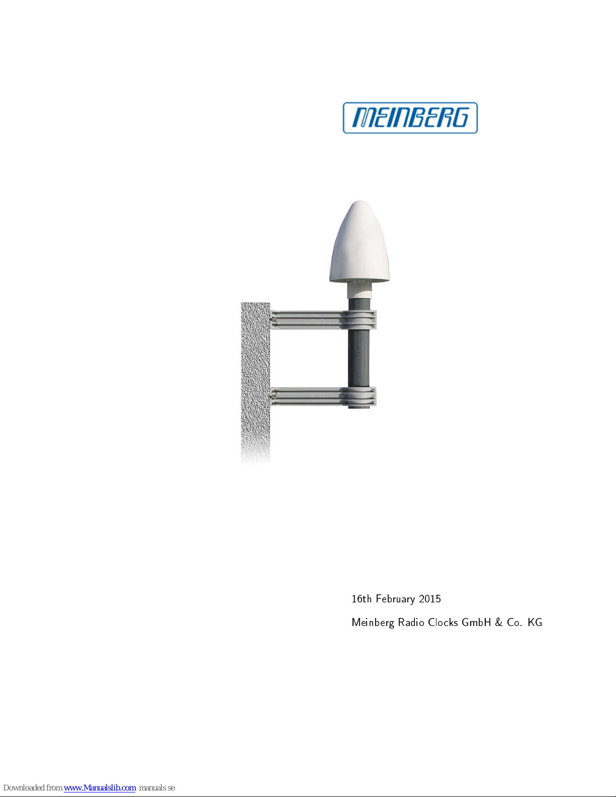
The antenna/converter unit can be mounted on a wall, or on a pole up to 60 mm in diameter. A 50 cm
plastic tube, two wall-mount brackets, and clamps for pole mounting are included. A standard RG58 coaxial
cable should be used to connect the antenna/downconverter unit to the receiver. The maximum length of cable
between antenna and receiver depends on the attenuation factor of the coaxial cable.
Up to four receivers can be run with one antenna/downconverter unit by using an optional antenna splitter.
The total length of an antenna line from antenna to receiver must not be longer than the max. length shown in
the table below. The position of the splitter in the antenna line does not matter.
High voltage protectors must be installed directly after reaching the indoors. The optional delivered protec-
tion kit is not for outdoor usage.
2.1.1 Example:
Type of cable diameter Ø Attenuation at 100MHz max lenght.
[mm] [dB]/100m [m]
RG58/CU 5mm 17 300
(1)
RG213 10.5mm 7 700
(1)
(1)This specications are made for antenna/converter units produced after January, 2005
The values are typically ones; the exact ones are to nd out from the data sheet of the used cable
4
Date: 16th February 2015 GPS Antenna

2.1 Mounting the GPS Antenna Page 5
2.1.2 Antenna Assembly with Surge Voltage Protection
Optional a surge voltage protector for coaxial lines is available. The shield has to be connected to earth as short
as possible by using the included mounting bracket. Normally you connect the antenna converter directly with
the antenna cable to the system.
GPS Antenna Date: 16th February 2015
5

Page 6 2 Meinberg GPS Antenna/Converter Unit
2.1.3 Antenna Short-Circuit
(systems with front display only)
In case of an antenna line short-circuit the following message appears in the display:
ANTENNA
SHORT-CIRCUIT
DISCONNECT POWER
! ! !
If this message appears the clock has to be disconnected from the mains and the defect eliminated. After that
the clock can be powered-up again. The antenna supply voltage must be 15V
DC
.
6
Date: 16th February 2015 GPS Antenna

2.2 MBG S-PRO - Technical Specications Page 7
2.2 MBG S-PRO - Technical Specifications
Attachment plug with replaceable gas discharge tube for coaxial signal interfaces. Connection: N connector fe-
male/female. The MBG S-PRO set includes a surge voltage protector (Phoenix CN-UB-280DC), a pre-assembled
coax cable and a mounting bracket.
The surge voltage protector for coaxial lines has to be installed in the antenna line. The shield has to be
connected to earth as short as possible. CN-UB-280DC is equipped with two type-N female connectors. It has
no dedicated input/output polarity or prefered mounting orientation.
Phoenix CN-UB-280DC
Features:
•
High RF Performance
•
Multiple Strike Capability
•
20 kA Surge Protection
•
Bi-directional Protection
•
Rugged and Waterproof
Mounting type
Connection-specic intermediate plugging
Type
Attachment plug
Direction of action
Line-Shield/Earth Ground
Maximum continuous
operating voltage
UC (wire-ground) 280 V DC
195 V AC
Nominal current
IN 5 A (25
◦
C)
Operating eective current
IC at UC
≤
1
µ
A
Nominal discharge current
In (8/20)
µ
s (Core-Earth) 20 kA
Nennableitstoÿstrom
In (8/20)
µ
s (Core-Shield) 20 kA
Total surge current
(8/20)
µ
s 20 kA
Total surge current
(10/350)
µ
s 2,5 kA
GPS Antenna Date: 16th February 2015
7

Page 8 2 Meinberg GPS Antenna/Converter Unit
Max. discharge current
Imax (8/20)
µ
s maximum (Core-Shield) 20 kA
Nominal pulse current
Ian (10/1000)
µ
s (Core-Shield) 100 A
Impulse discharge current
(10/350)
µ
s, peak value Iimp 2,5 kA
Output voltage limitation
at 1 kV/
µ
s (Core-Earth) spike
≤
900 V
Output voltage limitation
at 1 kV/
µ
s (Core-Earth) spike
≤
900 V
Response time
tA (Core-Earth)
≤
100 ns
Response time
tA (Core-GND)
≤
100 ns
Input attenuation
aE, asym. typ. 0.1 dB (
≤
1.2 GHz)
typ. 0.2 dB (
≤
2.2 GHz)
Cut-o frequency
fg (3 dB), asym. (shield) in 50 Ohm system > 3 GHz
Standing wave ratio
SWR in a 50
Ω
system typ. 1.1 (
≤
2 GHz)
Permissible HF power
Pmax at VSWR = xx (50 ohm system) 700 W (VSWR = 1.1)
200 W (VSWR =
∞
)
Capacity
(Core-Earth) typ. 1,5 pF
Capacity
asymmetrical (shield) typ. 1,5 pF
Surge current resistance
(conductor-ground) C1 - 1 kV/500 A
C2 - 10 kV/5 kA
C3 - 100 A
D1 - 2,5 kA
Ambient temperature
(operation) -40
◦
C ... 80
◦
C
Degree of protection
IP55
Housing material
Nickel-plated brass
Color nickel
Dimensions
Height 25 mm, Width 25 mm, Depth 67 mm
Connection data
N-Connector 50 Ohm
IN N-Connector Buchse
OUT N-Connector Buchse
Standards/regulations
IEC 61643-21
Source: PHOENIXCONTACT.COM Surge Voltage Protector - CN-UB-280DC-BB
8
Date: 16th February 2015 GPS Antenna

2.2 MBG S-PRO - Technical Specications Page 9
2.2.1 MBG S-PRO - Physical Dimensions
67 11
15,8
25
13,4
2.2.2 Installation and Grounding
GPS Antenna Date: 16th February 2015
9

Page 10 2 Meinberg GPS Antenna/Converter Unit
2.3 Features of GOAL
GOAL is a GPS Optical Antenna Link set for connecting
a Meinberg GPS antenna to a Meinberg GPS receiver
via one optical multimode ber. The module GOAL/R
is to connect to the receivers antenna input via a patch
cable and can be assembled somewhere around. The
module GOAL/A is to mount indoor, connected to the
Meinberg antenna via a coaxial cable.
Both modules are linked to each other via a single
GI50/125
µ
m or GI62,5/125
µ
m multimode gradient
ber.
This kind of connection provides several advantages:
- large antenna cable distances (up to 2000 mtrs.)
- no destructive overvoltage via the antenna cable
- no unintentional monitoring via optical ber
The receiver-side module GOAL/R is supplied with power via the antenna input connector of the GPS receiver,
therefore no external power supply is necessary. The module GOAL/A needs an external supply for operating
and feeding the GPS antenna. Whenever the antenna is not connected, or a short circuit occurs on the antenna
cable, this is shown by a status LED in the front panel. A second status LED shows that the 10MHz reference
clock, coming from the GOAL/R, is received within a sucient signal strength and therefore the FO link is working.
The GOAL system is suitable for all Meinberg GPS receivers (except GPS166!), also for the later extension
of existing systems. When using the GOAL system together with the GPS signal converter GPSGEN1575 it is to
be noted that operation of connected GPS receivers from third-party manufacturers can not be guaranteed!
Physical Dimensions:
GOAL/A: 44mm x 105mm x 165mm (height x width x depth)
GOAL/R: 25mm x 25mm x 95mm (height x width x depth)
10
Date: 16th February 2015 GPS Antenna

Konformitätserklärung
Declaration of Conformity
Doc ID: GPSANT-02092014
Hersteller Meinberg Funkuhren GmbH & Co. KG
Manufacturer Lange Wan 9
D-31812 Ba Pyrmont
erklärt n alle n ger Verantwortung, daß das Produkt
declares under ts sole respons b l ty, that the product
Produktbeze chnung GPSANT
Product Des gnat on
auf das s ch d ese Erklärung bez eht, m t den folgenden Normen übere nst mmt
to wh ch th s declarat on relates s n conform ty w th the follow ng standards
EN55022:2010, Class B L m ts and methods of measurement of rad o nterference
character st cs of nformat on technology equ pment
EN55024:2010 L m ts and methods of measurement of Immun ty character st cs of
nformat on technology equ pment
EN 50581:2012 Techn cal documentat on for the assessment of electr cal and electron c
products w th respect to the restr ct on of hazardous substances
gemäß den R chtl n en 2004/108/EG (Elektromagnet sche Verträgl chke t), 2006/95/EG
(N ederspannungsr chtl n e), 2011/65/EU (Beschränkung der Verwendung best mmter gefährl cher
Stoffe) und 93/68/EWG (CE Kennze chnung) sow e deren Ergänzungen.
follow ng the prov s ons of the d rect ves 2004/108/EC (electromagnet c compat b l ty), 2006/95/EC (low voltage d rect ve),
2011/65/EU (restr ct on of the use of certa n hazardous substances) and 93/68/EEC (CE mark ng) and ts amendments.
Bad Pyrmont, den 02.09.2014
Other manuals for GPS Antenna
1
This manual suits for next models
1
Table of contents
Other Meinberg Antenna manuals
Popular Antenna manuals by other brands

Sirio Antenne
Sirio Antenne MAG 45/135 installation manual

ETS-Lindgren
ETS-Lindgren 3303 user manual

Panorama Antennas
Panorama Antennas SW3-665 WMMG Installation Guide & Safety Information

Andrew
Andrew 9.3-Meter ESA Installating and operation manual

Pixel
Pixel RF PR0-1 B installation instructions

ESCO Technologies
ESCO Technologies 3126C Series product manual