Meinberg CON/FO/TTL-4/DHS User manual

MANUAL
Converter
CON/FO/TTL-4/DHS
November 19, 2021
Meinberg Funkuhren GmbH & Co. KG


Front view (Frontansicht) Converter
4. Fiber optic input, ST-connector
2. Fuse: 500 mA SB
ENGLISH
3. TTL outputs, BNC female
1. Power supply connector
3. TTL Ausgänge, BNC Buchse
4. Fiberoptischer Eingang, ST-Verbinder
2. Sicherung: 500 mA SB
1. Spannungsversorgung
DEUTSCH
34
2
1

Table of Contents
1 Imprint 1
2 Important Safety Information 2
2.1 Important Safety Instructions and Protective Measures . . . . . . . . . . . . . . . . . . . . . . . . . 2
2.2 UsedSymbols................................................. 3
2.3 SafetyduringInstallation.......................................... 5
2.4 FuseReplacement .............................................. 8
2.5 SafetyduringOperation........................................... 9
2.6 SafetyduringMaintenance......................................... 10
2.7 CleaningandCare .............................................. 10
2.8 PreventionofESDDamage......................................... 11
2.9 Return of Electrical and Electronic Equipment . . . . . . . . . . . . . . . . . . . . . . . . . . . . . . 12
3 System CON/FO/TTL-4/DHS 13
4 Attachment: Technical Information 14
4.1 Technical Specifications CON/DHS . . . . . . . . . . . . . . . . . . . . . . . . . . . . . . . . . . . . 14
4.2 FrontPanelConnectors ........................................... 14
4.3 DCPowerSupply .............................................. 15
4.4 Fuse ...................................................... 15
4.5 FiberOpticInput............................................... 16
4.6 TTLOutput .................................................. 16
5 RoHS and WEEE 17
6 Declaration of Conformity 18
Date: November 19, 2021 Converter

1 Imprint
1 Imprint
Meinberg Funkuhren GmbH & Co. KG
Lange Wand 9, 31812 Bad Pyrmont, Germany
Phone: + 49 (0) 52 81 / 93 09 - 0
Fax: + 49 (0) 52 81 / 93 09 - 230
Website: https://www.meinbergglobal.com
Email: [email protected]
Date: November 18, 2021
Converter Date: November 19, 2021 1

2 Important Safety Information
2.1 Important Safety Instructions and Protective Measures
The following safety instructions must be observed whenever the device is being installed or operated. Failure
to observe safety instructions and other special warnings and operating instructions in the product manuals
constitutes improper usage and may violate safety standards and the manufacturer’s requirements.
Depending on the configuration of your device or installed options, some information may
not specifically apply to your device.
The device satisfies the requirements of the following EU regulations: EMC Directive,
Low Voltage Directive, RoHS Directive and—where applicable—the Radio Equipment Directive.
If a procedure is marked with the following signal words, you may only proceed with it if you have understood
and fulfilled all requirements. Hazard notices and other relevant information are classified and indicated as
such in this manual according to the following system:
DANGER!
This signal word indicates a hazard with a high risk level . Such a notice refers to a procedure
or other action that will very likely result in serious injury or even death if not observed or
if improperly performed.
WARNING!
This signal indicates a hazard with a medium risk level . Such a notice refers to a procedure or
other action that may result in serious injury or even death if not observed or if improperly
performed.
CAUTION!
This signal word indicates a hazard with a low risk level . Such a notice refers to a procedure or
other action that may result in minor injury if not observed or if improperly performed.
ATTENTION!
This signal word refers to a procedure or other action that may result in product damage or the
loss of important data if not observed or if improperly performed.
2 Date: November 19, 2021 Converter

2 Important Safety Information
2.2 Used Symbols
The following symbols and pictograms are used in this manual. Pictograms are used in particular to indicate
potential hazards in all hazard categories.
Symbol
Beschreibung / Description
IEC 60417-5031
Gleichstrom / Direct current
IEC 60417-5032
Wechselstrom / Alternating current
IEC 60417-5017
Erdungsanschluss / Earth (ground) terminal
IEC 60417-5019
Schutzleiteranschluss / Protective earth (ground) terminal
ISO 7000-0434A
Vorsicht / Caution
IEC 60417-6042
Vorsicht, Risiko eines elektrischen Schlages / Caution, risk of electric shock
IEC 60417-5041
Vorsicht, heiße Oberfläche / Caution, hot surface
IEC 60417-6056
Vorsicht, Gefährlich sich bewegende Teile / Caution, moving parts
IEC 60417-6172
Trennen Sie alle Netzstecker / Disconnect all power connectors
IEC 60417-5134
Elektrostatisch gefährdete Bauteile / Electrostatic Discharge Sensitive Devices
IEC 60417-6222
Information generell / General information
2012/19/EU
Dieses Produkt fällt unter die B2B Kategorie. Zur Entsorgung muss es an den
Hersteller übergeben werden.
This product is handled as a B2B-category product. To ensure that the product is
disposed of in a WEEE-compliant fashion, it must be returned to the manufacturer.
Converter Date: November 19, 2021 3

The product manuals are provided on a USB flash drive delivered with the system. The manuals can also be
downloaded from the Meinberg website at https://www.meinbergglobal.com, where you can enter your system
name into the search box at the top of the page to find the relevant manual. Alternatively, contact Meinberg
Support for further assistance.
This manual contains important safety instructions for the installation and operation of the
device. Please read this manual thoroughly before using the device.
This device may only be used for the purpose described in this manual. In particular, the
specified operating limits of the device must be heeded. The person setting up the device is
responsible for safety matters in relation to any larger system in which the device is
installed!
Failure to observe these instructions may have an adverse impact on device safety!
Please keep this manual in a safe place.
This manual is only intended to be used by qualified electricians, or by persons who have been appropriately
instructed by a qualified electrician and who are familiar with applicable national standards and with safety
rules & regulations. This device may only be installed, set up, and operated by qualified personnel.
4 Date: November 19, 2021 Converter

2 Important Safety Information
2.3 Safety during Installation
WARNING!
Pre-Operation Procedures and Preparation for Use
This mountable device has been designed and examined in accordance with the requirements
of the standard IEC 62368-1 "Audio/Video, Information and Communication Technology
Equipment - Part 1: Safety Requirements".
When the mountable device is to be used as part of a larger unit (e.g., electrical enclosure),
there will be additional requirements in the IEC 62368-1 standard that must be observed and
complied with. General requirements regarding the safety of electrical equipment (such as IEC,
VDE, DIN, ANSI) and applicable national standards must be observed in particular.
The device has been developed for use in the industrial sector or in home environments and may
only be used in such environments. In environments at risk of high environmental conductivity
("high pollution degree" according to IEC 60664-1), additional measures such as installation
of the device in an air-conditioned electrical cabinet may be necessary.
Transport, Unpacking, Installation
If the unit has been brought into the usage area from a cold environment, condensation may
develop; in this case, wait until the unit has adjusted to the temperature and is completely dry
before setting it up.
When unpacking & setting up, and before operating the equipment, be sure to read the information
on installing the hardware and the specifications of the device. These include, for example,
dimensions, electrical characteristics, or necessary environmental conditions.
Fire safety standards must be upheld with the device in its installed state.
The device must not be damaged in any way when mounting it. In particular, holes must not be
drilled into the housing.
For safety reasons, the device with the highest mass should be installed at the lowest position in
the rack. Further devices should be installed from the bottom, working your way up.
The device must be protected against mechanical & physical stresses such as vibration or shock.
Converter Date: November 19, 2021 5

Connecting Data Cables
Do not connect or disconnect data cables during a thunderstorm, as doing so presents a risk in
the event of a lightning strike.
The device cables must be connected or disconnected in the order specified in the user
documentation for the device. Cables should always be held by the connector body when
connecting or disconnecting them. Never pull a connector out by pulling on the cable. Doing so
may cause the plug to be detached from the cable or cause damage to the plug itself.
Cables must be installed so that they do not represent a health & safety hazard (e.g., tripping)
and are not at risk of damage (e.g., kinks).
Connecting the Power Supply
This equipment is operated at a hazardous voltage. Failure to observe the safety instructions in
this manual may result in serious injury, death or property damage.
Before the device is connected to the power supply, a grounding conductor must be connected to
the earth terminal of the device.
The power supply should be connected with a short, low-inductance cable.
Before operation, check that all cables and lines work properly and are undamaged. Ensure in
particular that the cables do not have kinks, that they are not wound too tightly around
corners, and that no objects are placed on the cables.
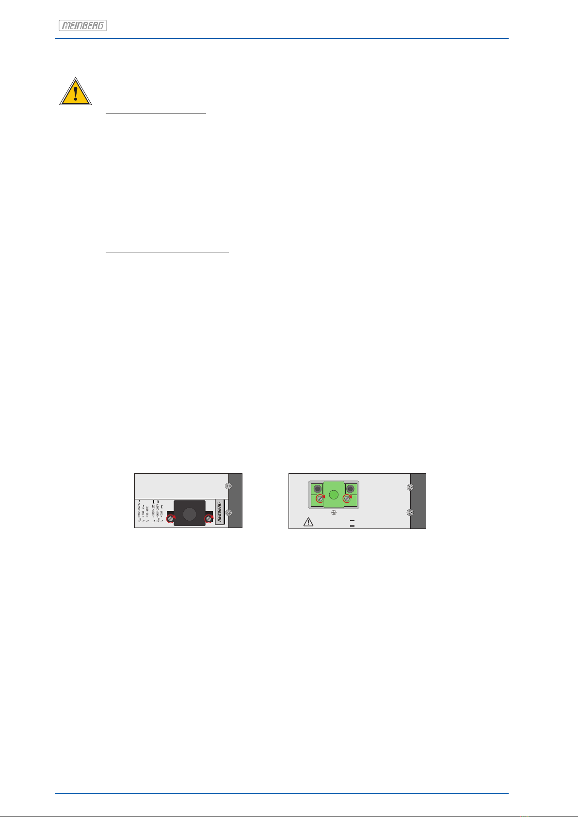
Ensure that all connections are secure—make sure that the lock screws of the power
supply plug are tightened when using a 3-pin MSTB or 5-pin MSTB connector (see diagram,
LANTIME M300 power supply).
-
+
U = 100 - 200 V
N
U = 90 - 250 V
max
5-Pin MSTB Connector 3-Pin MSTB Connector
Faulty shielding or cabling and improperly connected plugs are a health & safety risk (risk of
injury or death due to electrical shock) and may damage or even destroy your Meinberg device or
other equipment.
Ensure that all necessary safety precautions have been taken. Connect all cables to the device
only while the device is de-energized before turning on the power. Observe the safety instructions
on the device itself (see safety symbols).
The metal chassis of the device is grounded. When installing the device in an electrical enclosure,
it must be ensured that adequate clearance is provided, creepage distances to adjacent conductors
are maintained, and that there is no risk of short circuits.
In the event of a malfunction or if servicing is required (e.g., damage to the chassis or power cable,
ingress of fluids or foreign objects), the power supply may be cut off.
Please address any questions regarding your building’s electrical, cable or antenna installations
to the person or department responsible for that installation within your building.
6 Date: November 19, 2021 Converter

2 Important Safety Information
AC Power Supply
DC Power Supply
•The device is a Protection Class 1 device and
may only be connected to a grounded outlet
(TN system).
•For safe operation, the installation must be
protected by a fuse of a rating not exceeding
16 A and equipped with a residual-current
circuit breaker in accordance with applicable
national standards.
•The disconnection of the appliance from the
mains power supply must always be performed
from the mains socket and not from the
appliance itself.
•Mains-powered appliances are equipped with
a safety-tested mains cable designed for use
in the country of operation and may only be
connected to a grounded shockproof socket,
otherwise electric shock may occur.
•Make sure that the mains socket on the
appliance or the mains socket of the house
installation is readily accessible for the user
so that the mains cable can be pulled out of
the socket in an emergency.
•In accordance with IEC 62368-1, it must be
possible to disconnect the appliance from the
supply voltage from a point other than the
appliance itself (e.g., from the primary circuit
breaker).
•The power supply plug may only be fitted or
dismantled while the appliance is isolated
from the power supply (e.g., disconnected at
the primary circuit breaker).
•Supply cables must be adequately secured
and have an adequate wire gauge size.
Connection Cable Wire Gauge:
1 mm2–2.5 mm2
17 AWG –13 AWG
•The power supply of the device must have a
suitable disconnection mechanism such as a
switch. This disconnection mechanism must
be readily accessible in the vicinity of the
appliance and marked accordingly as a cut-
off mechanism for the appliance.
Converter Date: November 19, 2021 7

2.4 Fuse Replacement
WARNING!
This equipment is operated at a hazardous voltage.
Danger to life due to electrical shock!
- Disconnect the device from the mains! To do this, press the disconnector
(switch). Then, loosen the locking screws of the supply plug (if present)
and pull it off.
- Disconnect all signal lines such as, antenna, fault message relay contact
and serial interfaces from the device.
- Replace the fuse.
- Reconnect all cables in reverse order. If necessary, turn on the power again.
Example of fuse marking: T 2.5 A H 250 V
Trigger Characteristic:T (slow)
Nominal Current A: 2.5 Ampere
Switching Capacity: H (high)
max. Voltage: 250 V
AC Power Supply
DC Power Supply
Have the spare fuse ready, pay attention to the
correct rated current, characteristics and type.
Important: The fuse must be approved for
operation at (AC) voltage!
Have the spare fuse ready, pay attention to the correct
rated current, characteristics and type.
Important: The fuse must be approved for DC operation!
Fuse Type:
T Current A / Voltage V in accordance with IEC 60127
with or without extinguishing agent
T = Time-lag / SB = SlowBlow
Fuse Type:
T Current A / Voltage V in accordance with IEC 60127
with extinguishing agent
T = Time-lag / SB = SlowBlow
Dimensions:
5 x 20 mm
Dimensions:
5 x 20 mm
8 Date: November 19, 2021 Converter

2 Important Safety Information
2.5 Safety during Operation
WARNING!
Avoiding Short-Circuits
Protect the device against all ingress of solid objects or liquids. Ingress presents a risk of
electric shock or short-circuiting!
Ventilation Slots
Ensure that the ventilation slots are clean and uncovered at all times. Blocked ventilation slots
may cause heat to be trapped in the system, resulting in overheating. This may cause your device to
malfunction or fail.
Appropriate Usage
The device is only deemed to be appropriately used and EMC limits (electriomagnetic compatibility)
are only deemed to be observed if the chassis cover is properly fitted (thus ensuring that the device
is properly cooled, fire-safe, and shielded against electrical, magnetic and electromagnetic fields).
Switching the Device Off in the Event of a Malfunction or when Repairs are Required
It is not sufficient to simply switch off the device itself in order to disconnect the power supply.
If the device is malfunctioning, or if repairs become necessary, the device must be isolated from all
power supplies immediately.
To do so, follow the procedure below:
- Switch off the device from the unit itself.
- Pull out all power supply plugs.
- Inform the person or department responsible for your electrical installation.
- If your device is connected to an Uninterruptible Power Supply (UPS), it will remain
operational even after pulling the UPS power cable from the mains socket. In this case, you
will need to shut down your UPS in accordance with the user documentation of your UPS system.
Converter Date: November 19, 2021 9

2.6 Safety during Maintenance
WARNING!
When you are expanding the device, use only device parts that are approved for the system.
Non-observance may result in injury to the EMC or safety standards and cause malfunction
of the device.
If device parts, which are released for the system, are extended or removed there may be a
risk of injury in the area of the hands, due to the pull-out forces (approx. 60 N).
The service informs you which device parts may be installed.
The device must not be opened, repairs to the device may only be carried out by the
manufacturer or by authorized personnel. Improper repairs can result in considerable
danger to the user (electric shock, fire hazard).
Unauthorized opening of the device or of individual parts of the device can also lead to
considerable risks for the user and result in a loss of warranty as well as an exclusion
of liability.
- Danger due to moving parts - keep away from moving parts.
- Device parts can become very hot during operation. Do not touch these surfaces!
If necessary, switch off the unit before installing or removing any equipment,
and allow it to cool down.
2.7 Cleaning and Care
ATTENTION!
Never clean the device using liquids! Water ingress is a significant safety risk for
the user (e.g., electric shock).
Liquids can cause irreparable damage to the electronics of the device! The ingress of
liquids into the device chassis may cause short circuits in the electronic circuitry.
Only clean with a soft, dry cloth. Never use solvents or cleaners.
10 Date: November 19, 2021 Converter

2 Important Safety Information
2.8 Prevention of ESD Damage
ATTENTION!
An ESDS device (electrostatic discharge-sensitive device) is any device at risk of damage or
malfunction due to electrostatic discharges (ESD) and thus requires special measures to prevent
such damage or malfunction. Systems and modules with ESDS devices usually bear the following
symbol:
Symbol Indicating Devices with ESDS Components
The following measures will help to protect ESDS components from damage and malfunction.
When preparing to dismantle or install devices:
Ground your body (for example, by touching a grounded object) before touching sensitive devices.
Ensure that you wear a grounding strap on your wrist when handling such devices. These straps must
in turn be attached to an uncoated, non-conductive metal part of the system.
Use only tools and devices that are free of static electricity.
When transporting devices:
Devices must only be touched or held by the edges. Never touch any pins or conductors on the device.
When dismantling or installing devices:
Avoid coming into contact with persons who are not grounded. Such contact may compromise your
connection with the earth conductor and thus also compromise the device’s protection from any
static charges you may be carrying.
When storing devices:
Always store devices in ESD-proof ("antistatic") bags. These bags must not be damaged in any way.
ESD-proof bags that are crumpled or have holes cannot provide effective protection against
electrostatic discharges.
ESD-proof bags must have a sufficient electrical resistance and must not be made of conductive
metals if the device has a lithium battery fitted on it.
Converter Date: November 19, 2021 11

2.9 Return of Electrical and Electronic Equipment
ATTENTION!
WEEE Directive on Waste Electrical and Electronic Equipment 2012/19/EU
(WEEE Waste Electrical and Electronic Equipment)
Waste Separation
Product Category: According to the device types listed in Annex I of the WEEE Directive,
this product is classified as "IT and Telecommunications Equipment".
This product satisfies the labeling requirements of the WEEE Directive. The product symbol on
the left indicates that this electronic product must not be disposed of in domestic waste.
Return and Collection Systems
When disposing of your old equipment, please use the national return or collection systems
available to you. Alternatively, you may contact Meinberg, who will provide further assistance.
The return of electronic waste may not be accepted if the device is soiled or contaminated in
such a way that it potentially presents a risk to human health or safety.
Return of Used Batteries
The EU Battery Directive prohibits the disposal of batteries marked with the WEEE trashcan
symbol above in household waste.
12 Date: November 19, 2021 Converter

3 System CON/FO/TTL-4/DHS
The module is composed of a LWL card and a power supply, mounted in a housing for DIN mounting rail ready
for operation. The serial interface and the input/output signals of the system are accessible via connectors in
the front panel. The single modules are described below.
Converter Date: November 19, 2021 13

4 Attachment: Technical Information
4.1 Technical Specifications CON/DHS
Housing: Chassis for mounting on DIN rail
84mmx105mmx104mm(WxHxD)
Power Supply: 20-60 V DC
Power Consumption: max. 10 W
Ambient Temperature: 0...50 ◦C
Humidity: 85 %
Protection Class: IP20
4.2 Front Panel Connectors
Name Type Signal Cable / connection
———————————————————————————————————————————–
Power supply 3pin DFK male 20-60 V DC 3pin MSTB clamp
FO In ST-connector 850 nm FO input GI 50/125 µm or
GI 62.5/125 µm
TTL Out BNC female 2.5 Vpp into 50 Ohm shielded data line
14 Date: November 19, 2021 Converter

4 Attachment: Technical Information
4.3 DC Power Supply
Connection Type: 3-pin DFK
Pinbelegung: 1: +
2: PE (Potential Earth)
3: -
Input Parameter
——————————————————————————–
Nominal Voltage Range: UN= 48 V
Max. Voltage Range: Umax = 20-60 V
Nominal Current: IN= 0.17 A
Output Parameter
——————————————————————————–
Max. Power: Pmax = 8.0 W
Max. thermal energy: BTU = 27.30 BTU/h
Power
-
+
3
21
+
-
U = 20-60 V
max
U = 48 V
N
4.4 Fuse
The fuse protects against overload or short circuits and
thus prevents damage to the installed
power supply. The fuse is accessible from the front
panel and can be replaced.
Technical Specification
————————————————————
Rated Voltage: 250 V
Shutter delay: slow blow
Rated Current: 500 mA
————————————————————
Converter Date: November 19, 2021 15

4.5 Fiber Optic Input
Optical input: 850 nm Fiber optic input
Sensitivity 3µW min. (-25 dBm)
Connector: ST-conncector
Cable: GI50/125 µm or GI62.5/125 µm
gradient fibre
Fiber Optic
In
4.6 TTL Output
Output Signal: TTL
Level: 2.5 Vpp into 50 Ohm
Connection type: BNC, female
Cable: shielded coax line
TTL Out
16 Date: November 19, 2021 Converter
Table of contents
Other Meinberg Media Converter manuals

Meinberg
Meinberg TCR511 User manual

Meinberg
Meinberg CON/TTL/FO User manual

Meinberg
Meinberg SyncBox/N2X User manual

Meinberg
Meinberg microSync HR311/DC Use and care manual

Meinberg
Meinberg HR102/DC Use and care manual

Meinberg
Meinberg XHE-Rubidium User manual

Meinberg
Meinberg GPSGEN1575/MP User manual

Meinberg
Meinberg FO Use and care manual

Meinberg
Meinberg GPSGEN1575/MP User manual

Meinberg
Meinberg microSync HR100/DC Use and care manual