Meinberg IMS-M1000 User manual

MANUAL
IMS-M1000
Modular Sync. System and
NTP Server
9th June 2016
Meinberg Radio Clocks GmbH & Co. KG


Front view (Frontansicht) IMS-M1000
LANTIME M1000
Ref. Time
Time Service
Network
Alarm Terminal USB
Intelligent Modular Synchronization
1
DEUTSCH
1. LANTIME Bedienfeldanzeige mit LC-Display, Status LEDs und
Funktionstasten
2. Terminal / VT100, 38400 Baud, 8N1, 9pol. D-SUB Stecker
3. USB Anschluss
ENGLISCH
1. LANTIME control panel with LC-Display, Status LEDs
and function keys
2. Terminal / VT100, 38400 Baud, 8N1, 9pin D-SUB connector
3. USB connector
2 3

Rear view (Rückansicht) IMS-M1000
DEUTSCH
1. Netzteil: 100 - 240 V AC (50-60Hz) / 100 - 240 V DC oder
Netzteil: 20 - 72 V DC
2. GNSS Zeitcode Empfänger (GPS / GLONASS)
3. LAN-CPU mit USB Schnittstelle, LAN 0 - RJ45 Buchse
4. ACM - Active Cooling Module
ENGLISCH
1. Power Supply: 100 - 240 V AC (50-60Hz) / 100 - 240 V DC or
Power Supply: 20 - 72 V DC
2. GNSS timecode receiver (GPS / GLONASS)
3. LAN-CPU with USB interface, LAN 0 - RJ45 jack
4. ACM - Active Cooling Module
ACM
GPS 180
Antenna
Init
Nav Solved
Ant Fail
Fail COM
234
CPU C05F1
R T N A
0
CONSOLE
38400 / 8N1
1
Fan

Table of Contents
1 Imprint 1
2 Safety instructions for building-in equipment 2
2.1 AdditionalSafetyHints ........................................... 3
2.2 SupplyVoltage ................................................ 3
2.3 Cabling..................................................... 4
2.4 SafetyHintsAntenna ............................................ 4
2.5 ReplacingtheLithiumBattery ....................................... 5
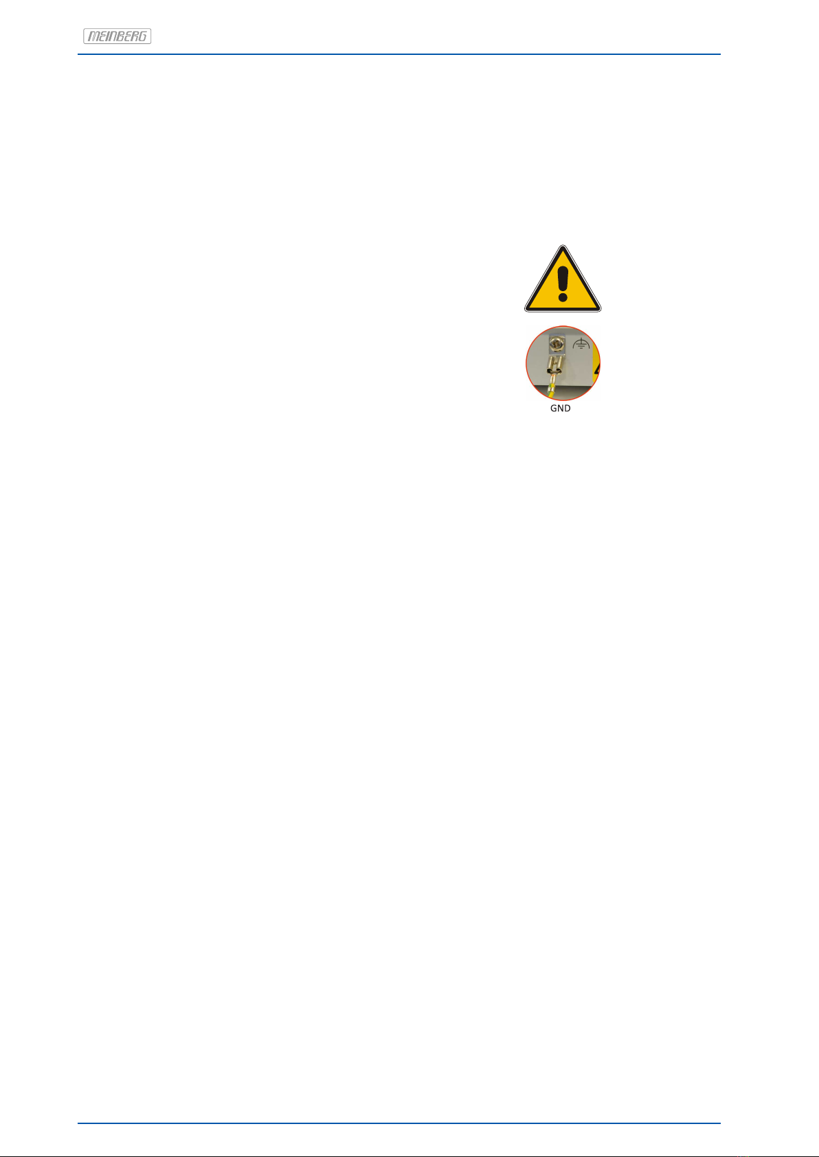
2.6 GroundingconnectionM1000........................................ 5
3 Quick Start 6
4 The Modular System LANTIME 7
5 Network Timeserver with GPS synchronized time base 8
6 Mounting the GPS Antenna 9
6.1 Example:.................................................... 9
6.2 Antenna Assembly with Surge Voltage Protection . . . . . . . . . . . . . . . . . . . . . . . . . . . . 10
6.3 AntennaShort-Circuit ............................................ 11
7 Booting the GPS180 receiver 12
8 Booting the Single Board Computer 13
9 Configuration User Interface 14
10 The Menues in Detail 15
10.1RootMenu................................................... 15
11 The graphical user interfaces 17
12 The WEB Interface 18
13 Attachment: Technical Information 19
13.1TechnicalSpecificationsM1000 ...................................... 19
13.2ACM-ActiveCoolingModule ....................................... 19
13.3 Available Modules and Connectors . . . . . . . . . . . . . . . . . . . . . . . . . . . . . . . . . . . . 20
13.4TERMINAL(Console) ............................................ 21
13.5USBConnector................................................ 21
13.6IMSModuleOptions............................................. 22
13.6.1 IMSM1000SlotAssignment ................................... 22
13.6.2 Power Supply 100-240 V AC/DC . . . . . . . . . . . . . . . . . . . . . . . . . . . . . . . . . 23
13.6.3 PowerSupply20-72VDC..................................... 24
13.6.4 GPSClock .............................................. 25
13.6.5 GLNClock .............................................. 26
13.6.6 RSCSwitchCard .......................................... 27
13.6.7 LAN-CPU............................................... 29
13.6.8 MRI - Standard Reference Input Signals . . . . . . . . . . . . . . . . . . . . . . . . . . . . 30
13.6.9 ESI - Telecom Synchronisation References . . . . . . . . . . . . . . . . . . . . . . . . . . . 31
13.6.10 LNE-GbE: Network Expansion with Gigabit Support . . . . . . . . . . . . . . . . . . . . . 32
13.6.11 HPS-100: PTP / SyncE / Hardware NTP Interface . . . . . . . . . . . . . . . . . . . . . . 33
13.6.12 TSU V3: IEEE-1588 Time Stamp Unit . . . . . . . . . . . . . . . . . . . . . . . . . . . . . . 35
13.6.13 CPE and BPE Output Modules (Frontend - Backend) . . . . . . . . . . . . . . . . . . . . . 36
13.6.14LIU-LineInterfaceUnit...................................... 41
0

13.6.15 LNO - 10MHz Sinus Output Module . . . . . . . . . . . . . . . . . . . . . . . . . . . . . . . 47
13.6.16 REL-1000: Error Relay Module . . . . . . . . . . . . . . . . . . . . . . . . . . . . . . . . . . 48
13.6.17 SCG - Studio Clock Generator . . . . . . . . . . . . . . . . . . . . . . . . . . . . . . . . . . 50
14 Declaration of Conformity 52
Date: 9th June 2016 IMS-M1000

1 Imprint
1 Imprint
Meinberg Funkuhren GmbH & Co. KG
Lange Wand 9, 31812 Bad Pyrmont - Germany
Phone: + 49 (0) 52 81 / 93 09 - 0
Fax: + 49 (0) 52 81 / 93 09 - 30
Internet:http://www.meinberg.de
Mail: [email protected]
Date: 2015-06-04
IMS-M1000 Date: 9th June 2016 1

2 Safety instructions for building-in equipment
This building-in equipment has been designed and
tested in accordance with the requirements of Stan-
dard IEC60950-1 "Safety of Information Technology
Equipment, including Electrical Business Equipment".
During installation of the building-in equipment in
an end application (i.e. rack) additional requirements
in accordance with Standard IEC60950-1 have to be
taken into account.
NOTE: First attach the case to protective earth -
before you connect the M1000 with the power line
(see chapter Grounding connection M1000).
General Safety instructions
•The building-in equipment has been evaluated for use in office environment (pollution degree 2) and
may be only used in this environment. For use in rooms with a higher pollution degree more stringent
requirements are applicable.
•The equipment/building-in equipment was evaluated for use in a maximum ambient temperature of 40◦C.
•The building-in equipment may not be opened.
•Protection against fire must be assured in the end application.
•The ventilation opening may not be covered.
For AC Supply 100-240 V AC
•The building-in equipment is a class 1 - equipment and must be connected to an earthed outlet
(TN Power System).
•For safe operation the building-in equipment must be protected by max 16 A fuse in the power installation
system.
•Disconnection of the equipment from mains is done by pulling the mains plug at the outlet. Don’t use the
connector at the module for disconnection from mains.
For DC Supply 100-240 V DC
•The device can be disconnected outside the unit in accordance with the regulations as in IEC 60950-1
(e.g. through primary side line protection).
•Assembling and disassembling of the power connector is only allowed if the device is disconnected from
power supply (e.g. trough primary side line protection).
•All feed lines are sufficiently protected and dimensioned.
Fuse: T2.5A
Connector Diameter: 1mm2- 2,5mm2/ 17AWG - 13AWG
2 Date: 9th June 2016 IMS-M1000

2 Safety instructions for building-in equipment
2.1 Additional Safety Hints
This manual contains important information for the installation and operation of this device as well as for your
safety. Make sure to read carefully before installing and commissioning the device.
Certain operating conditions may require the observance of additional safety regulations not covered by this
manual. Nonobservance of this manual will lead to a significant abatement of the security provided by this
device. Security of the facility where this product is integrated lies in the responsibility of the installer.
The device must be used only for purpose named in this manual, any other use especially opteration above the
limits specified in this document is considered as improper use.
Keep all documents provided with the device for later reference.
This manual is exclusively for qualified electricians or by a qualified electrician trained personnel who are
familiar with the applicable national standards and specifications, in particular for the construction of high
voltage devices.
2.2 Supply Voltage
WARNING!
This device is powered by a dangerous voltage. Nonobservance of the safety instructions of this manual may
lead to serious damage to persons and property and to danger to life! Installtion, commissioning, maintenance
and operation of this device are to be carried out by qualified personnel only.
The general safety instructions and standards ( e.g. IEC, DIN, VDE, EN ) for installation and work with
high voltage equipment as well as the respective national standards and laws must be observed.
NONOBSERVANCE MAY LEAD TO SERIOUS DAMAGE TO PERSONS AND PROPERTY AND TO DAN-
GER TO LIFE!
The device may not be opened. Repair services may only be carried out by the manufaturer.
Supply lines for this decice must be equipped via an appropriate switch that must be mounted close to the
device and must be marked as a mains switch for the device.
To ensure safe operation supply mains connected to this decice must be equipped with a fuse and a fault-
current circuit breaker according to the applicable national standards for safe operation.
The device must be connected to a protective earth with low grounding resistance according to the applicable
national rules.
IMS-M1000 Date: 9th June 2016 3

2.3 Cabling
WARNING!
DANGER TO LIFE BY ELECTRICAL SHOCK! NO LIVE WORKING!
Wiring or any other work done the connectors particularly when connectors are opened may never be carried out
when the installation is energized. All connectors must be covered to prevent from accidental contact to life parts.
ALWAYS ENSURE A PROPER INSTALLATION!
2.4 Safety Hints Antenna
WARNING!
DANGER TO LIFE BY ELECTRICAL SHOCK!
Make sure to comply with the occupational health and safety standards when installing the antenna. Never
work without a proper fall protection device!
Do not carry out any installation or maintenance work on the antenna system or cabling when there is a
potential risk of lightning.
Surge Voltage Protector
Due to extremely high currents associated with lightning no surge protection device can provide absolute safety
from the impacts caused by lightning!
4 Date: 9th June 2016 IMS-M1000

2 Safety instructions for building-in equipment
2.5 Replacing the Lithium Battery
Skilled/Service-Personnel only: Replacing the Lithium Battery
The life time of the lithium battery on the receiver boards is at least 10 years. If the need arises to replace the
battery, the following should be noted:
There is a Danger of explosion if the lithium battery is replaced incorrectly. Only identical batteries or
batteries recommended by the manufacturer must be used for replacement.
The waste battery has to be disposed as proposed by the manufacturer of the battery.
2.6 Grounding connection M1000
Note:
To ensure a safe operation and to fulfil the require-
ments in accordance with IEC 60950-1, the system must
be correctly connected to an equipotential grounding
bus. On the front panel of the system a grounding
connector is provided.
The mounting components (without a cable) are in-
cluded.
Tooth washer
Nut M4
Plain washer
Ring or
fork lug
Tooth washer
Nomel washer
Nomel washer
Flat connector
Tooth washer
Nut M4
Note:
Use a grounding cable with >= 1,5mm2
Please ensure a correct crimp connection!
IMS-M1000 Date: 9th June 2016 5

3 Quick Start
When booting the system the following message will be displayed while dots will be counted up in the lower line:.
Starting up
please wait ...
..........
Main Menu will be displayed with some important status informations after booting has finished:
NORMAL OPERATION
NTP: Offs. 2ms
Thu, 01.01.2008
UTC 12:00:00
If the GPS receiver remains asynchronous (Refclock LED is still red after 12 minutes) the number of satellites
in view and the good satellites are to check (press bottons ↓,→,↓from main menu). The antenna has to be
installed without any obstructions to the sky.
SV CONSTELLATION
SV in view: 10
Good Svs : 9
Sel:01 21 16 22
For first time installation enter TCP/IP address, netmask and default gateway. To get an overview of the
current configuration press F2 from main menu. Press F2 again to enter SETUP configuration page. Please
ask your administrator for propper TCP/IP configuration:
->Interfaces <-
Global Cfg.
Services
Use Up and Down
to select Port:
lan0:0 #1 of 1
>172.100.000.001
OK
Then press 3 times the OK button to change to IPV4 ETH0 configuration page to enter the IP address, netmask
and the default gateway:
NOTE: These settings are related to the first Ethernet connection (ETH0).
>IPv4 Parameter<
IPv6 Parameter
Link Mode
> ETH0 Address <
ETH0 Netmask
Def. Gateway
Set ETH0 Address
IPv4 ETH0
DHCP: enabled
172.000.000.000
OK OK
After this all further settings can be done via network interface, either by using a WEB browser or a Telnet
Session.
Default user: root
Default password: timeserver
6 Date: 9th June 2016 IMS-M1000

4 The Modular System LANTIME
LANTIME is a set of equipment composed of a reference clock GPS180, a single-board computer SBC ELX800
500 MHz with integrated network card, and a power supply unit, all installed in a metal desktop case and ready
to operate. The interfaces provided by LANTIME are accessible via connectors in the rear panel of the case.
Details of the components are described below.
The implemented NTPD distributes the reference time from the GPS180 receiver cyclic in the network. Infor-
mation on the NTPD is monitored on the LC-Display or can be inquired via the network.
The installation of LANTIME is very easy for the system/network administrator. The network address, the
netmask and the default gateway have to be configured from the front panel of LANTIME. The network address
or the equivalent name of LANTIME has to be shown to all NTP clients in the TCP/IP network.
As well as NTP the Linux system also supports a number of further network protocols: HTTP(S), FTP, SSH
and Telnet. Because of this remote configuration or status requests can come from any WEB browser. This
access via the network can be deactivated. Changes in the receiver status, errors or other important events are
logged either on the local Linux system or on an external SYSLOG-Server. In addition messages can be sent to
a data center via SNMP traps or automatically generated e-mails where they can be recorded. Furthermore all
alarm messages can be displayed by the large display VP100/20/NET that is accessed via network connection.
In order to avoid a service interruption several LANTIME NTP servers can be installed in the same network to
obtain redundancy.
IMS-M1000 Date: 9th June 2016 7

5 Network Timeserver with GPS synchronized
time base
The LANTIME (Local Area Network Time Server) provides a high precision time base to a TCP/IP network
(Stratum-1-Server). The NTP (Network Time Protocol) is used to synchronize all NTP clients with the refer-
ence. The several LANTIME variants differ from each other by the time reference and output configuration. A
GPS or combined GPS/GLONASS receiver, a long wave receiver (like DCF77, MSF or WWVB) or an IRIG time
code receiver can be integrated as an internal reference as well as a combination of these references (hybrid
system). External references are also possible.
The LANTIME system is a set of equipment composed of a internal receiver, a single-board computer and
a power supply, all installed in a metal 19 inch modular chassis and ready to operate. A simplified LINUX
operating system is installed on the single-board computers flash disk. Eight push buttons and a display can
be used to configure and monitor the time server.
After the network connection has been established the time server can also be configured and monitored
remotely from a workstation via TELNET or FTP. An integrated web server enables access to the LANTIME by
using an ordinary web browser.
8 Date: 9th June 2016 IMS-M1000

6 Mounting the GPS Antenna
The GPS satellites are not stationary, but circle round the globe with a period of about 12 hours. They can only
be received if no building is in the line-of-sight from the antenna to the satellite, so the antenna/downconverter
unit must be installed in a location that has as clear a view of the sky as possible. The best reception is
achieved when the antenna has a free view of 8◦angular elevation above the horizon. If this is not possible, the
antenna should be installed with the clearest free view to the equator, because the satellite orbits are located
between latitudes 55◦North and 55◦South. If this is not possible, you may experience difficulty receiving the
four satellites necessary to complete the receiver’s position solution.
The antenna/converter unit can be mounted on a wall, or on a pole up to 60 mm in diameter. A 50 cm
plastic tube, two wall-mount brackets, and clamps for pole mounting are included. A standard RG58 coaxial
cable should be used to connect the antenna/downconverter unit to the receiver. The maximum length of cable
between antenna and receiver depends on the attenuation factor of the coaxial cable.
Up to four GPS180 receivers can be run with one antenna/downconverter unit by using an optional antenna
splitter. The total length of an antenna line from antenna to receiver must not be longer than the max. length
shown in the table below. The position of the splitter in the antenna line does not matter.
The optional delivered MBG S-PRO protection kit can also be used for outdoor installation (degree of pro-
tection: IP55). However, we recommend an indoor installation, as short as possible after wall entering of the
antenna cable, to minimize the risk of overvoltage damage by lightning for example.
6.1 Example:
Type of cable diameter Ø Attenuation at 100MHz max lenght.
[mm] [dB]/100m [m]
RG58/CU 5mm 17 300 (1)
RG213 10.5mm 7 700 (1)
(1)This specifications are made for antenna/converter units produced after January, 2005
The values are typically ones; the exact ones are to find out from the data sheet of the used cable
IMS-M1000 Date: 9th June 2016 9

6.2 Antenna Assembly with Surge Voltage Protection
Optional a surge voltage protector for coaxial lines is available. The shield has to be connected to earth as
short as possible by using the included mounting bracket. Normally you connect the antenna converter directly
with the antenna cable to the system.
10 Date: 9th June 2016 IMS-M1000

6 Mounting the GPS Antenna
6.3 Antenna Short-Circuit
(systems with front display only)
In case of an antenna line short-circuit the following message appears in the display:
ANTENNA
SHORT-CIRCUIT
DISCONNECT POWER
! ! !
If this message appears the clock has to be disconnected from the mains and the defect eliminated. After that
the clock can be powered-up again. The antenna supply voltage must be 15VDC .
IMS-M1000 Date: 9th June 2016 11

7 Booting the GPS180 receiver
If both the antenna and the power supply have been connected, the system is ready to operate. About 2 minutes
after power-up the receiver’s oscillator has warmed up and operates with the required accuracy. If the receiver
finds valid almanac and ephemeris data in its battery buffered memory and the receiver’s position has not
changed significantly since its last operation, the receiver can determine which satellites are presently in view.
Only a single satellite must be received to synchronize and generate output pulses, so synchronization can be
achieved within one minute after power-up.
If the receiver position has changed by more than one hundred kilometers since last operation, the satel-
lites’ real elevation and Doppler might not match those values expected by the receiver, and this will force the
receiver to start scanning for satellites. This mode is called Warm Boot because the receiver can obtain ID
numbers of existing satellites from the valid almanac. When the receiver has found four satellites in view it can
update its new position and switch to Normal Operation. If the almanac has been lost (because the battery
has been disconnected) the receiver has to scan for a satellite and read in the current almanac. This mode is
called Cold Boot. It takes 12 minutes until the new almanac is complete and the system switches to Warm Boot
mode, scanning for other satellites.
12 Date: 9th June 2016 IMS-M1000

8 Booting the Single Board Computer
The LINUX operating system is loaded from a packed file on the flash disk of the single board computer to a
RAM disk. All files of the flash disk are stored in the RAM disk after booting. This guarantees that the file
system is in a defined condition after restart. This boot process takes approximately two minutes. During this
time the following message appears on the display:
NORMAL OPERATION
NTP: not sync
Thu, 01.01.2008
UTC 12:00:00
NORMAL OPERATION
NTP:sync to local
Thu, 01.01.2008
UTC 12:00:00
After starting the LINUX system, the network function is initiated and the communication program with the
receiver and the NTPD (NTP daemon) is started. Then NTPD starts synchronization with the reference clocks
(usually the hardware clock of the single board computer and the integrated receiver clock). The message "NTP:
sync to local" is displayed until synchronization is complete.
For the synchronization of the NTPD with the time reference it is necessary that the receiver is synchronous
with the incoming time signal. In this case the following message is monitored on the display:
NORMAL OPERATION
NTP: Offs. 2ms
Thu, 01.01.2008
UTC 12:00:00
The second line shows the user that the NTPD is synchronized with the receiver with an offset of 2ms (Figure).
Because of the internal time of the NTP which is adjusted by a software PLL (phase locked loop) it takes a
certain time to optimise this offset. The NTPD tries to keep the offset below +-128 ms; if the offset becomes
too large, the system time is set with the receiver’s time. Typically values for the offset are +-5 ms after the
NTPD has already synchronized.
IMS-M1000 Date: 9th June 2016 13

9 Configuration User Interface
There are several ways to configure the LANTIME parameters:
Command Line Interface (CLI) via TELNET
Command Line Interface via SSH
Command Line Interface via serial terminal in front panel
(38400/8N1/VT100)
HTTP Interface
Secure HTTP Interface (HTTPS)
Front panel LCD/VFD Interface (except LANTIME M100)
SNMP Management
In order to be able to configure the time server via the web interface or a telnet/SSH connection, an IP address
has to be assigned via the front panel keys and LC/VF display (for automatic assignment possibilities please
refer to: DHCP IPv4 or AUTOCONF IPv6). LANTIME variants without a display can be configured using the
serial terminal interface (labeled “Term” or “Terminal”) The termin program should be set to 38400Baud / 8N1
– VT100 emulation. Once the IPv4 address, net mask and IPv4 GATEWAY have been set up or the network
interface has been automatically configured with DHCP/Autoconf, further configuration changes can be done
via a network connection:
To set up a TELNET connection the following commands are entered (replace 198.168.10.10 with the IP of
your LANTIME):
telnet 198.168.10.10 // LANTIME IP address
user: root
password: timeserver
With “setup” the configuration program is started.
To set up a SSH connection the following commands are entered:
password: timeserver
With “setup” the configuration program is started.
To set up a HTTP connection the following address is to enter in a web browser:
http://198.168.10.10 // LANTIME IP address
password: timeserver
To set up a Secure HTTP (HTTPS) connection the following address is entered in a web browser:
https://198.168.10.10 // LANTIME IP address
password: timeserver
14 Date: 9th June 2016 IMS-M1000
Table of contents
Other Meinberg Other manuals
Popular Other manuals by other brands

Hubbell
Hubbell MMD21 Installation and maintenance instructions

EHEIM
EHEIM Proxima 175 operating instructions

Grizzly
Grizzly H7586 instruction sheet

Basler
Basler BE1-50 instruction manual

Feig Electronic
Feig Electronic OBID classic-pro ID CPR.02.VP/AB Series Installation

CEMO
CEMO Trolley 100 L AdBlue operating instructions