Sealey W1200T.V2 User manual

INSTRUCTIONS FOR
WHEEL REMOVAL TROLLEY 1200KG CAPACITY
MODEL NO: W1200T.V2
Thank you for purchasing a Sealey product. Manufactured to a high standard, this product will, if used according to these
instructions, and properly maintained, give you years of trouble free performance.
IMPORTANT: PLEASE READ THESE INSTRUCTIONS CAREFULLY. NOTE THE SAFE OPERATIONAL REQUIREMENTS, WARNINGS & CAUTIONS. USE
THE PRODUCT CORRECTLY AND WITH CARE FOR THE PURPOSE FOR WHICH IT IS INTENDED. FAILURE TO DO SO MAY CAUSE DAMAGE AND/OR
PERSONAL INJURY AND WILL INVALIDATE THE WARRANTY. KEEP THESE INSTRUCTIONS SAFE FOR FUTURE USE.
1. SAFETY
9At least two people are required to assemble the trolley.
9Ensure that the vehicle to be worked on is safely supported on axle stands.
9Ensure that the trolley is in sound condition and good working order before use.
9Keep trolley clean for best and safest performance.
9Onlyusethetrolleyonrm,level,unobstructedsurfacewhichiscapableofsupportingthetrolleyandwheel.
9Ensure there is no risk of pinching in between moving parts.
9Ensure work area has adequate lighting.
9Keep work area clean and tidy and free from unrelated materials.
9Keep children and unauthorised persons away from the work area.
9Ensure all non essential personnel keep a safe distance when the trolley is in use.
8DO NOT overload the trolley - maximum capacity is 1200kg.
8DO NOT allow untrained persons to operate the trolley.
8DO NOT allow anyone to ride on the trolley.
8DO NOT use on tarmacadam as it may sink under load.
9DO NOTdrivetheunitoveredges,roughsurfacesetc.whenloaded,asthewholeunitmayoverturn.
8DO NOT use trolley for purposes other than for which it is designed.
8DO NOToperatethetrolleywhenyouaretiredorundertheinuenceofalcohol,drugsorintoxicatingmedication.
8DO NOT make any alterations to this device.
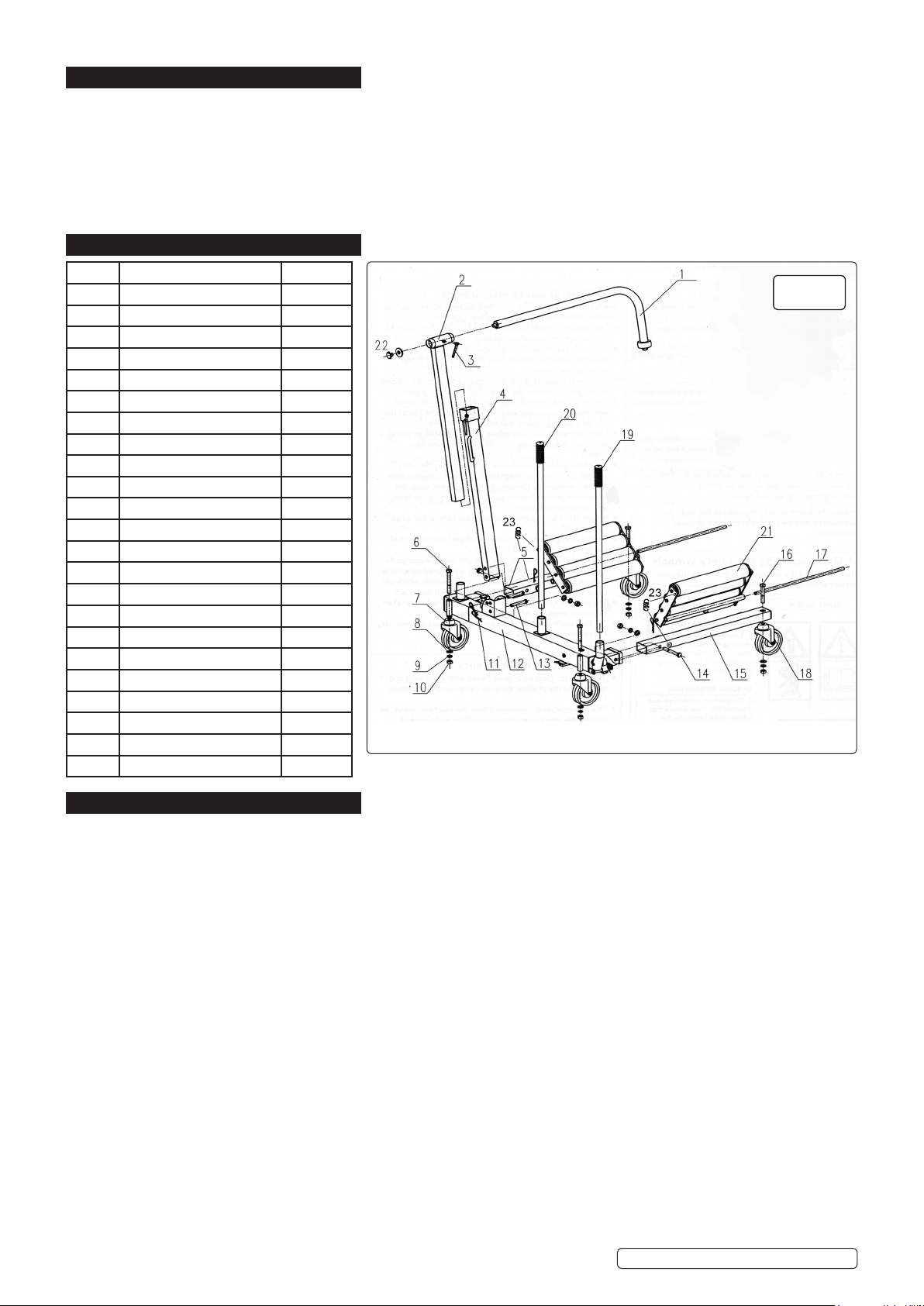
9AlwaysstandandoperatethewheeltrolleyfrombehindUprightTube(4),seeg.1.AlwaysmovetheWheelTrolleyusingoneHandle(20)
inthesocketonthelefthandside(asviewedintheg.1position)andtheotherHandle(19)intheSocketaboveLoweringPedal(A),see
g.2.
9Pushthewheelasfarontotherollersaspossible.
9Ensure that the load can not tilt whilst lowering or moving.
9Lower the wheel and secure it with the wheel support before transporting.
9It is of the greatest importance for safety that the wheel trolley is secured by the locking mechanism on the nearest hole before
manoeuvringtheunit.Ifthelockisnotused,thewheeltrolleycouldcomeapartwhilecarryingtheloadandthewheelcouldtipout.
9Maintaincorrectbalanceandfootingwhenmovingtrolleyandensurethattheoorisnotslippery.
9Wearsuitableclothingtoavoidsnagging.DO NOT wear loose jewellery and tie back long hair. A full range of personal safety equipment is
available from Sealey.
9Replace or repair damaged parts. Use only recommended parts. Unauthorised parts may be dangerous and will invalidate the warranty.
9Use a competent person to lubricate and maintain the trolley. DO NOTusebrakeuidtotopuphydraulicunit.Useapprovedhydraulicoil
only.
9Whennotinusestoretrolley,fullylowered,inasafe,dry,childproofarea.
WARNING!Failuretocomplywiththeseinstructionsmayresultinlossofload,damagetotrolleyorotherpropertyand/orpersonalinjury.
2. INTRODUCTION
Eight adjustable rollers (4 each side) allow for easy turning of large deep tread tyres. Extra large jacking handle and hydraulic foot pedal allows
for one man operation. Safety bar with composite guard goes around wheel to ensure stability during transportation. Locking mechanism allows
rollerstobexedateightpre-setpositions.Mountedontwolockingcastersandtwonon-lockingforimprovedstabilityandeasymanoeuvrability.
Ideal for use on agricultural and commercial wheels and tyres.
BEFORE OPERATION
Beforeoperating,adjusting
orservicingthemachine,
it is important that each
operator carefully reads the
operating instructions.
DURING OPERATION
Always use the locking
mechanism which locks
the lifting rollers in position
before manoeuvring the
loaded wheel changer.
DURING OPERATION
Danger from unsecured
load. The operator must
ensure that wheels to be
carried by the machine are
correctly loaded and
supported in accordance
with the operating
instructions.
DURING OPERATION
Potentialslip/fallhazard.
Never stand or ride on the
wheel changer when
working with the machine.
W1200T.V2|Issue3(I)23/08/16
Original Language Version
© Jack Sealey Limited

3. SPECIFICATION
Model No:............................................................W1200T.V2
Maximum Lifting Capacity: ......................................... 1200kg
MinimumWheelØ:................................................... 1000mm
MaximumWheelØ:.................................................. 1800mm
Roller Length:............................................................. 490mm
MinimumLiftingHeight:.................................................. 0mm
MaximumLiftingHeight:............................................. 760mm
OverallSize(WxDxH): ..................1300 x 1015 x 1500mm
4. ASSEMBLY LIST
5. ASSEMBLY
5.1. Refertog.1.
5.2. Ensure that at least two people assemble the trolley.
5.3. Fitsupportframe(left)(5)toframe(12).UseboltM16x110mm(14),atwasher16mm(8),springwasher16mm(9)andnutM16
(10).
5.4. Fitsupporttube(right)(15)toframe(12).UseboltM16x110mm(14),atwasher16mm(8),springwasher16mm(9)andnut
M16(10).
Note: Support frames are not handed. Ensure warning symbols are upwards and visible on trolley.
5.5. Fitbrakedcastors(7)toframe(12).UseboltM16x130mm(6),atwasher16mm(8),springwasher16mm(9)andnutM16(10).
5.6. Fitunbrakedcastors(18)toendofsupportframe(left)(5)andsupportframe(right)(15).UseboltM16x100mm(16),atwasher
16mm(8),springwasher16mm(9)andnutM16(10).
5.7. Fitrollertables(21).Getonepersontoholdtablewhilstotherinsertsmountingbar(17)withRclipholeendgoinginrst.Secure
with R clips (11).
5.8. Fit roller table tension springs (23). Insert top end of spring into hole on end of roller tables (21) and the other end of the spring into
nut welded onto the inner edges of support frame (right) (15) and support frame (left) (5).
5.9. Fit wheel support (4) to frame (12) with handle to rear. Use pin (13) and R clip (11). Ensure R clips are on outside of frame as
showning.1.
5.10. Insertclampsupportarm(1)intoslidingtube(2),(removehandwheelandwasher(22)rst),tightenclamp(3).Insertintowheel
support(4),tightenclamponwheelsupport(4).
5.11. Inserthandles(19and20)intosocketsshowning.1.
5.12.
5.13.
5.14.
5.15.
Part Description Quantity
1 Clamp support arm 1
2 Sliding tube 1
3 Adjustment clamp 2
4Wheel support 1
5 Support frame (left) 1
6BoltM16x130mm 2
7 Braked castor 2
8Flatwasher16mm 6
9Springwasher16mm 6
10 NutM16 6
11 Rclip 4
12 Frame 1
13 Pin 2
14 BoltM16x110mm 2
15 Support frame (right) 1
16 BoltM16x100mm 2
17 Mounting bar 2
18 Castor 2
19 Handle 1
20 Handle 1
21 Roller table 2
22 Handwheel + washer 1
23 Spring 2
Fig.1
W1200T.V2|Issue3(I)23/08/16
Original Language Version
© Jack Sealey Limited

6. OPERATION
6.1. USING THE WHEEL CHANGER TO REMOVE A WHEELRefertog.2
6.1.1. Positionthevehicleonasuitablehorizontaloorandapplythebrake.
6.1.2. Jackuptheaxleofthewheeltobechangedwithasuitablejack,sothatitisclearoftheoor.Securewithaxlestands.
6.1.3. Pressdowntheloweringpedal(A).
6.1.4. Pumpthewheelchangerapartwiththepumplever(C).
6.1.5. Adjust the wheel support (D) so that the clamp support arm (E) is positioned over the wheel to be handled.
6.1.6. Pushthewheelchangerunitunderthewheelsothattherollertablesarepositionedeithersideofthewheelandthatthewheelsits
up against wheel support (D).
6.1.7. Checkthattheloweringpedal(A)isinitsuppermostposition.Pumptheunittogetheruntilthewheelandtheunitcannotglide
apart.
6.1.8. Lower the clamp support arm (E) behind the wheel and adjust until the wheel is vertical and can be moved approximately 5cm
sideways. This will allow the wheel to be rotated in the wheel changer when relocating wheel studs. Lock the clamp support arm in
position by tightening adjustment clamps (I and J).
Note: theangleofthewheelsupportscanbeadjustedbytheremovalofpin(H)toaccommodatedifferentwheelcongurations,
seeg.2.B.
WARNING! Wheel support (D) and clamp support arm (E) are only used to balance the wheel NOT to carry a load!
6.1.9. Liftthewheelbypumpingthelever(C).Whenthewheelispositionedontheunitthewheelchangermustbesecuredinthelifting
position with the locking mechanism (F).
▲IMPORTANT: Ensure that the locking mechanism (F) is secured through the nearest location hole on the inner member. This
prevents unintentional lowering of the wheel while it is being handled.
6.1.10. With the wheel nuts removed the wheel can now be safely carried away on the wheel changer.
6.1.11. Put pump lever (C) into socket (K). Use with handle (L) to push the wheel changer.
6.2. UNLOADING THE WHEEL CHANGER Refertog.2.
6.2.1. Whenthewheelislocatedonthewheelstudsandsecuredwiththewheelnutsorthewheelhasbeenmovedtoaplacefor
storage,thewheelcanbereleased.
6.2.2. Loosen clamp support (E) by releasing adjustment clamps (I and J).
6.2.3. Lift and release locking mechanism (F).
6.2.4. Pressdowntheloweringpedal(A).Pumpapartthewheelchangerwiththepumplever(C).
6.2.5. Adjust the wheel support arm (E) so that it does not catch on the top of the wheel before manoeuvring the wheel changer clear of
the wheel.
6.2.6.
6.2.7.
6.2.8.
6.2.9.
6.2.10.
6.2.11.
6.2.12.
6.2.13.
6.2.14.
6.2.15.
6.2.16.
6.2.17.
6.2.18.
6.2.19.
6.2.20.
6.2.21.
6.2.22.
6.2.23.
6.2.24.
6.2.25.
6.2.26.
6.2.27.
6.2.28.
6.2.29.
6.2.30.
6.2.31.
6.2.32.
Fig.2
W1200T.V2|Issue3(I)23/08/16
Original Language Version
© Jack Sealey Limited

NOTE: It is our policy to continually improve products and as such we reserve the right to alter data, specications and component parts without prior notice.
IMPORTANT: No liability is accepted for incorrect use of this product.
WARRANTY:Guaranteeis12monthsfrompurchasedate,proofofwhichwillberequiredforanyclaim.
SoleUKDistributor,SealeyGroup.
KempsonWay,SuffolkBusinessPark,
BurySt.Edmunds,Suffolk.
IP327AR
www.sealey.co.uk
sales@sealey.co.uk
01284757500
01284703534
Web
Environmental Protection
Recycle unwanted materials instead of disposing of them as waste. All tools, accessories and packaging should be
sorted, taken to a recycling centre and disposed of in a manner which is compatible with the environment.
When the product becomes completely unserviceable and requires disposal, drain off any fluids (if applicable)
into approved containers and dispose of the product and the fluids according to local regulations.
7. MAINTENANCE
7.1. Daily:Checkfordamageanduidleaks.
7.2. Every 8 working hours: Check hydraulic oil level. Ensure that the trolley is pumped apart guarantee to its widest possible
position.Removetheoilreservoirllerplug,g.2.G,andchecktheoillevel.Topupasnecessaryusingapprovedhydraulicoilonly.
Correctoillevelshouldbeatthebottomofthethreadsoftheoilreservoirllerplugaperture.
(Sealeypartno.HJO500MLS/HJO5LS).
7.3. Monthly: Lubricate moving parts and check for abnormal wear and tear.
▲IMPORTANT:NO RESPONSIBILITY IS ACCEPTED FOR INCORRECT USE OF THIS PRODUCT.
Hydraulicproductsareonlyrepairedbylocalserviceagents.Wehaveservice/repairagentsinallpartsoftheUK.
DO NOT return the trolley to us. Pleasetelephoneuson01284757500toobtaintheaddressandphonenumberofyourlocal
agent. If the trolley is under guarantee contact your local Sealey dealer.
8. TROUBLESHOOTING
8.1. Rollertableswillnotextendtotheirfullwidth-lowhydrauliclevel.Checkandllseesection7.1.
8.2. Pumpleverineffective-hydraulicoilleveltoohigh.Checkanddrainseesection7.1.
W1200T.V2|Issue3(I)23/08/16
Original Language Version
© Jack Sealey Limited
Table of contents
Other Sealey Other manuals
Popular Other manuals by other brands

HydraMaster
HydraMaster TITAN 425 Owner’s Guide and Maintenance Schedule

Zaya.co
Zaya.co Skimmer Overflow Stopper 800 user manual

Lascal
Lascal KIDDYGUARD owner's manual

Nady Audio
Nady Audio MPM 8175 owner's manual

iLive
iLive ISP591B user guide

Concept Z Performance
Concept Z Performance 350Z installation guide