Meistergram M'100-JNS User manual
M'100-JNS and M'SO-JNS MONOGRAM MACHINES
AND PARTS BOOK
ORDERS FOR PARTS OR INQUIRIES FOR SERVICE
SHOULD
BE DIRECTED TO THE
CLEVELAND
OFFICE
Main
Office
and
Plant
5501
Cass
Ave.
Cleveland,
OH
441
02
(216)
281-5450
New
York
Showroom
14
East
38th
St.
New
York,
NY
10016
(212)
685-0888
Los Angeles, Showroom
3303
Harbor
Blvd.,
#E-8
Costa
Mesa,
CA
92626
(714)
241-8033
monogram and embroidery systems
© MEISTERGRAM, INC.
1978
From the library of: Superior Sewing Machine & Supply LLC
TABLE
OF
CONTENTS
Section I
M'1 00-JNS Machine Complete
....................................
.
M'100-JNS and M'80-JNS
Machine
Head
...........................
.
Threading
Machine
and Needles
..................................
.
Bobbin
Winder
Assembly and
Adjustment
..........................
.
Thread Types,
Adjusting
Upper
Thread Tension,
Tension Take-up
Spring
.......................................
.
Bobbin
Case Threading and
Adjustment
............................
.
Stitch
Width Control and
Adjustment
...............................
.
Presser Foot Assembly and
Adjustment
............................
.
Motor
and Clutch Assembly
......................................
.
Cleaning and Oiling
Machine
Head
................................
.
Timing
the
Hook
and Needle
......................................
.
Adjusting
Zigzag Mechanism
.....................................
.
M'100-JNS Pantograph Parts:
Hoop Arm Assembly
..........................................
.
Upper Pantograph Assembly
...................................
.
Lower Pantograph Assembly
...................................
.
Page No.
1
2
3
4
5
6
7
8
9
10
11
12
13
14
14
Template
Holder
Assembly . . . . . . . . . . . . . . . . . . . . . . . . . . . . . . . . . . . . . . 14
Pantograph
Instruction
. . . . . . . . . . . . . . . . . . . . . . . . . . . . . . .
15,
16, 17 &
18
Section II (see
front
page
of
this section
for
contents)
Instructions
as to
monogramming
and
basic
operation
of
equipment,
working
with
different
types
of
material and garments, cause and
correction
of
common
operating
problems.
Section Ill (see
front
page
of
this
section
for
contents)
Detailed parts listing
for
internal
components
of
the M'80-JNS and M'100-JNS
monogram machine head.
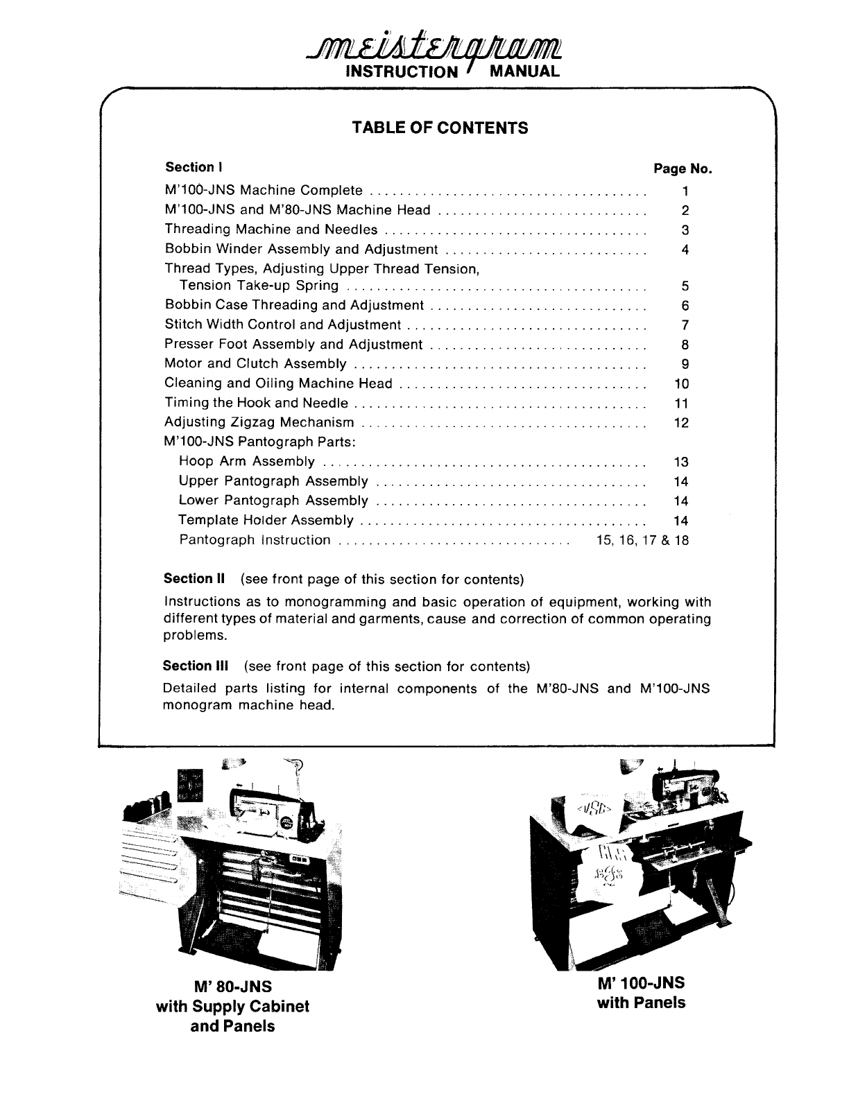
M' 80-JNS
with Supply Cabinet
and Panels
M' 100-JNS
with Panels
From the library of: Superior Sewing Machine & Supply LLC
eJ
~~~v
(:
~
~
\
1AV
~v
~·v
~V~'IfA~
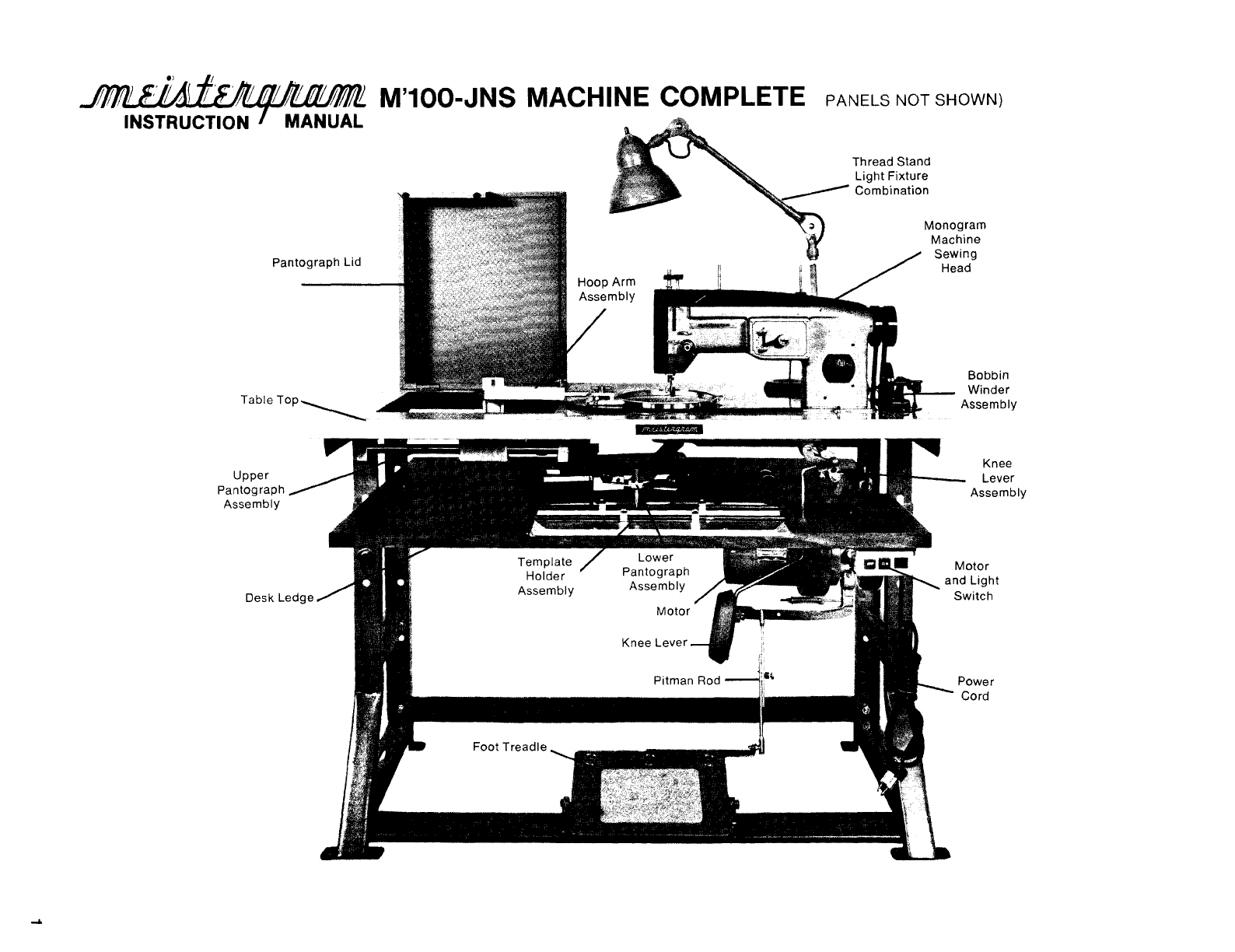
M'100-JNS MACHINE COMPLETE
PANELs
NOT
sHowN)
INSTRUCTION MANUAL
Pantograph Lid
Upper
Pantograph
Assembly
Thread Stand
Light
Fixture
Combination
Monogram
Machine
Sewing
Head
Bobbin
Winder
Assembly
Knee
Lever
Assembly
Motor
and Light
Switch
From the library of: Superior Sewing Machine & Supply LLC
l!~Y
~)I
(
·~~
11
~~~
?~~'!J~~
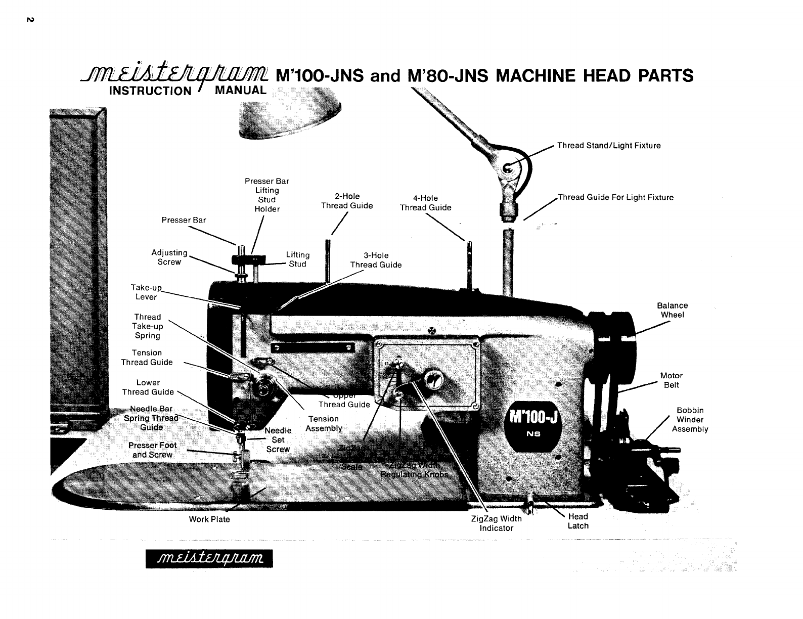
M'100-JNS and M'80-JNS MACHINE HEAD
PARTS
INSTRUCTION
Presser Bar
Tension
Thread Guide
~
2-Hole
Thread Guide
I 4-Hole
Thread Guide
~
Thread
Stand/Light
Fixture
/Thread
Guide For Light Fixture
Bobbin
Winder
Assembly
From the library of: Superior Sewing Machine & Supply LLC

6. Up to and
through
thread take-up lever.
7. Down
through
tension
thread
guide.
8.
Through
lower
thread
guide.
NEEDLES
Scarf
'],
_l~l~
(
,'
~
/)
,;',/
'/!
/V
~,V
~VJ0f~
~NSTRUCTION
MANUAL
THREADING MACHINE
2.
Through
three-holed
thread
guide
starting
with
top
hole
.c1nd
working
down,
back
to
front.
1.
Bring
thread from the
:hread
cone
up
through
thread
:;uide
located
on lamo stand.
~hen
through
the
4-hole
thread
guide
pm
located
on top
of
head, then
through
the
2-hole
:hread gu1de.
3.
Draw
thread
down
the
front
of the
machine
around
and
under
from
right
to
left
between
the
tension
discs.
5.
Under
tension
thread
guide
and
through
upper
thread
guide.
NEEDLES
It is very
important
that
the
proper
type
needle
be
used
with
your
M'80-JNS
or
M'1 00-JNS
machine.
These
needles
are
readily
available
from
Meistergram
in the
following
sizes: (The
numbers
in
parentheses
are
the
metric
equivalent)
#7 (60),
#9
(65),
#1
0 (70),
#11
(75), #12 (80}, #14 (90).
The size
of
the
needle
is
stamped
on the
shank
of
each
needle.
Sizes 10
or
11
will
work
well on
almost
all types and
thicknesses
of
material.
For
thin
or
sheer
material
a size 7
or
9 may
provide
better
results:
for
very
thick
material
a
size 12
or
14 may be required. However, when
switching
to
these
extreme
size
needles it may be
necessary
to
re-time the machine. (see
section
on
Timing)
Inserting Needle
1) Turn
balance
wheel
forward
until
needle
bar
is at
it's
highest
point. Loosen
screw
on needle
bar
and
insert
needle as
far
up
as
it
will
go.
2)
Be
sure
needle
eye and
long
groove
are
facing
forward
toward
operator.
The
scarf
should
be
facing
toward
the back.
3) Be
sure
needle
is
not
bent,
blunt
or
rough. Do
not
use
needle
size
any
larger
than
necessary
for
the
material
being
monogrammed.
3
From the library of: Superior Sewing Machine & Supply LLC
4
17.~/
,~~
/V
~r;
r;.Vr;l!J~~
INSTRUCTION MANUAL
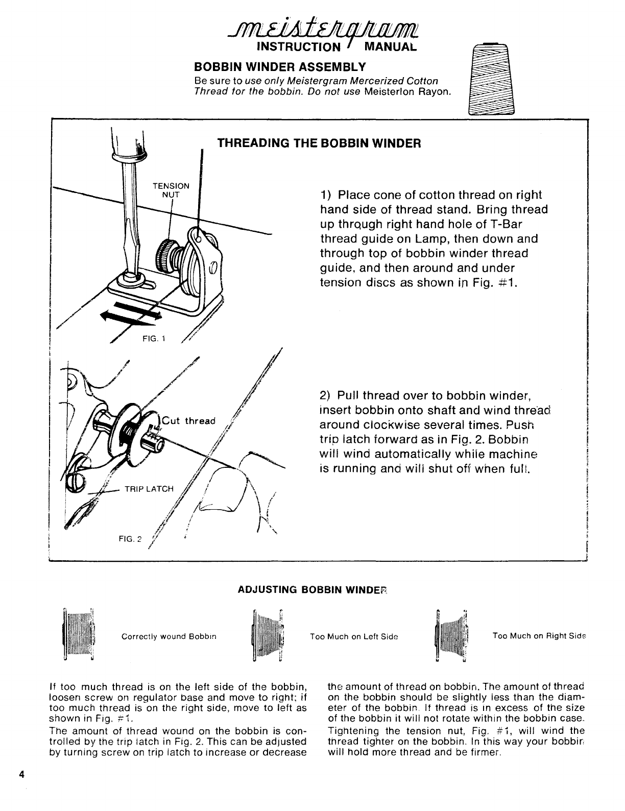
BOBBIN WINDER ASSEMBLY
Be
sure
to
use
only
Meistergram
Mercerized
Cotton
Thread
tor
the
bobbin.
Do
not
use
Meisterlon
Rayon.
THREADING THE BOBBIN WINDER
1) Place cone
of
cotton
thread on right
hand side
of
thread stand. Bring thread
up
thrqugh right hand hole
ofT-Bar
thread
guide
on Lamp, then down and
through
top
of
bobbin
winder
thread
guide. and then around and
under
tension discs as shown in Fig.
#1.
2) Pull thread
over
to
bobbin
winder,
insert
bobbin
onto
shaft and
wind
thre·ad
around
clockwise
several times. Push
trip
latch
forward
as in Fig.
2.
Bobbin
will
wind
automatically
while
machine
is running and
will
shut
off
when fulL
ADJUSTING BOBBIN WINDER
Correctly
wound
Bobbm
If
too
much
thread
is on
the
left
side
of
the
bobbin,
loosen
screw
on
regulator
base and
move
to
right;
if
too
much
thread
is on
the
right
side,
move
to
left
as
shown
in Fig.
#1.
The
amount
of
thread
wound
on
the
bobbin
is
con-
trolled
by
the
trip
latch
in Fig.
2.
This
can
be
adjusted
by
turning
screw
on
trip
latch
to
increase
or
decrease
Too
Much
on
Left
Side
Too
Much
on
Right
Side
the
amount
of
thread
on
bobbin.
The
amount
of
thread
on the
bobbin
should
be
slightly
iess
than
the
diam-
eter
of
the
bobbin,
If
thread
is
rn
excess
of
the
size
of
the
bobbin
it
will
not
rotate
within
the
bobbin
case.
Tightening
the
tension
nut, Fig. #
1,
will
wind
the
thread
tighter
on
the
bobbin.
In
this
way
your
bobbin
will
hold
more
thread
and be firmer,
From the library of: Superior Sewing Machine & Supply LLC

THREAD
Meistergram
threads
are
orepared
exclusively
for
use
with
our
high
speed
monogram
machines
and are
color
fast. Refer
to
Thread
Color
Cards
for
selection
and
be
sure
to
specify
"Meistergram
Gatton"
or
"Meisterlon
Rayon"
when
ordering.
;·v1eisterion
Silk-like
Rayon
-
approx.
5,500 yds.
Too
Thread-
use
either
cotton
or
rayon.
Bobbin
Thread-
use
onlv
cotton.
Fer
finer
appearance
use same
color
cotton
thread
in
bobbin
to
match
the
top
thread
being
used.
;,1eisteraram
Mercerized
Cotton~
approx.
12,000 yds.
ADJUSTING UPPER THREAD TENSION:
Correct
Tension
)p
Too
Loose
or
""'ottom
Too
Tight
Top
Too
Tight
or
)ttom
Too
Loose
The
upper
thread
tension and
bobbin
tension
can be
set
independently
of
each
other
and are
very
important
for
producing
proper
stitch
(see
section
on
Bobbin
Tension
and Case).
Tensions
should
be
set
so
that
on
the
back
of
the
monogram,
the
bobbin
stitch
is
about
1f3
of
the
width
of
the
top
zigzag
stitch.
Tension on the
top
thread
can be
adjusted
by
turning
the
tension
nut (A) in Fig.
1.
Ten-
sion
may
be
adjusted
for
variances
in
thread
and
material
being
embroidered.
If tension is
too
tight
it
may cause
thread
breakage,
puck-
ering
of
material,
the
bobbin
will
be
too
wide
on the
back
or
the
bobbin
may
pull
up
and
show
through
the
top
of
the
material. If ten-
sion
is
too
loose,
thread
may
loop
on
top
or
bottom
of
material,
embroidery
will
not
lay
smoothly
and
very
little
bobbin
will
show
on
back
of
monogram.
To
check
tension,
thread
the
machine
through
the
tension
assembly
and
take-up
lever.
Then
pull
on
thread
by
hand
to
feel the
amount
of
tension
and
adjust
accordingly.
Take-up
lever
should
be
at
its
highest
posi-
tion
when
doing
this.
FIG. 1
Adjusting
Top
Tension
Nut
TENSION TAKE-UP SPRING
(often referred to as
check
spring
or
thread
controller
spring)
Extending
from
behind
the
tension
discs
is
a
hooked
spring
called
the
tension
take-up
spring.
This
spring
pro-
vides
tension
on the
top
thread
until
the
needle
has
carried
it
down
to the material. It
may
be
necessary
to
adjust
the
tension
of
the
take-up
to
lighter
tension
on
thinner
material
and
tighter
tension
on
thicker
material.
~~~~n
TAKE-UP
SPRING
/~-
I
1(1
\
I
Ill
/-;~
]
1
I/
//
~~
/LIGHTER
j j ' FIG. 2
Insert
screwdriver
into
tension
stud
and
turn
slightly
as
shown
in Fig.
2.
This
will
wind
the
spring
tighter
or
make
it
looser
and
you
can
determine
the
amount
of
spring
pressure
by
pushing
it
with
your
finger.
If
tension
is
too
loose,
thread
will
loop
up
under
material
or
on
top.
if
too
tight
it
may
cause
the
stitches
to
skip.
CHANGING THE TAKE-UP SPRING:
If the
take-up
spring
breaks
or
becomes
too
worn
to
operate
properly
then the
spring
should
be replaced. First,
loosen set
screw
in the head
located
to the
right
on the
tension
assembly
and remove the assembly.
5
From the library of: Superior Sewing Machine & Supply LLC

6
TENSION
ADJUSTING SCREW
BOBBIN CASE
BOBBIN CASE
Raise needle bar to highest position.
To
remove the
bobbin
case,
tilt
back
the
machine
head
or
reach
under
the
machine. Open latch on case and remove both the case and
bobbin.
When the latch is open, the
bobbin
will be held in the
case; when latch is released
bobbin
drops
out.
THREADING BOBBIN CASE:
I
1.
Place
bobbin
into
case as shown.
2.
Guide thread
into
slot
on
top
of case.
3.
Pull thread
under
tension spring
and
wind
around
pig-tail thread
guide.
5.
Replacing Bobbin Case:
4.
Tension on the
bobbin
case can be adjusted
by
turning
tension screw.
Tension should be set
so that
slight
amount
of
pull is required
to
release thread.
Raise needle
bar
to
highest
position,
hold
latch on
case open
to
retain the bobbin,
tilt
bacK
machine
head
or
reach underneath
with
bobbin
case and insert on
shaft in the hook assembly. Release latch and press
bobbin
case
into
position so that you hear a
distinct
"click".
If you
do
not
hear
click,
remove case and
insert again. Be sure
that
several inches
of
bobbin
thread are hanging free from
bobbin
case.
NOTE: Make sure
bobbin
case
is
free
of
dirt
and
oil. Use
only
cotton
thread
in the
bobbin.
Do
not
use rayon.
From the library of: Superior Sewing Machine & Supply LLC
I ,
~...,.~"'-"11~'~(
·~~
~~
~~
~~~~~~
INSTRUCTION MANUAL
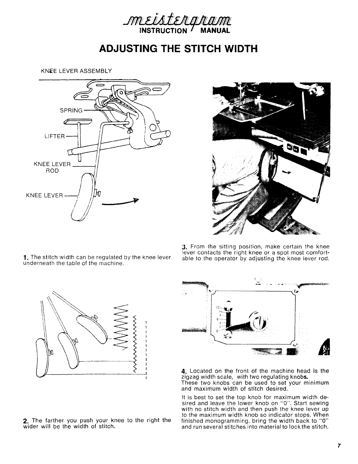
ADJUSTING THE STITCH WIDTH
KN~E
LEVER
ASSEMBLY
KNEE
LEVER
ROD
---~
1. The
stitch
width
can be regulated by the knee lever
underneath
the
table
of the machine.
3. From the
sitting
position,
make
certain the knee
lever
contacts
the
right
knee
or
a
spot
most
comfort-
able to the
operator
by
adjusting
the knee
lever
rod.
4.
Located
on the
front
of
the
machine
head is the
zigzag
width
scale, with
two
regulating
knobs.
These
two
knobs can be used to set
your
minimum
and
maximum
width
of
stitch
desired.
It is best to set the top knob
for
maximum
width
de-
sired and leave the
lower
knob on
"0".
Start
sewing
with no stitch
width
and then push the knee
lever
up
to the
maximum
width
knob so
indicator
stops. When
2.
The
farther
you push
your
knee
to
the
right
the finished
monogramming,
bring
the
width
back
to
"0"
wider
will
be the
width
of
stitch. and run several
stitches
into material to
lock
the
stitch.
7
From the library of: Superior Sewing Machine & Supply LLC

8
2~
Presser
Bar
Lifting---
Stud Holder
5.
Presser
Bar
Spring
6.
Guide Bracket
PRESSER FOOTASSEMBLY
ADJUSTING THE PRESSER FOOT
The
"jumping"
presser
foot
is an
exclu-
sive
design
found
only
on
Meistergram
monogram
machines. The
presser
foot
action
is
coordinated
with
the
move-
ment
of
the
needle
bar
so
that
the
foot
applies
pressure to the
material
during
stitching
and then releases
pressure
to
allow
movement
of
the material
after
the
needle
has
risen
clear
of
the
materiaL
To
adjust
the
presser
foot,
turn
the
balance
wheel
forward
so
that
the
needle
has
gone
into
the
material
and then has
just
come
out
of
the
material
on
the
upward
stroke.
At
this
point,
loosen
the
screw
holding
the
presser
toot
and posit1on
the
foot
so
that
it is
lightly
pressing
down
on the
material.
Tighten
the
screw.
The
presser
foot
should
be
adjusted
when
embroidering
different
thicknesses
of
material.
Oniy
slight
pressure
is
required
to
hold
the
material
as
the
needle
passes
up
through
it. If
too
much
pressure
is
used the
foot
will
bang
on the
work
plate.
The
foot
can
be raised
up
and
thus
disconnected
from
the
action
of
the
needle
movement
by
lifting
the
lever
on
the
back
of
the
head.
However,
you
should
not
operate
the
machine
with
the
foot
in
this
position
as
the
screw
on
the
needle
bar
may
hit
the
foot
and
bend
it. If you
wish to
operate
the
machine
with
the
presser
bar
up,
remove
the
presser
foot.
From the library of: Superior Sewing Machine & Supply LLC
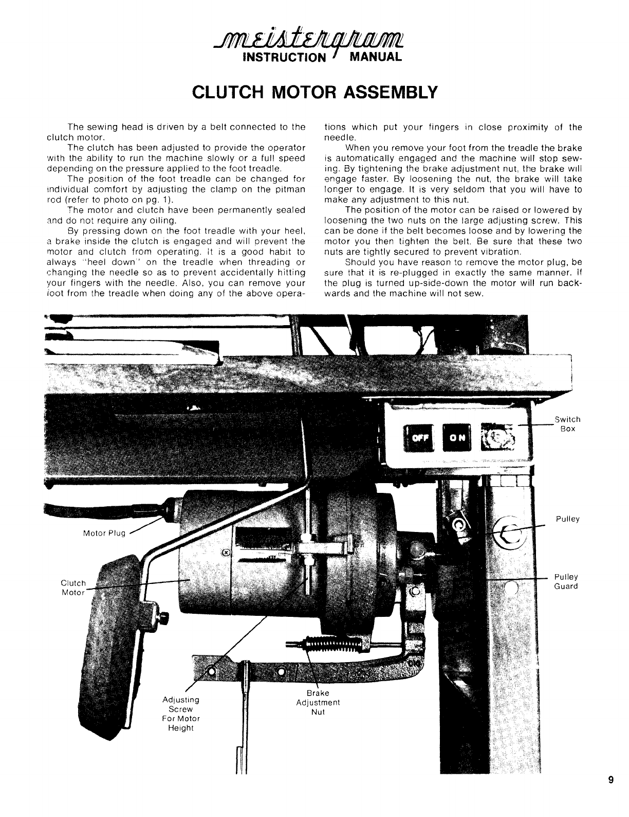
CLUTCH MOTOR ASSEMBLY
The
sewing
head is
driven
by a
belt
connected
to
the
clutch
motor.
The
clutch
has been
adjusted
to
provide
the
operator
with
the
ability
to run the
machine
slowly
or
a full
speed
depending
on
the
pressure
applied
to the
foot
treadle.
The
position
of
the
foot
treadle
can be
changed
for
mdividual
comfort
by
aajustiog
the
clamp
on
the
pitman
rod
(refer
to
photo
on pg. 1
).
The
motor
and
clutch
have been
permanently
sealed
and
do
not
require
any
oiling.
By
pressing
down
on the
foot
treadle
with
your
heel,
2
brake
inside
the
clutch
is
engaged
and
will
prevent
the
motor
and
clutch
from
operating.
It is a
good
habit
to
always
"heel
down"
on
the
treadle
when
threading
or
changing
the
needle
so as to
prevent
accidentally
hitting
your
fingers
with
the
needle.
Also, you can
remove
your
root
from
the
treadle
when
doing
any
of
the
above
opera-
tions
which
put
your
fingers
in
close
proximity
of
the
needle.
When you
remove
your
foot
from
the
treadle
the
brake
is
automatically
engaged
and
the
machine
will
stop
sew-
ing. By
tightening
the
brake
adjustment
nut,
the
brake
w11l
engage
faster. By
loosening
the
nut, the
brake
will
take
longer
to
engage.
It
is
very
seldom
that
you
will
have to
make
any
adjustment
to
this
nut.
The
position
of
the
motor
can be raised
or
lowered
by
loosening
the
two
nuts
on the
large
adjusting
screw.
This
can
be
done
if
the
belt
becomes
loose
and by
lowering
the
motor
you
then
tighten
the
belt. Be
sure
that
these
two
nuts
are
tightly
secured
to
prevent
vibration.
Should
you have reason
to
remove
the
motor
plug,
be
sure
that
it is
re-plugged
in
exactly
the same
manner.
lf
the
plug
is
turned
up-side-down
the
motor
will
run
back-
wards
and
the
machine
will
not
sew.
Pulley
Pulley
Guard
9
From the library of: Superior Sewing Machine & Supply LLC

10
CLEANING AND OILING
Like
any
other
piece
of
machinery
it
is very
important
to keep the head and ail moving parts cleaned and
lubricated.
located
under
the
top
cover
of
the machine are two
separate oil reservoirs. When you
first
receive
your
ma-
chine, remove the
top
cover
and then remove the
cover
plates
of
the reservoirs. Saturate the felt pads in each
reservoir
with
oil and replace the covers.
In
future
oilings
it
will
only
be necessary to fill the reservoirs by oiling
through
the
hole
in the
top
cover.
Located on the head you will find various
other
oil
holes. Oil holes are also located
under
the
work
plate. You
should
oil
each
of
these holes at least
twice
a week to keep
your
machine
running smoothly. If the machine is being
used
continuously
put a few
drops
of
oil in all oil holes
every day.
Oil machine at the end
of
the day and allow to sit over
night. Place a
piece
of cloth over
slot
on
work
plate to
prevent
oil from running into bobbin. Before sewing, wipe
excess oil from needle
bar
and presser bar. Run machine
without
thread
for
several minutes. Then sew
off
machine
with
cotton thread
which
will absorb oil
in
the hook. If oil
has accumulated in the hook, thread will bunch up on
back
of material. Excess oil in the
hook
should be wiped out.
Get in the
habit
of
cleaning the head every day.
Loosen the head clamp located on the table and
tilt
back
machine. With small brush, clean around the hook assem-
bly and shaft making sure
to
remove
lint
and thread. Even
a small piece
of
thread
caught
in the
hook
can jam
the
machine. Be sure to clean and oil the
hook
often.
Once
a week remove the top
cover
plate and the face
plate. Oil where indicated in photos below. Also, turn bal-
ance wheel by hand and oil all moving parts very lightly.
With a piece of cloth. remove excess oil that may have
accumulated in the bottom
of
the head.
Be sure to remove any thread that may have
accumu-
lated around the take-up lever assembly.
Meistergram Cotton thread will
produce
lint
rapidly so
be sure to clean around the needle
bar
and hook often.
Put one or two
drops
of oil
in
grooves
on side of hook assembly each
day.
For Efficient Operation of
Your
Machine
Use
Meistergram
Sewing Machine Oil.
From the library of: Superior Sewing Machine & Supply LLC

FIG. A
TIMING THE HOOK AND NEEDLE
FIG. B
0.1-
0.
OSmm
NEEDLE
EYE
FIG. E
0
A
common
problem
that
can
develop
with
the
sewing
operation
of
the
machine
is a
result
of
the
hook
and
needle
being
out
of
time
causing
the
stitches
to
skip
and
thread
or
needles to break.
These
machines
are
equipped
with
a full rotary
hook
which
picks
up
the
thread
from
the
needle
and passes it
completely
around
the
bobbin
case
allowing
time
for
the
tension
take..:up
spring
to
draw
up the
stitch
while
the
hook
is
making
the
second
revolution.
Stitching
problems
may be a
result
of
improper
or
faulty
thread, bent,
blunt
or
wrong
size needles,
needles
in
backwards
or
not
far
enough up
into
the
needle
bar, faulty
take-up
spring,
lack
of
or
too
much
oil in the
hook, faulty
bobbin
case
or
hook,
poorly
wound
bobbin,
nicks
or
scratches
on thread
guides
or
hook, material resting too
high
off
the
work
plate
or
presser
foot
incorrectly
adjusted.
Before
attempting
to re-time the machine,
check
the above items first.
TIMIN OCEDURE
(turn
off
machine
motor
before
proceeding
and
G PR :
press
down
on
foot
treadle
to
release
the
brake)
1)
First
remove
large
work
plate.
Use a
new
needle,
size
#1 0
or
#11
and
insert
prop-
erly
all
the
way
up
into
needle
bar,
with
long
groove
in
needle
facing
toward
you.
2)
Turn
balance
wheel
toward
you so
the
needle
is
going
straight
up
and
down
with
no
width
or
sideways
movement
and
check
to
see if
the
needle
is
entering
the
small
throat
plate
at the
center
of
the
slot. (if
the
width
indicator
is
on
"0"
but
your
needle
is
still
zigzaging,
refer
to
page
12
for
instructions
on
"Adjusting
ZigZag
Mechanism"
before
proceeding
any
further).
3) If
needle
is
not
entering
in
the
center
of
the
throat
plate,
correct
by
turning
eccentric
stud, fig.
C,
to
center
needle.
4) Raise
needle
to
highest
position
by
turning
balance
wheel
toward
you.
Remove
throat
plate
and
turn
balance
wheel
toward
you so
that
red
dot
on
machine
head
is
lined
up
with
red
dot
on
balance
wheel.
(fig. A).
At
this
point
the
needle
bar
is
at its
lowest
position.
The
needle
should
be as
low
as
possible
without
hitting
the
flat
part
of
the
bobbin
case.
To
adjust,
loosen
the
needle
bar
set
screw,
fig.
C,
and raise
or
lower
needle
bar
as
necessary.
To
check
height
of
needle,
press
knee
lever
so
indicator
is at
approximately
#11
or
#12
on
the
width
scale.
Turn
balance
wheel
toward
you so
that
needle
goes
all the
way
down
on
the
left
hand
side
of
the
zigzag.
You
will
then
be
able
to
see
how
close
the
needle
is
to
the
flat
part
of
the
bobbin
case, fig.
D,
and if
necessary
re-adjust
the
height
of
the
needle
bar
as
described
above.
5) Next,
with
the
needle
going
straight
up
and
down,
with
no
zigzag
width,
turn
balance
wheel
toward
you
to
line up red
dot
on
machine
head
with
green
dot
on
balance
wheel.
(fig. B).
At
this
position,
the
point
of
the
hook
should
be
at
the
center
of
the
needle
and
very
close
to
the
needle
without
touching
it. (fig. E & F).
6) If the
point
of
the
hook
is
not
at
the
center
of
the
needle
or
too
far
from
the
needle
to
pick
up
the
thread,
it is
necessary
to
change
the
position
of
the
hook
so
it
lines
up
properly
with
the
needle.
You
will
note
three
screws
behind
the
hook
which
hold
it
onto
the
shaft.
First
loosen
the
2
outer
screws,
then
loosen
the
middle
screw
enough
to
turn
the
hook
left
or
right
and
to
move
it
forward
or
backward
so
that
the
hook
point
can
be
positioned
properly
as in fig. E &
F.
Then
tighten
the
three
screws
securely.
7)
Now
that
the
timing
is
completed
it
should
be
checked
to
see
if
it is
proper.
Push
the
knee
lever
so
the
stitch
width
is at #11 and
turn
the
balance
wheel
toward
you
so
that
the
needle
is
rising
on
the
left
hand
side
of
the
zigzag
·and
meets
the
point
of
the
hook.
At
this
position
the
point
of
the
hook
should
be
just
above
the
eye
of
the
needle
and
close
to
the
needle
without
touching
it, as in fig. E &
F.
8)
If
the
timing
appears
to
be
correct,
replace
the
throat
plate
and
sew
on
the
machine
to
be
sure
it is
timed
properly.
If
when
sewing
the
stitches
still
"skip"
or
if
your
examination
in
#7
above
shows
that
the
timing
is
incorrect,
then
repeat
steps
#4,
5 & 6
to
re-time
the
machine.
Remember,
if
the
needle
bar
is
too
high
or
the
hook
point
is
too
far
from
the
needle,
the
machine
will
skip
stitches.
9) It
may
take
several
adustments
of
the
hook
and
needle
bar
to
achieve
the
proper
timing.
In
some
cases
it
is
necessary
to
set
the
hook
a
little
to
the
right
of
the
needle,
which
"slows"
the
hook,
or
to
set
the
hook
a
little
to
the
left
of
the
needle,
which
makes
the
hook
"fast"
in
order
to
achieve
proper
timing.
However,
this
should
not
be
done
until
you have
tried
the
proper
timing
sequence
as
outlined
above.
11
From the library of: Superior Sewing Machine & Supply LLC

12
ADJUSTING THE ZIGZAG STITCH WIDTH MECHANISM
(refer
to page 7 in this manual and
page
3
of
Section
3 in Parts List)
The
machine
is
designed
so
that
the
stitch
can be regu-
lated by
pressing
the
knee lever. In this
manner
the
stitch
can be as
narrow
as the
thread
itself
when
the
indicator
is
on
"0"
or
adjusted
up to
about
V2"
when the
indicator
is
on
"12".
If the zigzag
mechanism
is
not
operating
properly
check
for
these
problems
and
solutions:
1) Without pressing the knee lever the needle
is
still mak-
ing a zigzag stitch
refer
to
page
7 in this manual and
check
for
the
follow-
ing:
bottom
indicator
knob
is
not
at
lowest
position
...
return
spring
on knee
lever
assembly
is
dis-engaged
or
weak
...
the
I
ifter
on knee
lever
assembly
is set
too
high
and
is
pushing
up the
lifter
in the
machine
head
...
the
knee
lever
rod is
loose
or
in the
wrong
position.
If the
above
do
not
correct
the
problem,
remove
the
top
cover
of
the
machine
head and refer to
Section
3
of
the
Parts Manual
for
the
following
directions:
a.
make
sure
that
the
two
springs
#335 and #332 are
attached
to
the
machine
head as
indicated.
b.
check
I
ifting
rod #367 to be sure it is
not
bent
and
it
is
moving
freely.
c.
check
zigzag
regulator
#346
to
be
sure
it
is
not
loose.
To
do
this, remove
rear
oil
reservoir
#132 from head,
remove end
screw
#350,
loosen
two
screws
#348
and
loosen
bushing
screw
#345.
To
reach #345, push
knee
lever
which
will
then
expose
the
screw.
The
end
of
regulator
#346 is
now
exposed
in
the
indicator
#347. Use a
screwdriver
with
a
large
blade
and turn
regulator
#346 to the
right
to
tighten.
Tighten
bush-
ing
screw
#345, then
tighten
the
two
screws
#348
with
indicator
on
"0".
Put a
piece
of
paper
under
needle
and turn
balance
wheel
forward
by hand,
without
pushing
on knee lever. Needle
should
go up
and
down
in same
hole
in
paper
without
making
any
zigzag.
d.
if
the
needle
continues
to zigzag,
loosen
the
screws
#357 on
connector
#356.
Tap
the
connector
I
ightly
to
the
left,
tighten
one
of
the
screws
and
check
the
needle
in and
out
of
the paper. If the zigzag
con-
tinues,
adjust
the
connector
a Iittle
more
to the
left
or
right
as
required
and then
tighten
the
screws.
2) Indicator will not
go
all the way
up
the scale
a.
Check the knee
lever
rod to see
if it
is
positioned
properly
so as not to hit
the
table
top
or
the
desk
ledge
preventing
full movement.
b.
the
lifter
on the knee
lever
assembly
is
set
too
low
and
preventing
full
movement
of
the
knee lever. The
lifter
should
be
about
Va"
below
lifting
rod
roller
#371, when
indicator
is at
"0".
c.
check
lifting
crank
#359 by
loosening
two
screws
#360 and
position
crank
at
lowest
position
and
tighten
the
screws.
3) Indicator
is
not at
"0"
when needle
is
sewing straight
up
and down.
loosen
2
screws
#348
position
indicator
at
"0".
3.
ZIGZAG
WIDTH
REGULATING
MECHANISM
COMPONENTS
& PRESSER BAR
ASSEMBLY
365
!
c?ro
I
""'
I
J62
~·
368
~
370
•
.357
361
367
311
l--333
From the library of: Superior Sewing Machine & Supply LLC
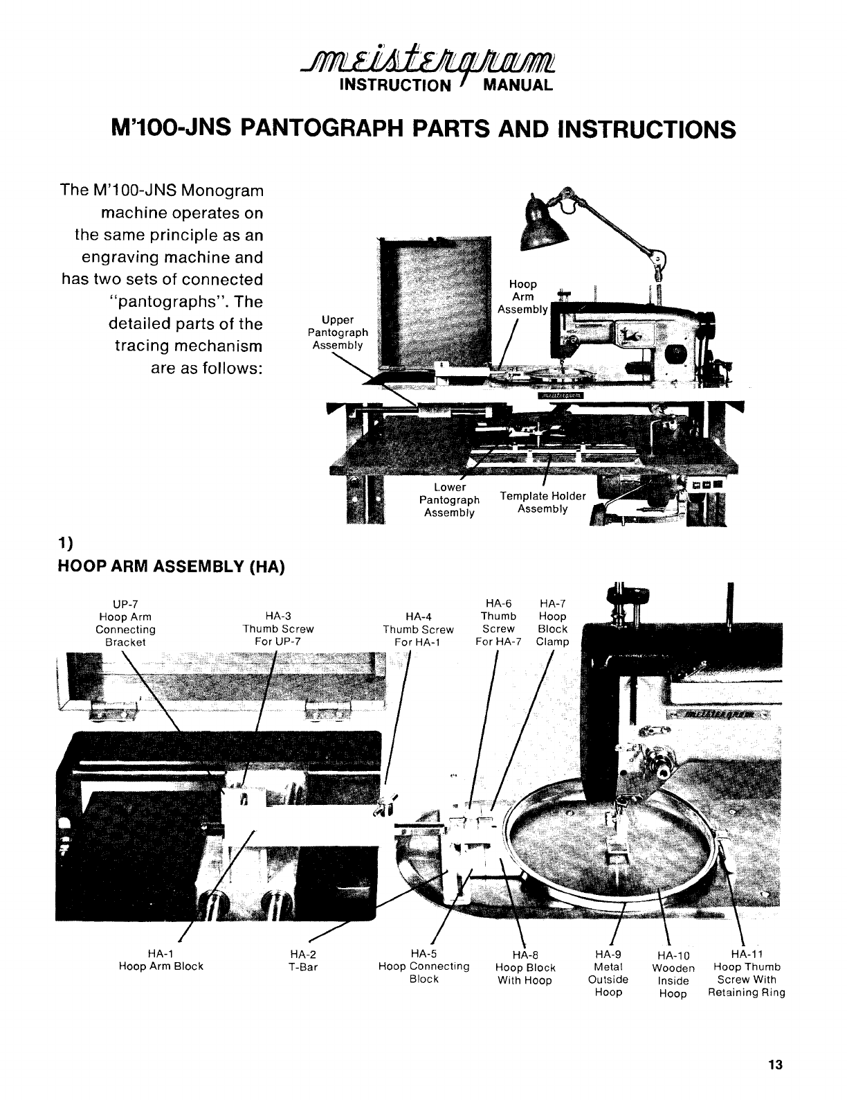
M'100-JNS PANTOGRAPH PARTS AND INSTRUCTIONS
The M'1 00-JNS Monogram
machine
operates on
the same
principle
as an
engraving machine and
has
two
sets
of
connected
"pantographs".
The
detailed parts
of
the
tracing
mechanism
are as
follows:
1)
HOOP ARM ASSEMBLY (HA)
HA-1
Hoop Arm
Block
HA-2
T-Bar HA-5
Hoop Connecting
Block
HA-8
Hoop
Block
With Hoop
HA-9
Metal
Outside
Hoop
HA-10 HA-11
Wooden Hoop Thumb
Inside Screw With
Hoop Retaining Ring
13
From the library of: Superior Sewing Machine & Supply LLC
14
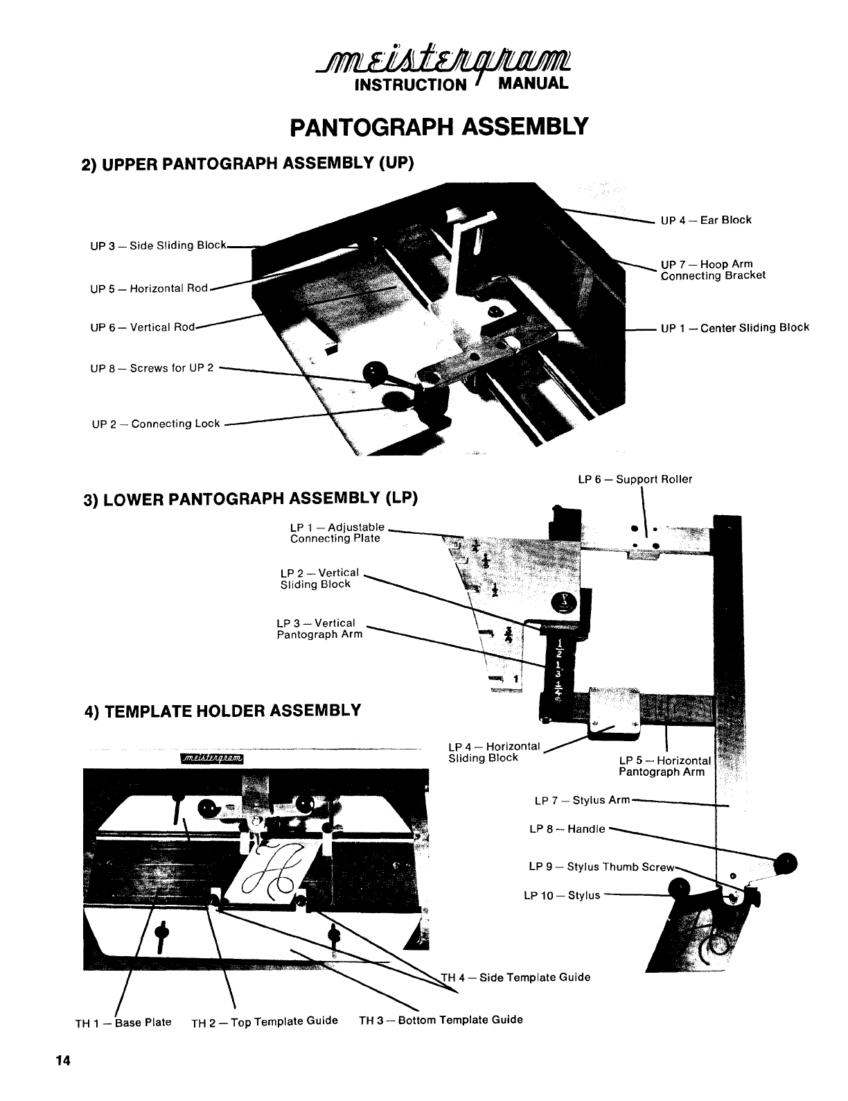
PANTOGRAPH ASSEMBLY
~UPPERPANTOGRAPHASSEMBLY(U~
UP
3-
Side
Sliding
Bloc
UP
6 - Vertical Rod
UP
8-
Screws
for
UP
2
UP
4-
Ear
Block
UP
7-
Hoop
Arm
Connecting
Bracket
UP
1
-Center
Sliding
Block
3) LOWER PANTOGRAPH ASSEMBLY (LP)
LP
6 -
su~C
Roller
LP
2-
Vertical
Sliding
Block
LP
3-
Vertical
Pantograph Arm
4) TEMPLATE HOLDER ASSEMBLY
LP
4 - Horizontal
Sliding
Block
LP
8-
Handle
LP
9-
Stylus Thumb S
4-
Side
Template
Guide
TH 1
-Base
Plate TH
2-
Top
Template
Guide
TH
3-
Bottom Template
Guide
From the library of: Superior Sewing Machine & Supply LLC

INSTRUCTIONS
M'100-J
PANTOGRAPH
ASSEMBLIES
refer
to
pages
12
&
13
1) HOOP
ARM
ASSEMBLY
(HA)
Install
Hoop
Arm
Assembly
by
attaching
HA
1
to
UP 7
with
thumb
screw
HA
3.
The
Hoop
Arm
provides
adjustment
in
three
different
directions:
a)
by
loosening
screw
HA
3,
the
assembly can be adjusted
up
or
down
for
various thicknesses
of
material.
Set
the
hoop
arm
so
that
the
block
on
the
hoop,
HA
8,
is
slightly
above
the
work
plate
when
the
material
is
in
the
hoop.
If
the
hoop
arm
is
too
low,
the
block
will
drag
on
the
plate.
If
too
high,
the
material
will
be
too
far
above
the
plate
and
not
allow
for
proper
stitching.
b)
by
loosening
thumb
screw
HA
4,
the
T-bar
can
be
adjusted
from
side
to
side
or
left
to
right.
This
enables
you
to
center
your
work
in
the
hoop,
or
in a
particular
area,
adjust
spacing
between
letters
and
to
make
monograms
vertically
or
diagonally.
Loosening
also enables
you
to
position
the
hoop
so
that
it
lies
flat
on
the
plate
and
is
not
tilted
toward
the
front
or
back.
c)
by
loosening
thumb
screw
HA
6,
the
hoop
can be
adjusted
from
front
to
back
which
enables
you
to
place
the
monograms
where
desired.
This
thumb
screw also enables
you
to
remove and
attach
the
hoop
to
the
clamp.
BE
SURE
THAT
ALL
SCREWS
ARE
SECURED
FIRMLY
TO
PREVENT
DISTORTED
MONOGRAMS
AND
IMPROPER
OPERATION
2) UPPER
PANTOGRAPH
ASSEMBLY
(UP)
The
Upper
Pantograph
acts
as
a
supporting
assembly between
the
Lower
Pantograph
and
the
Hoop
Arm
Assembly.
It's
smooth
sliding
action
is
possible
by
two
sets
of
rods and bearing-loaded
blocks.
The
Hoop
Arm
Assembly
is
to
be
connected
to
the
UP
on
part
UP
7.
The
Lower
Pantograph
is
to
be
connected
to
the
UP on
the
part
UP
2,
the
connecting
lock.
15
From the library of: Superior Sewing Machine & Supply LLC
16
There
are
two
sliding
blocks,
UP
3, and
into
each
block
is
inserted
the
ends
of
the
vertical
rods,
UP
6. These rods are secured
into
the
sliding
blocks
by
two
set screws,
located
on
the
bottom
of
each
block.
These set screws
must
be secure
to
keep
the
vertical
rods
from
moving
and causing
distortion
or
double
lines
in
the
monogram.
Be sure
to
check these screws,
to
make sure
they
have
not
loosened,
with
the
small allen
wrench
included
in
your
tool
kit.
Keep
both
sets
of
rods cleaned and
lightly
oiled.
3) LOWER
PANTOGRAPH
ASSEMBLY
(LP):
The Lower Pantograph
Assembly
(LP).
which
is attached to the Desk Ledge, acts
as
the
tracing
mechanism and governs the
movement
of
the hoop under the needle to
form
the monogram.
By'
adjusting
the vertical and horizontal
blocks
on the arms
of
the
LP,
the
movement
of
the
LP
is
reduced and results in
smaller
monograms.
This
is
an
exclusive feature
of
the
M'100-JNS.
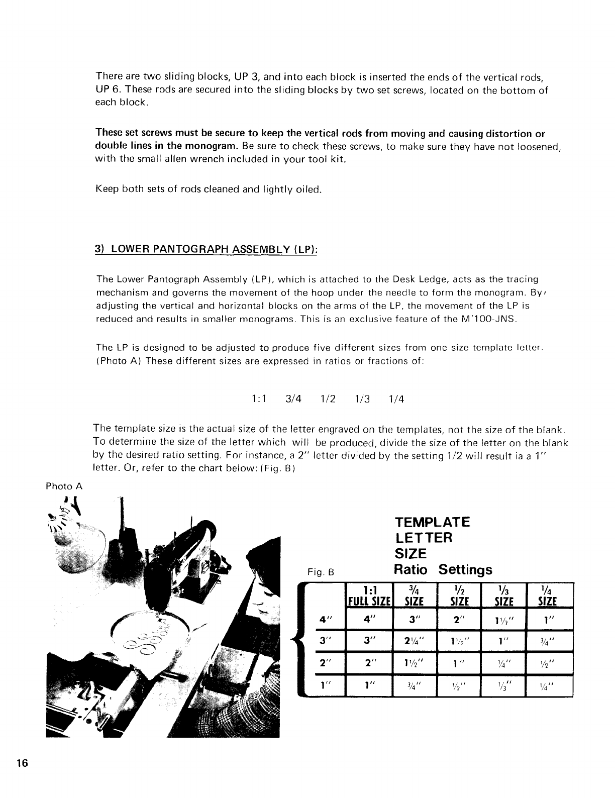
The
LP
is designed to be adjusted
to
produce
five
different
sizes
from
one size
template
letter.
(Photo A) These
different
sizes are expressed in ratios or
fractions
of:
1:1
3/4
1/2 1/3
1/4
The
template
size
is
the
actual
size
of
the
letter
engraved
on
the
templates,
not
the
size
of
the
blank.
To
determine
the
size
of
the
letter
which
will
be
produced,
divide
the
size
of
the
letter
on
the
blank
by
the
desired
ratio
setting.
For
instance, a
2"
letter
divided
by
the
setting
1/2
will
result
ia
a
1"
letter.
Or,
refer
to
the
chart
below:
(Fig. B)
Fig. B
1:1
lEULL
SIZE
4"
4"
~
3"
311
2"
211
1"
111
TEMPLATE
LETTER
SIZE
Ratio
Settings
3
/4
1f2
SIZE
SIZE
3"
2"
21//'
11/r;"
11/c/'
1
II
%"
1f'2''
lfl 1
/4
_S_IZE
SIZE
11//'
111
1"
%11
%"
1/'211
1I
11
13
1/4''
From the library of: Superior Sewing Machine & Supply LLC

(Lower
Pantograph
Assembly
continued)
You
will
find
these
ratio
settings
marked
on
the
adjustable
connecting
plate
(
LP
1),
the
vertical
arm
(
LP
3),
and
the
horizonta
I
arm
(
LP
5).
To
produce
different
size
letters
from
one
template,
you
must
change
the
ratio
settings
on
the
machine.
Follow
these steps
in
the
order
listed:
(Photo
C Pg.
18)
1)
Under
the
lid
on
the
table
top
is
the
Upper
Pantograph
Assembly.
Attached
to
the
large
center
sliding
block
(UP
1)
is
the
Connecting
Lock
(UP 2).
This
lock
is
connected
to
the
Adjustable
Connecting
Plate
(LP
1
).
Hold
the
plate
with
one hand and
turn
the
lock
handle
counter-clockwise,toward
the
back
of
the
machine,
to
loosen
the
lock.
Then,
push
the
lock
over
toward
the
left,
out
of
the
adjustable plate.
(PhotoDPg.18)
2) Grasp
the
connecting
plate
with
the
left
hand, and move
to
the
desired setting,
while
holding
the
horizontal
arm (LP 5)
stationary
with
the
right
hand.
The
adjustable
plate
is
attached
to
the
vertical
sliding
block
(
LP
2).
This
block
will
move along
the
arm
and
lock
at
each
ratio
setting.
The
front
edge
of
the
vertical
block
should be lined
up
with
the
ratio
setting
desired,
which
is
stamped on
the
vertical
arm.
(Photo
E Pg. 1
8)
3) Grasp
the
horizontal
pantograph
arm
(LP
5}
at
both
ends and push
horizontally,
to
the
left
or
right,
so
that
the
desired
ratio
setting lines
up
with
the
right
hand side
of
the
horizontal
block
(
LP
4).
The
horizontal
arm
has
the
same
ratio
settings
as
the
vertical
arm.
{Photo
C Pg.
18)
4)
Bring
the
connecting
lock
over
to
the
adjustable
plate
and
insert
lock
into
same
ratio
setting
slot
as
the
two
arms are set at.
Tighten
lock
very
securely,
by
turning
clockwise,
toward
front
of
the
machine.
IMPORTANT:
Be
sure
that
the
horizontal
arm,
vertical
arm
and
connecting
lock
are all located
at
the
same
ratio
setting.
If
one
of
these
three
settings are
not
the
same
it
will
result
in
a
distorted
monogram.
Be
sure
the
connecting
lock
is
secured
tightly
to
prevent
movement
of
the
plate,
when
locked,
or
this
will
also cause
distortion
of
the
monogram.
The
plate should swing
freely
when
not
connected
to
the
lock.
The
movement
of
the
vertical and
horizontal
sliding
blocks
is
governed
by
spring pressure
on
a
pin
inside each
block
(LP 2 and LP 4). These
pins
have been set
at
the
factory
prior
to
shipment,
however,
if
the
blocks
are
too
tight
to
move easily
or
too
loose
during
monogramming,
adjust
the
set screws
with
the
large allen
wrench
in
the
tool
kit.
Be
sure
that
all parts
of
the
Lower
Pantograph are
kept
clean and
lightly
oiled.
17
From the library of: Superior Sewing Machine & Supply LLC
18
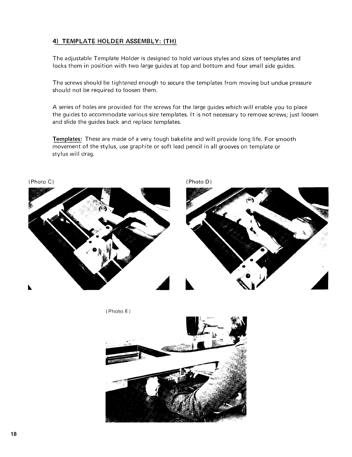
4)
TEMPLATE
HOLDER
ASSEMBLV: (TH)
The
adjustable
Template
Holder
is
designed
to
hold
various styles and sizes
of
templates
and
locks
them
in
position
with
two
large guides
at
top
and
bottom
and
four
small side guides.
The
screws should be
tightened
enough
to
secure
the
templates
from
moving
but
undue
pressure
should
not
be required
to
loosen
them.
A series
of
holes are
provided
for
the
screws
for
the
large guides
which
will
enable
you
to
place
the
guides
to
accommodate
various size templates.
It
is
not
necessary
to
remove screws;
just
loosen
and slide
the
guides back and replace templates.
Templates: These are made
of
a very
tough
bakelite
and
will
provide
long
life.
For
smooth
movement
of
the
stylus,
use
graphite
or
soft
lead pencil in all grooves on
template
or
stylus
will
drag.
(Photo
C)
(Photo
D)
(Photo
E)
From the library of: Superior Sewing Machine & Supply LLC
This manual suits for next models
1
Table of contents
Other Meistergram Sewing Machine manuals


