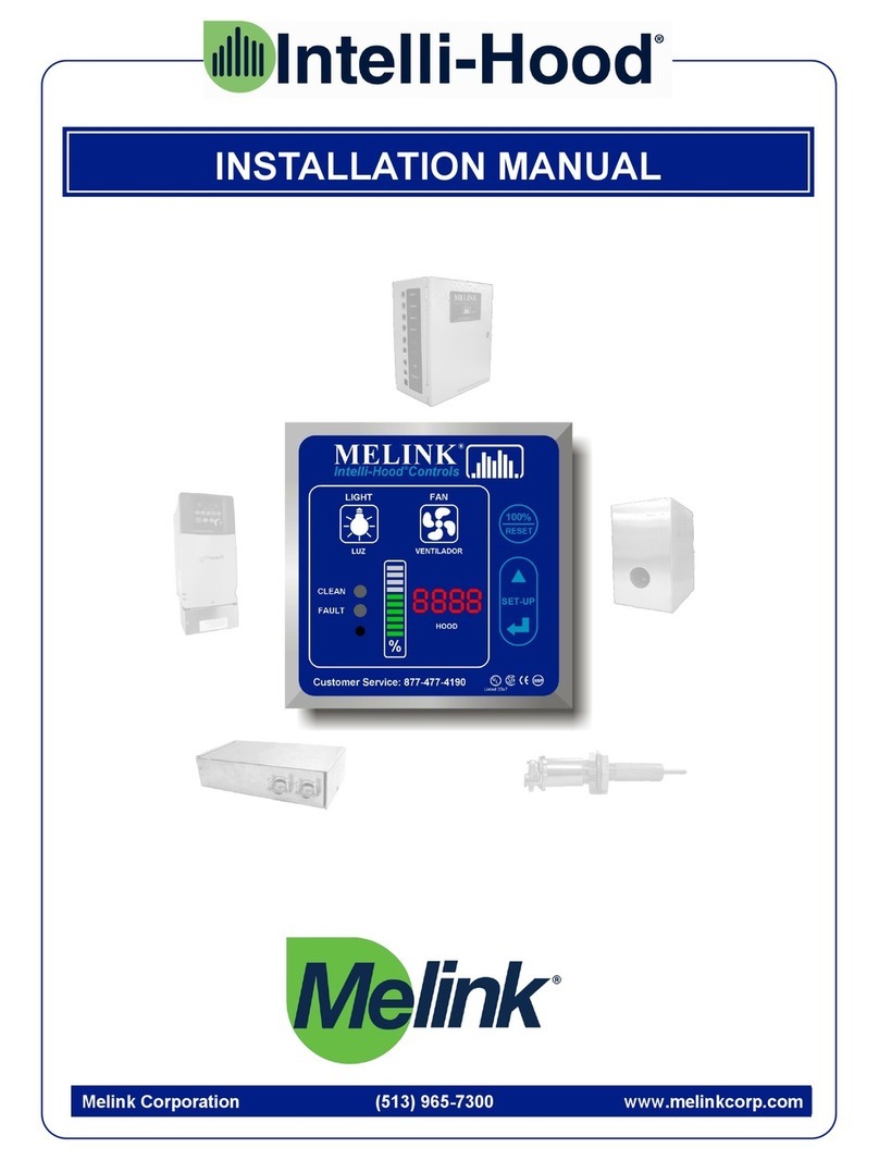
Melink Intelli-Hood Controls User manual

Melink Corporation (513) 527-7020 www.melinkcorp.com
REFERENCE GUIDE
Rev. 1.6


Table of Contents
Section 1: Intelli-Hood Operation and Simplissimo Settings
Section 2: Troubleshooting/ Component Compatibility
Section 3: Drive Connections
Section 4: Drive Programming
Section 5: Helpful Phone Numbers and Contact Information


Section 1:
Intelli-Hood Operation and
Simplissimo Settings


Operation/Service Specifications for Melink Intelli-Hood Operator
1-1
KEYPAD OPERATION
•LIGHTS Button - Turns hood lights on and off if I/O board output is tied into the hood light circuit. Also
turns APU blowers on and off.
•FANS Button - Turns the fans on and off. Also turns APU blowers on and off.
•BYPASS Button - Turns fans on in bypass mode. If the processor is running, then the 7-segment
display will show a 'E' for bypass mode and the bar graph will show VFD speed at 100% (blinking).
Also turns on APU blowers.
•SELECT (up & down arrows)
oIn SETUP mode, this switch will scroll through main menu item numbers (0-9) on the seven-
segment display and scroll through the setup selections on the bar graph.
oIn normal operating mode, this switch will display scrolling temperatures a single time for each
hood on the bar graph; after which it displays scrolling % fan speeds.
•ENTER
oIn SETUP mode, this switch will validate a selection.
oIn normal operating mode, this switch will display average VFD speed on the bar graph.
•To enter SETUP mode, press both the SELECT key and the ENTER key for 10 seconds.
•To restore setup defaults:
oMust be in setup mode.
oMust be at the flashing '0'.
oPress and hold the SELECT key for 10 seconds.
oA 'd' will show on the 7-segment display.
oHold the SELECT key for another 10 seconds.
oDefault data will be stored.
o2 beeps

Operation/Service Specifications for Melink Intelli-Hood Operator
1-2
•To reset average VFD speeds:
oMust be in setup mode.
oMust be at the flashing '0'.
oPress and hold the ENTER key for 10 seconds.
oA 'r' will show on the 7-segment display.
oHold the ENTER key for another 10 seconds.
oAverage VFD speeds will be reset.
o2 beeps
•To lock programming:
oPress and hold the both the SELECT key and the ENTER key for 10 seconds.
oDisplay a flashing '0'.
oPress and hold the both the SELECT key and the ENTER key for 10 seconds.
oA 'L' will show on the 7-segment display
oPress ENTER to exit setup mode
•To unlock programming:
oPress and hold the both the SELECT key and the ENTER key for 10 seconds.
oDisplay 'L'.
oPress and hold the both the SELECT key and the ENTER key for 10 seconds.
oA flashing '0' will show on the 7-segment display
oPress ENTER to exit setup mode
•Program Editing While Locked:
oOnly temperature spans can be changed while programming is in the locked state.
oPress and hold the both the SELECT key and the ENTER key for 10 seconds.
oDisplay 'L'.
oPress the SELECT key. The 'L' display will change to '1' which signifies hood #1.
oTo select a different hood, press the SELECT key. The '1' display will change to '2' which
signifies hood #2. Press SELECT again to change to hood #3 and so on.
oTo edit the temperature span of a particular hood, press the ENTER key when the
appropriate hood number is displayed. The bar graph will light showing the current
temperature span setting. Use the SELECT key to scroll to a different span. Press ENTER
to store the new span. The display will revert back to hood selection.
oTo exit programming, use the SELECT key to scroll to display 'L'. Press ENTER to exit
programming.
•Summer/Winter (3 Gang Coverplates Only)
oThis switch will activate the external heat circuit when closed. It will turn off the external heat
circuit when open.

Operation/Service Specifications for Melink Intelli-Hood Operator
1-3
Simplissimo Settings
Hood Settings
Exhaust Temp Span - This sets up the temperature span for modulating VFD speed between its set
minimum and maximum based on temperature. The span has a low value of 75oF and a maximum of up
to 150oF. Auto Span automatically sets the temperature span based on average VFD speeds over
periods of approximately one day (starting with the 75-110 setting).
Min Speed - This sets up the minimum speed that the VFD will run. Min speed must be less than
maximum speed. DF means that when fans are turned on, the fans will run at 100% for 1 minute and
then return to their normal minimum speed. Maximum minimum speed is 80%.
Max Speed - This sets up the maximum speed that the VFD will run. Max speed must be greater than
minimum speed. Minimum maximum speed is 50%.
Exhaust Temp. Alarm #1 - This sets up the first temperature set point for the 24 VDC exhaust alarm.
Set pt #1 must be less than set pt #2. If the operator tries to set up a set pt #1 greater than or equal to set
pt #2, the error beep will sound. When the setpoint is reached, and the bar graph corresponding to the
hood in alarm will flash and 24Vdc will be sent to the corresponding I/O board terminals. If a setting with
the AUD prefix is selected, then when the hood's speed is being displayed on the bar graph and the
exhaust temperature exceeds the temperature set point #1, the keypad's beeper will sound. The keypad
will go through 12 iterations of beeping the beeper for the alarm.
Exhaust Temp. Alarm #2 - This sets up the second temperature set point for the auxillary 24 VDC
output. Set pt #2 must be greater than set pt #1. If the operator tries to set up a set pt #2 less than or
equal to set pt #1, the error beep will sound. When the setpoint is reached, 24Vdc will be sent to
corresponding I/O board terminals.
No. Hood Sensors - This sets up the number of temperature sensors and optics for the given hood. The
hood can have from 1 to 4 temperature sensors and 1 optics sensor; or it can have from 1 to 4
temperature sensors only; or it can have just 1 optic sensor. Optic Channel 1 is always allocated to Hood
1, Optic Channel 2 is always allocated to Hood 2, and so on. Temperature Channel 1 is always allocated
to Hood 1, Temperature Channel 2 is always allocated to Hood 2, and so on.
Note: It is typically not good practice to connect temperature sensors from different hoods together since
the signal is averaged across all sensors connected to that particular channel, potentially having a
detrimental effect on system response to heat.
Auto Fan On/Off – Sets fans to either turn on or off automatically based on either temperature or a
preset timer (turns fans off after set number of hours). In Heat 0 or Heat 5, system will resume typical
operation when exhaust air temperature of any hood is greater than or equal to 90oF. If exhaust air
temperature is less than or equal to 75oF, while the system is on, the either a signal for either 0% or 5%
will be sent to the VFD. If all hoods are at this level, the system will turn off. Note: when fan button is
pressed, there is a ten minute delay until the temperature sensor becomes active for auto on/off
operation.
Send 4-20mA / 0-10V - This sets up the channel for which the VFD is connected for this hood. If 0, then
there is no VFD for the hood. VFD 1 - VFD 4 are outputs on the master Autocal board. VFD 5 - VFD 8
are outputs on the slave Autocal board. If Multiple is selected, then the VFD signal will follow that of the
previous hood (e.g. If Hood 1 is set up with VFD 1 as the output to its exhaust fan, the Hood 2 may be set
to multiple to follow VFD 1 for the supply fan).
Short Cycle Hood Ratio - This sets up the short cycle hood ratio.

Operation/Service Specifications for Melink Intelli-Hood Operator
1-4
System Settings
Auxiliary VFD Output - This sets up how the signal is determined for the auxiliary VFD output.
•No - No auxiliary output
•Average - send the average of the used VFDs on board.
•Highest - send the highest of the used VFDs on board
•Lowest - send the lowest of the used VFDs on board
•VFD1 - send the same signal that is going to VFD 1
•VFD2 - send the same signal that is going to VFD 2
•VFD3 - send the same signal that is going to VFD 3
•VFD4 - send the same signal that is going to VFD 4
Auxiliary VFD Input - This sets up how the VFDs will respond to the auxiliary 4-20 mA VFD input.
•No - No auxiliary input
•Add - Add aux input to each VFD output
•Sub - Subtract aux input from each VFD output
•Average - Average aux input with each VFD output
Hang Time - Amount of time fans will be left at max speed and smoke alarm will be activated after
detection of smoke.
Relay Input - If #1 (No), then the remote input terminals are used for nothing. If #2 (Remote On/Off),
then the remote input terminals are used for remotely turning the fans on and off. If settings 3 through 5
(3 through 9 on V4.5 chips) are used, then the remote input terminals are used as inputs for a relay.
When this relay is closed then the minimum speed of 50%, 75%, 90%, etc. is used instead of the
minimum speed called out in hood menu #2. The external heat circuit is activated when the relay is
closed. When the relay is open then the minimum speed in hood menu #2 is used and the external heat
circuit is turned off.
Bypass Timer - If item 2 - 10 are selected this sets the bypass timeout. This sets the amount of time to
leave the system in bypass mode after the bypass switch on the front panel is pressed. The dipswitch on
the Autocal II board must be in the bypass timer position. Bypass mode can be turned off by pressing the
bypass switch again. If item 1 is selected then bypass mode can only be turned off by pressing the
bypass switch again.
Comfort Mode - When the comfort mode is enabled: if kitchen temperature is > 75 and outside
temperature < 75, then the VFD speed is increased up to max speed with a ramp of 1 minute. If the
kitchen temperature cools to < 70 or the outside temperature increases to >75, then reduce the VFD
speed back to automatic control. The kitchen and outside temperature sensors can be wired to the I/O
board terminal block (item #3) or to Temp #3 (kitchen) and Temp #4 (outside) (selection #4). Selection #1
and #2 will disable the comfort mode. Selection #2 will allow the MUA temperature sensor to be wired to
Temp #4 for short cycle hoods.
Miscellaneous - If item #1 is selected then there are no miscellaneous functions enabled.
•Win SB (item #2) - If kitchen temperature is less than or equal to 70, then the temperature
span automatically increases to the next higher range. If the kitchen temperature is greater
than 75, then the temperature span automatically revert back to original set point.
•Int Bar (item #3) - The bargraph displays the speed that the system is sending to the drive
instead of reading the speed from the drive. This will disable the VFD fault capability.
Alarm #2 Output - This sets up the function of the auxiliary 24 VDC output.
•Temp - Output is used as temperature set point #2 alarm.
•Smoke - Output is used as a smoke alarm.
•Starter - Output is used as control for a magnetic motor starter. The motor starter is turned
on if any of the exhaust temperatures exceed 90oF or smoke is detected or BYPASS mode is

Operation/Service Specifications for Melink Intelli-Hood Operator
1-5
selected with the processor running. It will be turned off if all of the exhaust temperatures fall
below 85oF or after the hang time on the optics has expired. The motor starter can also
operate in conjunction with the auto mode such that it turns on and off automatically with
either heat or turns off after a selected time interval, all hoods must turn off to turn off the
motor starter and one hood must turn on to turn on the motor starter.
•Damper - Output is used to control a damper. When the fans are turned on the damper turns
on. When the fans are turned off the damper is off.
•Kitch<68 - Output is used to control a MUA heat unit. When the kitchen temperature is less
than 60 F, the MUA heat unit is on. When the kitchen temperature is greater than 65 F, the
MUA heat unit is off.
•Mom Rel - Output is used to control a momentary relay. When the fans are turned off, the
relay output is turned on for 3 seconds and then turned off.
•Fault (V4.5 only) – Output is energized whenever a fault is displayed on the keypad. (Note:
enabling the internal bar setting will disable VFD faults)
Optics Alignment - This will be entered when the installer is aligning the optics sensors. When hood 1 is
selected, then the 7-segment display will show a "1" and the bar graph will display the strength of the
signal being read by optics channel #1. Each bar will represent a return voltage of 0.3VDC. Ideally,
adjust gain on optics to read between three and seven bars of strength. Aligning hoods 2 - 8 will work in
the same manner.
DISPLAY MODES
Setup Mode - Displays setup information as the user enters it. It will stay in this mode until setup mode is
ended.
Display Average VFD Speed (Left arrow key [ENTER] pressed while not in SETUP)
•Bar graph will display ‘exponential average’ VFD speed (blinking) for each hood.
•7-segment display will display hood number (non-blinking).
•After all hoods have been displayed, the overall average speed will be displayed. The 7-
segment display will show a 'o'.
•Average VFD speed will be scaled to display 0 to 100% with each LED representing 10%.
•After all average VFD speeds have been displayed, the display mode will revert back to
NORMAL MODE.
Display Temperature (Up & Down arrow key [SELECT] pressed while not in SETUP)
•Bar graph will display temperature (non-blinking) for each hood.
•7-segment display will display hood number (non-blinking).
•After all hoods have been displayed, the kitchen temperature will be displayed. The 7-
segment display will show a 'c'. The outside temperature will be displayed next. The 7-
segment display will show a 'o'.
•Temperature will be displayed with only one bar representing the temperature level.
•After all temperatures have been displayed, the display mode will revert back to NORMAL
MODE.

Operation/Service Specifications for Melink Intelli-Hood Operator
1-6
Bar Graph VFD Speed Exhaust Temp
V3.7-V4.4/V4.5 Kitchen Temp
(c) Outside Temp (o) Optics Align.
Top 91-100% 146+/150+ 96+ 91+ 2.71+V
81-90% 141-145/140-149 91-95 81-90 2.41V-2.7V
71-80% 136-140/130-139 86-90 71-80 2.11V-2.4V
61-70% 131-135/120-129 81-85 61-70 1.81V-2.1V
51-60% 126-130/110-119 76-80 51-60 1.51V-1.8V
41-50% 121-125/100-109 71-75 41-50 1.21V-1.5V
31-40% 116-120/90-99 66-70 31-40 0.91V-1.2V
21-30% 111-115/80-89 61-65 21-30 0.61V-0.9V
11-20% 106-110/70-79 56-60 11-20 0.31V-0.6V
Bottom 0-10% 100-105/60-69 50-55 0-10 0.00V-0.3V
Normal Display Mode
•Bar graph will display VFD speed (non-blinking) for each hood.
•7-segment display will display hood number (non-blinking).
•If there is a fault with the hood currently being displayed then the hood number will be
displayed on the 7-segment display (non-blinking), the fault(s) will be displayed on the bar
graph (non-blinking), and the fault led will be ON.
A Temperature fault will light the bottom LED of the bar graph.
A VFD fault will light the second LED of the bar graph.
There will be 3 beeps every hour as long as there is a fault on any hood.
•If the BYPASS switch is pressed, then the 7-segment display will display 'E' and bar graph
will display VFD speed (blinking).
•If the hood being displayed is causing an alarm condition (exhaust or smoke), then the bar
graph and the 7-segment display will be blinking.
•If a given hood's optic channel cannot be calibrated, then the clean LED will flash green/red.
Otherwise the clean LED will be green.
•VFD speed will be scaled to display 0 to 100% with each LED representing 10%.
Calibration
•Fans will calibrate when they are turned on or every 24 hours if fans are running at minimum
speed at that given time. If fans are not running at minimum speed at the time recalibration is
supposed to occur after 24 hours, then calibration will wait for a subsequent 24 hour time
when the fans are running at minimum speed. If fans cannot calibrate after 3 days in
succession, then the clean LED will blink red/green and the fans will go to 100% speed.
•If any given optics channel cannot calibrate, the VFD associated with that hood will run at
100% speed and flash the clean LED red/green when this hood's VFD speed is being
displayed.

0 -NA
9 - NA
8 - NA
7 - NA
6 - NA
5 - NA
4 - Average
3 - Subtract
2 - Add
1 - No
%
10 - NA
9 - NA
8 - VFD4
7 - VFD3
6 - VFD2
5 - VFD1
4 - Lowest
3 - Highest
2 - Average
1 - No %
%
10 - NA
9 - NA
8 - NA
7 - Mom Rel
6 - Kitch<68
5 - Damper
4 - Starter
3 - Smoke
2 - Temp
1 - No
%
%%
0 - 75% DF
9 - 50% DF
8 - 80%
7 - 70%
6 - 60%
5 - 50%
4 - 40%
3 - 30%
2 - 20%
1 - 10%
10 - NA
9 - NA
8 - NA
7 - NA
6 - Bio-Link
5 - Thermostat &90%
4 - Thermostat &75%
3 - Thermostat &50%
2 - Remote On/Off
1 - No
10 - NA
9 - NA
8 - NA
7 - NA
6 - NA
5 - NA
4 - Yes -Temp #3 & #4
3 - Yes -Term #6,7,8,9,10
2 - No - S.Cycle Temp #4
1 - No
10 - NA
9 - NA
8 - NA
7 - NA
6 - NA
0 - Exit
4 Hood 4 etc
3 - Hood 3
2 - Hood 2
1 - Hood 1
0 -NA
9 - NA
8 - NA
7 - 180 Sec
6 - 90 Sec
5 - 60 Sec
4 - 25 Sec
3 - 15 Sec
2 - 10 Sec
1 - 5 Sec
HOOD
%
0 - Exit to Main Menu
9 - Short Cycle Hood Ratio
8 - Send 4-20ma / 0-10v
7 - Auto Fan - On/Off
6 - No. Hood Sensors
5 - Exhaust Temp. Alarm #2
4 - Exhaust Temp. Alarm #1
3 - Max. Fan Speed
2 - Min. Fan Speed
1 - Exhaust Temp. Span 0 - NA
9 - NA
8 - Auto Span
7 - 75-150F
6 - 75-140F
5 - 75-130F
4 - 75-120F
3 - 75-110F
2 - 75-100F
1 - 75-90F
%
0 - Exit to Main Menu
9 - Optics Alignment Check
8 - Alarm #2 Output (24vdc)
7 - Miscellaneous
6 - Comfort Mode Sensors
5 - Bypass Timer
4 - Relay Input (Dry)
3 - Optics Hang Time
2 - 4-20 ma Aux Input
1 - 4-20ma / 0-10v Aux Out
0 - AUD350F
9 - AUD300F
8 - AUD250F
7 - AUD200F
6 - AUD150F
5 - 350F
4 - 300F
3 - 250F
2 - 200F
1 - 150F
0- 8 Hr
9 - 7 Hrs
8 - 6 Hrs
7 - 5 Hrs
6 - 4 Hrs
5 - 3 Hrs
4 - 2 Hrs
3 - 1 Hr
2 - 30 Min
1 - No
%
10 - NA
9 - NA
8 - NA
7 - NA
6 - NA
5 - NA
4 - NA
3 - Int Bar
2 - Win SB
1 - No
%
0 - NA
9 - NA
8 - 80%
7 - 70%
6 - 60%
5 - 50%
4 - 40%
3 - 30%
2 - 20%
1 - No
%
%
MELINK
Intelli-Hood Operator
TM
0 - Exit Setup
9 - System
8 - Hood 8
7 - Hood 7
6 - Hood 6
5 - Hood 5
4 - Hood 4
3 - Hood 3
2 - Hood 2
1 - Hood 1
Main Menu Hood Menu
Selections
S
IMPLISSIMO
TM
%%%
%
Default Values are Underlined 124
%
0 - No
9 - Multiple
8 - VFD 8
7 - VFD 7
6 - VFD 6
5 - VFD 5
4 - VFD 4
3 - VFD 3
2 - VFD 2
1 - VFD 1
8 %
0- 14 Hrs
9 -12 Hrs
8 -10 Hrs
7 -8 Hrs
6 -6 Hrs
5 -4 Hrs
4 -2 Hrs
3 -Heat 5
2 -Heat 0
1 - No
7%
0 - No
9 -1O
8 -4T1O
7 -3T1O
6 -2T1O
5 -1T1O
4 -4T
3 -3T
2 -2T
1 -1T
6%
0 -NA
9 -NA
8 -NA
7 -NA
6 -400F
5 -350F
4 -300F
3 -250F
2 -200F
1 -150F
5
1234
5
6
7
8
9
System Menu
0 -100%
9 - 90%
8 - 80%
7 - 70%
6 - 60%
5 - 50%
4 - NA
3 - NA
2 - NA
1 - NA
%3
9
99
9
Version 01.01.01
(V4.4 Software)
%
1-7

0 -NA
9 - NA
8 - NA
7 - NA
6 - NA
5 - NA
4 - Average
3 - Subtract
2 - Add
1 - No
%
10 - NA
9 - NA
8 - VFD4
7 - VFD3
6 - VFD2
5 - VFD1
4 - Lowest
3 - Highest
2 - Average
1 - No %
%
0 - NA
9 - NA
8 - Fault
7 - Mom Rel
6 - Kitch<68
5 - Damper
4 - Starter
3 - Smoke
2 - Temp
1 - No
%
%%
0 - 75% DF
9 - 50% DF
8 - 80%
7 - 70%
6 - 60%
5 - 50%
4 - 40%
3 - 30%
2 - 20%
1 - 10%
0 - NA
9 - Thermostat &90%
8 - Thermostat &80%
7 - Thermostat &75%
6 - Thermostat &70%
5 - Thermostat &65%
4 - Thermostat &60%
3 - Thermostat &50%
2 - Remote On/Off
1 - No
10 - NA
9 - NA
8 - NA
7 - NA
6 - NA
5 - NA
4 - Yes -Temp #3 & #4
3 - Yes -Term #6,7,8,9,10
2 - No - S.Cycle Temp #4
1 - No
10 - NA
9 - NA
8 - NA
7 - NA
6 - NA
0 - Exit
4 Hood 4 etc
3 - Hood 3
2 - Hood 2
1 - Hood 1
0 -NA
9 - NA
8 - NA
7 - 180 Sec
6 - 90 Sec
5 - 60 Sec
4 - 25 Sec
3 - 15 Sec
2 - 10 Sec
1 - 5 Sec
HOOD
%
0 - Exit to Main Menu
9 - Short Cycle Hood Ratio
8 - Send 4-20ma / 0-10v
7 - Auto Fan - On/Off
6 - No. Hood Sensors
5 - Exhaust Temp. Alarm #2
4 - Exhaust Temp. Alarm #1
3 - Max. Fan Speed
2 - Min. Fan Speed
1 - Exhaust Temp. Span 0 - NA
9 - NA
8 - Auto Span
7 - 75-150F
6 - 75-140F
5 - 75-130F
4 - 75-120F
3 - 75-110F
2 - 75-100F
1 - 75-90F
%
0 - Exit to Main Menu
9 - Optics Alignment Check
8 - 24 VDC Output #1
7 - Miscellaneous
6 - Comfort Mode Sensors
5 - Bypass Timer
4 - Relay Input (Dry)
3 - Optics Hang Time
2 - 4-20 ma Aux Input
1 - 4-20ma / 0-10v Aux Out
0 - AUD350F
9 - AUD300F
8 - AUD250F
7 - AUD200F
6 - AUD150F
5 - 350F
4 - 300F
3 - 250F
2 - 200F
1 - 150F
0- 8 Hr
9 - 7 Hrs
8 - 6 Hrs
7 - 5 Hrs
6 - 4 Hrs
5 - 3 Hrs
4 - 2 Hrs
3 - 1 Hr
2 - 30 Min
1 - No
%
10 - NA
9 - NA
8 - NA
7 - NA
6 - NA
5 - NA
4 - NA
3 - Int Bar
2 - Win SB
1 - No
%
0 - NA
9 - NA
8 - 80%
7 - 70%
6 - 60%
5 - 50%
4 - 40%
3 - 30%
2 - 20%
1 - No
%
%
MELINK
Intelli-Hood Operator
TM
0 - Exit Setup
9 - System
8 - Hood 8
7 - Hood 7
6 - Hood 6
5 - Hood 5
4 - Hood 4
3 - Hood 3
2 - Hood 2
1 - Hood 1
Main Menu Hood Menu
Selections
S
IMPLISSIMO
TM
%%%
%
Default Values are Underlined 124
%
0 - No
9 - Multiple
8 - VFD 8
7 - VFD 7
6 - VFD 6
5 - VFD 5
4 - VFD 4
3 - VFD 3
2 - VFD 2
1 - VFD 1
8 %
0- 14 Hrs
9 -12 Hrs
8 -10 Hrs
7 -8 Hrs
6 -6 Hrs
5 -4 Hrs
4 -2 Hrs
3 -Heat 5
2 -Heat 0
1 - No
7%
0 - No
9 -1O
8 -4T1O
7 -3T1O
6 -2T1O
5 -1T1O
4 -4T
3 -3T
2 -2T
1 -1T
6%
0 -NA
9 -NA
8 -NA
7 -NA
6 -400F
5 -350F
4 -300F
3 -250F
2 -200F
1 -150F
5
1234
5
6
7
8
9
System Menu
0 -100%
9 - 90%
8 - 80%
7 - 70%
6 - 60%
5 - 50%
4 - NA
3 - NA
2 - NA
1 - NA
%3
9
99
9
Version 02.00.00
(V4.5 Software)
%
1-8

Section 2:
Troubleshooting And Component
Compatibility


OPTICS FAULT
3RD LED
CLEAN
FAULT HOOD
%
KEYPAD SHOWS
3RD LED AND
FAULT LIGHT
8
ITEMS TO CHECK:
TEMP FAULT
1ST LED
DRIVE FAULT
2ND LED
a. Determine which hood is not working - refer to digit next to bar graph.
b. Determine fan speed by counting # of bars illuminated on bar graph, if any.
c. Push 100% bypass switch to see if all fans go to full speed.
d. Check if exhaust fan on roof is running.
- Check if fan disconnect switch is turned on.
- Check if fan belt is adjusted for proper tension and replace if necessary.
- Check if motor is functional and replace if necessary.
a. Press the 100% bypass switch to return to the ‘auto mode’.
a. Press fan switch on Keypad to see if Keypad activates.
b. Check for tripped breaker that feeds the I/O Processor.
c. Open I/O Processor panel to verify power LED is on.
d. Check for tripped breaker inside I/O Processor. Reset if necessary.
a. Press fan switch on Keypad to see if Keypad activates.
b. Check breakers for I/O Processor and exhaust fans.
c. Check display on Drives for a fault (ie.. OC1,OH2).
e. Press the Drive reset switch, or turn off breaker and turn back on after 30 sec.
f. Refer to Troubleshooting @ Drive Keypad on other side.
a. Determine which hood has a ‘temp fault’ - refer to the digit next to bar graph.
b. Check cable connections between each Temp Sensor and I/O Processor.
c. Check to see if resistance at Temp Sensor is about 100 Ohms.
d. Check Simplissimo hood menu #6 is set to correct number of Temp Sensors.
a. Determine which hood has a ‘drive fault’ - refer to the digit next to bar graph.
b. Check cable connections between each Drive and I/O Processor.
c. Check display on Drives for a fault (i.e..OC1.OH2).
d. Press Drive reset switch, or turn off breaker and turn back on after 30 sec.
e. Refer to Troubleshooting @ Drive Keypad on other side.
a. Determine which hood needs Optics cleaned - refer to digit next to bar graph
b. Remove Optic covers for that hood and clean lenses with a clean soft cloth.
c. Press the fan switch off… and on again to recalibrate the Optics.
a. Check for blockage of infrared beam, i.e. cleaning rag or fire suppression pipe.
b. Check ‘gain’ switch on Optic receiver board to verify proper hood length.
c. Check alignment of Optics in Simplissimo System Menu #9.
d. Check cable connections between Optics and I/O Processor.
… press the fan switch off and on again to recalibrate the Optics.
.
KEYPAD
APPEARS
NORMAL
BUT FANS
NOT RUNNING
KEYPAD IS
BLANK AND
FANS ARE
RUNNING
KEYPAD IS
BLANK AND
FANS ARE
NOT RUNNING
KEYPAD
DISPLAYS
“E” AND
BARGRAPH
FLASHING
PROBLEM:
CLEAN
FAULT HOOD
%
CLEAN
FAULT HOOD
%
HOOD
CLEAN
FAULT HOOD
%
CLEAN
FAULT HOOD
%
CLEAN
FAULT HOOD
%
CLEAN
FAULT HOOD
%
HOOD
KEYPAD SHOWS
1ST LED AND
FAULT LIGHT
KEYPAD SHOWS
2ND LED AND
FAULT LIGHT
4
1
5
HOOD
CLEAN
FAULT %
CLEAN
LIGHT
FLASHES
RED/GREEN
7
2
3
6
TROUBLESHOOTING
@ MELINK KEYPAD
MELINK
Intelli-Hood Operator
R
Rev. 10-01
2-1

PROBLEM: ITEMS TO CHECK:
F4,
Under Voltage
TROUBLESHOOTING
@ DRIVE KEYPAD
MELINK
Intelli-Hood Operator
R
Esc Sel
PROGRAM
REV
RUN
FWD
FAULT
VOLTS
AMPS
HERTZ
a. Check AC power input to drive for low voltage or line power interruption.
a. Check AC power input to drive for high line voltage . Assure deceleration
time is set at 60 sec.
a. Output current to motor exceeds limit set by parameter P033. Check motor
and fan for conditions that may cause excessive motor current.
b. Check for appropriate Start Boost (A084).
a. Check to see if cooling fan is running. If not, replace fan.
b. Check for blocked or dirty heat sink fins. Verify that ambient temperature is
not over 104deg. F.
a. The drive output current has exceeded the hardware current limit. Check to
see if the drive is sized properly for the motor.
b. Check for appropriate Start Boost (A084).
a. Check the motor and external wiring for a grounded condition.
a. Drive rating of 150% for 1 min. or 200% for 3 sec. has been exceeded.
Reduce load or extend Acceleration time.
a. Check wiring to RS485 port
b. Check wiring connections
c. Verify I/O Processor is operating properly
Under Voltage
Over Voltage
Motor Overload
Heatsink
Over Temp.
Hardware
Overcurrent
Communication
Loss
Ground Fault
Drive Overlaod
F5,
Over Voltage
F7,
Motor Overload
F8,
Heatsink
Over Temp.
F12,
Hardware
Over Current
F13,
Ground Fault
F64,
Drive Overload
F81,
Communication
Loss
2-2

PROBLEM: ITEMS TO CHECK:
a. Remove run command to Drive by turning off fan switch on Melink Keypad.
Green light on Drive that says RUN should go out. Press PRG/RESET
on drive to remove fault. Or, turn off breaker to drive and then back
on again after 30 sec.
b. If OC 1 still occurs check if motor circuit is shorted or grounded.
c. If OC 1 still occurs verify that program for torque boost is set for fan
application (consult with Melink on exact function # based on Drive type).
d. If OC 1 still occurs verify that program for acceleration is set for minimum of
5-10 seconds (consult with Melink on exact function # based on Drive type).
a. Remove run command to Drive by turning off fan switch on Melink Keypad.
Press PRG/RESET on Drive to remove fault. Or, turn off breaker to Drive and
then back on again after 30 sec.
b. If OC2 still occurs check if motor circuit is shorted or grounded.
c. If OC 2 still occurs verify that program for deceleration is set for minimum of 60
seconds (consult Melink on exact function # based on Drive type).
a. Remove run command to Drive by turning off fan switch on Melink Keypad.
Press PRG/RESET on Drive to remove fault. Or, turn off breaker to Drive and
then back on again after 30 sec.
b. If OC3 still occurs check if motor circuit is shorted or grounded.
c. If OC3 still occurs check if there is a load fluctuation being caused by bad
bearings and or unevenly balanced fan wheel.
a. Remove run command to drive by turning off fan switch on Melink Keypad.
Press PRG/RESET on drive to remove fault. Or, turn off breaker to drive and
then back on again after 30 sec.
b. If OU still occurs verify that the actual supply voltage to the Drive is within the
allowable rated voltage of the Drive.
a. Remove run command to drive by turning off fan switch on Melink Keypad.
Press PRG/RESET on drive to remove fault. Or, turn off breaker to drive and
then back on again after 30 sec.
b. If OH2 still occurs verify there is continuity between the THR and CM terminals.
A jumper or NC relay for the fire suppression system should be installed.
a. Remove run command to drive by turning off fan switch on Melink Keypad.
Press PRG/RESET on drive to remove fault. Or, turn off breaker to drive and
then back on again after 30 sec.
b. If OL still occurs verify that program for overload protection is set at the FLA
rating of the motor (consult Melink on exact function # based on Drive type).
OC 1,
over current
during
acceleration
OC 2,
over current
during
deceleration
OC 3,
over current
at constant
speed
OU,
over voltage
protection
OH2,
external
alarm
input
OL,
overload
protection
TROUBLESHOOTING
@ DRIVE KEYPAD
MELINK
Intelli-Hood Operator
R
PANEL
CONTROL PRG. MODE RUN
VA
HZ
r/sis s/sis
RUN
STOP
FUNC
DATA
P R G
RESET
2-3

Operation/Service Specifications for Melink Intelli-Hood Operator
2-4
Advanced Troubleshooting
This section will deal with phenomena that are not mentioned in the standard troubleshooting guide. The
following actions take a more subjective approach to the problems.
General Procedure For Isolating Bad Components
Temperature Sensors
•Verify correct number of sensors are programmed for the hood and that all plug-n-play
connections are secure.
•Ensure no “Y” cables are plugged in at the IOP. Plugging temperature “Y” cables in at the IOP
can cause erratic behavior due to the wiring used internally. Always plug these in at the sensor.
•Check resistance between Pin 1 and Pin 2 at the end of the cable plugged into the IOP.
Resistance value should be approximately 109Ωper sensor. If there is more than one sensor,
multiply 109Ωby the number of temperature sensors for that hood to get an approximate value.
oIf resistance is incorrect, check temperature probe and cable individually to determine
problem component and replace as necessary.
oIf issue is low resistance (i.e. approximately half to a third of expected value) and a “Y” is
being used, verify that a temperature “Y” is in place and not an APU “Y”. The APU “Y”
will put the resistances in parallel, effectively reducing it to the point that the system will
never operate at more than minimum speed on temperature.
•If temperature faults are still present after these checks, it is possible that the problem is coming
from the optic circuit (this has been known to happen in the past). To check for this condition,
eliminate any optics on non-calibrated channels in the Simplissimo programming as well as
disconnecting the cables from the IOP. If the system now runs fine, the culprit is probably in the
optics portion. If the system does not work, it is possibly a bad Autocal board that may need to
be replaced.
Optic Sensors
•Verify that the correct optic channels are programmed for the given system.
•Check optics alignment in Simplissimo System Menu #9.
oIf a strong signal is present (4-8 bars), verify that breaking the beam reduces the signal to
one bar.
oIf a weak signal (2-3 bars) or no signal (1 bar) is present, increase the gain setting on the
receiver.
•If system is running at full speed for no apparent reason, try re-calibrating the optics (turning
system on and off). Also try programming out the optics and re-testing the system.
oIf the system runs normally in temperature only, but at full speed with the optics then
check the voltage output from the receiver. There should be 1-2 volts (DC) between the
ground post on the Autocal board and the respective receiver points on the Autocal. The
test points are labeled RCV0 through RCV3 for channels 1 through 4 respectively. If the
voltage is below one volt with the gain setting at the appropriate level, the optic boards
will need to be replaced.
•If possible, switch optic boards from malfunctioning channel with boards from a working optic
channel. If the problem jumps with the optic boards, then the problem is with either the emitter or
receiver. If the problem does not move, then the optic boards are fine and more checks need to
be made:
oIf possible, try to isolate if the problem is in the cables by switching the optics “Y” (with all
existing cables attached) with a working channel. If the problem moves at this point, then
the problem can most likely be attributed to a bad cable. If the problem does not move at
this point then the Autocal board is probably malfunctioning and should be replaced.
oCheck cables: Use a “pigtail plug” (female plug with wires that can be twisted together for
a continuity check) to short two pins together and check for continuity at the other end of
the cable. Also check for shorts to other pins. The optic channel uses pins 1, 2, and 3 on
the 4-pin cables. Replace any bad cables and retest system.
Other Melink Control System manuals
Popular Control System manuals by other brands
DX Engineering
DX Engineering Top Ten Devices OPSWAPPER quick start guide
NAVIS
NAVIS NavDP 4000 Series Operation manual

Mitsubishi Heavy Industries
Mitsubishi Heavy Industries SC-SLA3-ER Technical manual
ADB Safegate
ADB Safegate ACE2 user manual
Trinity Highway
Trinity Highway QuadGuard Elite M10 Product Description Assembly Manual
Roger
Roger CPR32-SE v2.0 operating manual

Extron electronics
Extron electronics TouchLink TLP Pro 520M user guide
Dill
Dill Retrofit TPMS manual
Hitachi
Hitachi YUTAKI ATW-YMM-01 Installation and operation manual
Condor
Condor 900 191 - V1.0 operating instructions
Carrier
Carrier ZONECC3ZAC01 Quick reference guide

Rise
Rise RANGER 500 installation manual
