Memorex MVD2009CB User manual

SERVICE MANUAL
MVD2009CB
Design and specifications are subject to change without notice.
COLORTELEVISION/DVDVIDEO PLAYER
ORIGINAL
MFR'S VERSION A

CAUTION:
DVD PLAYER IS A CLASS 1 LASER PRODUCT. HOWEVER THIS PLAYER USES A VISIBLE LASER
BEAM WHICH COULD CAUSE HAZARDOUS RADIATION EXPOSURE IF DIRECTED. BE SURE TO
OPERATE THE PLAYER CORRECTLY AS INSTRUCTED.
THE FOLLOWING CAUTION LABEL IS LOCATED ON THE REAR PANEL OF THE PLAYER.
WHEN THIS PLAYER IS PLUGGED TO THE WALL OUTLET, DO NOT PLACE YOUR EYES CLOSE
TO THE OPENING OF THE DISC TRAY AND OTHER OPENINGS TO LOOK INTO THE INSIDE OF
THIS PLAYER.
USE OF CONTROLS OR ADJUSTMENTS OR PERFORMANCE OF PROCEDURES OTHER THAN
THOSE SPECIFIED HEREIN MAY RESULT IN HAZARDOUS RADIATION EXPOSURE.
DO NOT OPEN COVERS AND DO NOT REPAIR YOURSELF. REFER SERVICING TO QUALIFIED
PERSONNEL.
IMPORTANTWARNING
Please include the following informations when you order parts. (Particularly the VERSION LETTER.)
1. MODEL NUMBER and VERSION LETTER
The MODEL NUMBER can be found on the back of each product and the VERSION LETTER can be
found at the end of the SERIAL NUMBER.
2. PART NO. and DESCRIPTION
You can find it in your SERVICE MANUAL.
HOWTO ORDER PARTS
SERVICING NOTICES ON CHECKING
As for the places which need special attentions,
they are indicated with the labels or seals on the
cabinet, chassis and parts. Make sure to keep the
indications and notices in the operation manual.
PERFORM A SAFETY CHECK AFTER
SERVICING
4.
Confirm that the screws, parts and wiring which
were removed in order to service are put in the
original positions, or whether there are the
portions which are deteriorated around the
serviced places serviced or not. Check the
insulation between the antenna terminal or
external metal and the AC cord plug blades.
And be sure the safety of that.
2. USE THE DESIGNATED PARTS
The parts in this equipment have the specific
characters of incombustibility and withstand
voltage for safety. Therefore, the part which is
replaced should be used the part which has
the same character.
Especially as to the important parts for safety
which is indicated in the circuit diagram or the
table of parts as a mark, the designated
parts must be used.
1. KEEP THE NOTICES 3. PUT PARTS AND WIRES IN THE
ORIGINAL POSITION AFTER
ASSEMBLING OR WIRING
There are parts which use the insulation
material such as a tube or tape for safety, or
which are assembled in the condition that
these do not contact with the printed board.
The inside wiring is designed not to get closer
to the pyrogenic parts and high voltage parts.
Therefore, put these parts in the original
positions.
A1-1
(Printed on the Rear Panel)
CLASS 1
LASER PRODUCT

A1-2
1.
2.
3.
Remove the Back Cabinet and AV PCB/DVD Block. (Refer to item 1 of the DISASSEMBLY
INSTRUCTIONS.)
Rotate the white gear of Deck CD section in the direction of the arrow by hand. (Refer to Fig. 1)
Draw the Tray.
DISC REMOVAL METHOD AT NO POWER SUPPLY
Fig. 1
Deck CDGear (White)
PARENTAL CONTROL - RATING LEVEL
4 DIGIT PASSWORD CANCELLATION
If the stored 4 digit password in the Rating Level menu needs to be cancelled, please follow the steps below.
Turn Unit ON.
Press and hold the 'STOP' key on the front panel.
Simultaneously press and hold the '7' key on the remote control unit.
Hold both keys for more than 3 seconds.
The On Screen Display message 'PASSWORD CLEAR' will appear.
The 4 digit password has now been cleared.
1.
2.
3.
4.
5.
6.
NB: The above procedure will reset ALL of the player's settings to the default factory state.

TABLE OF CONTENTS
IMPORTANT WARNING .........................................................................................................
SERVICING NOTICES ON CHECKING..................................................................................
HOW TO ORDER PARTS .......................................................................................................
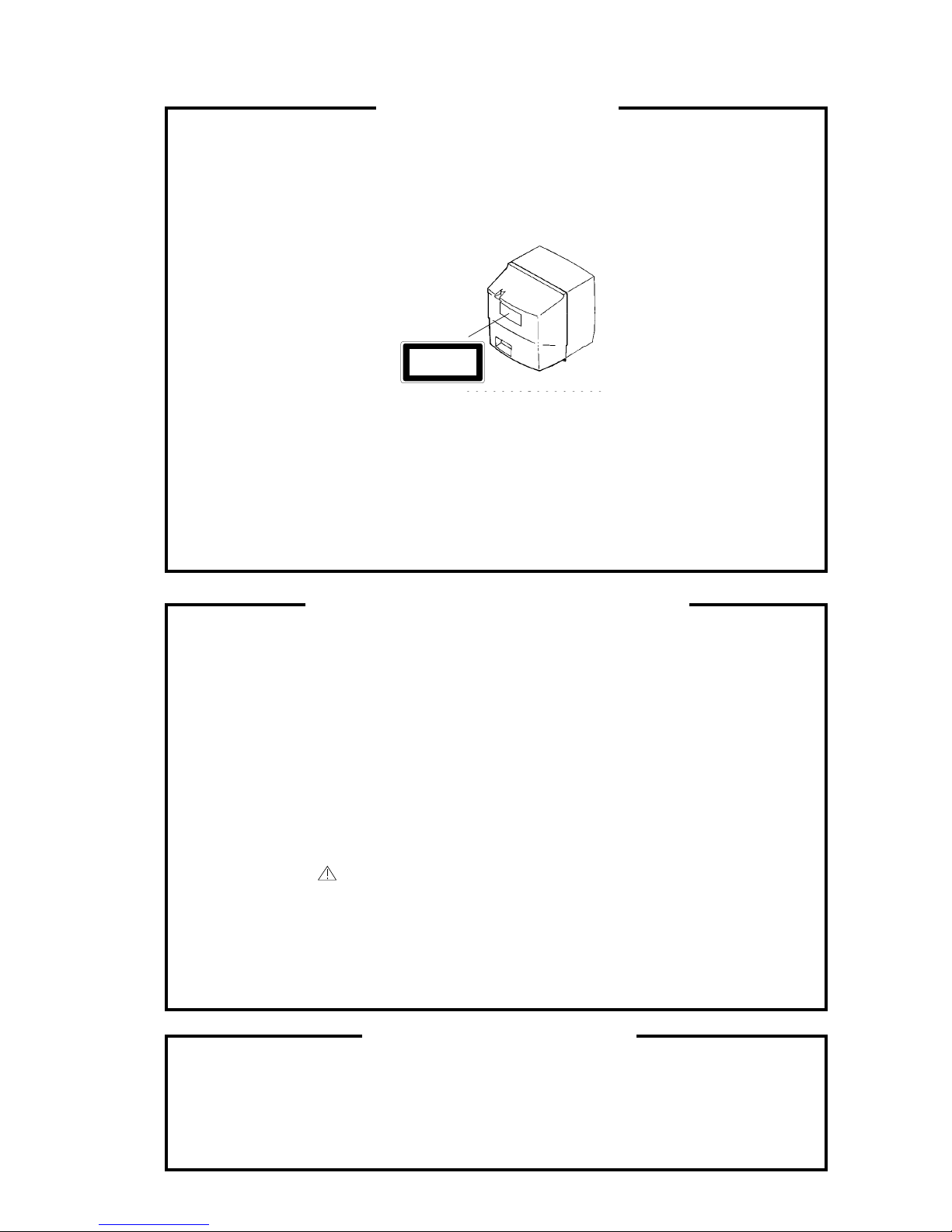
TAPE REMOVAL METHOD AT NO POWER SUPPLY .........................................................
DISC REMOVAL METHOD AT NO POWER SUPPLY ..........................................................
TABLE OF CONTENTS...........................................................................................................
GENERAL SPECIFICATIONS.................................................................................................
DISASSEMBLY INSTRUCTIONS
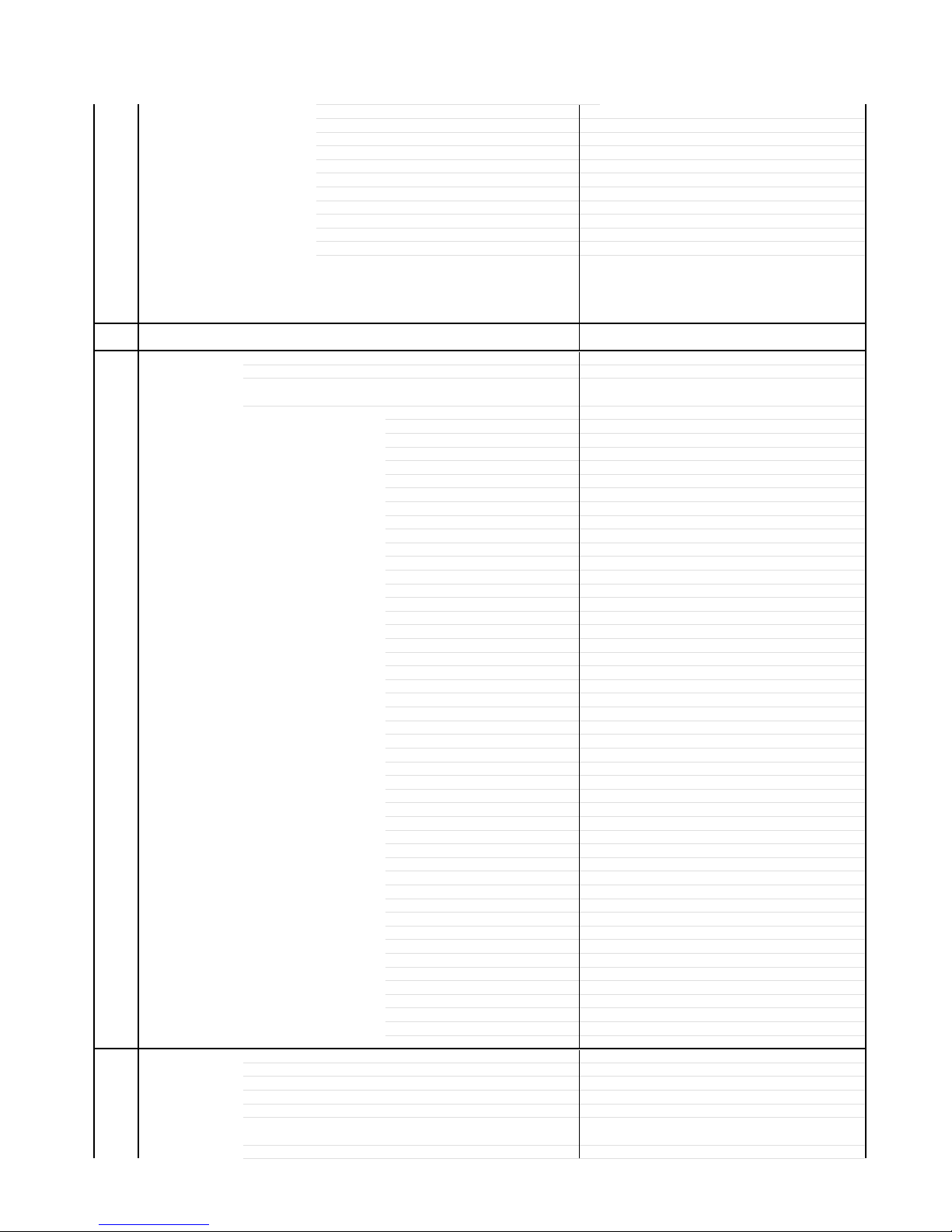
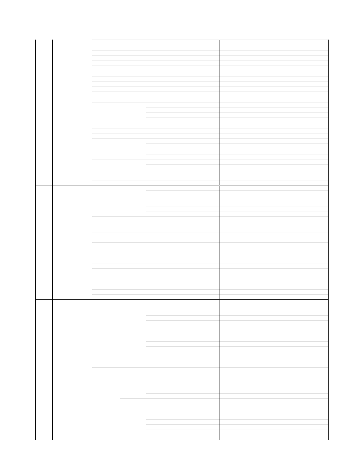
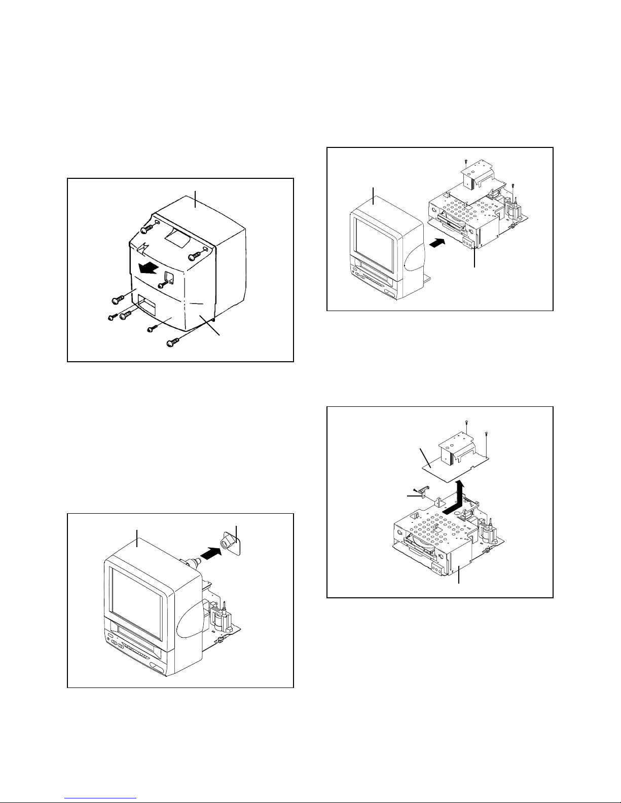
1. REMOVAL OF MECHANICAL PARTS AND P. C. BOARDS.........................................
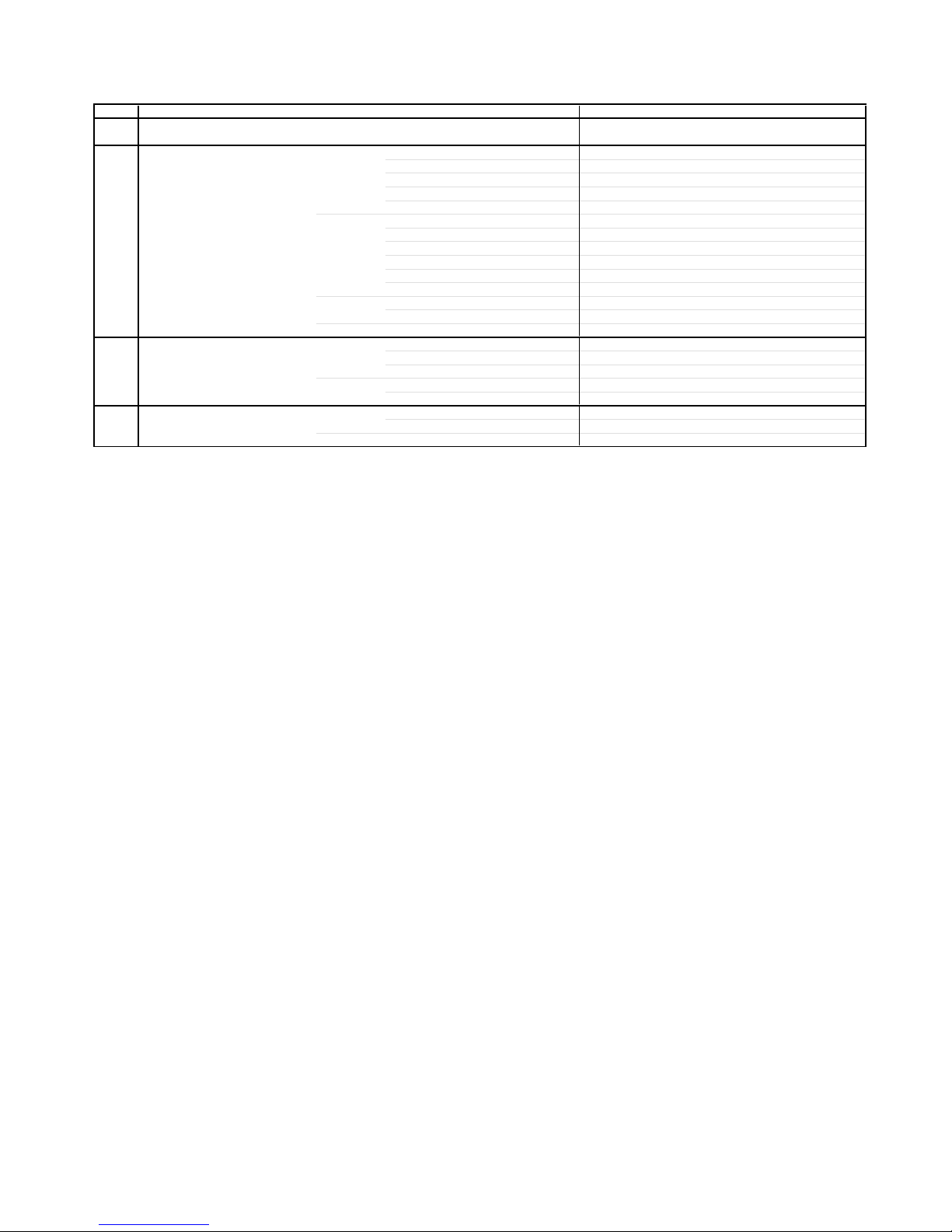
2. REMOVAL OF ANODE CAP...........................................................................................
3. REMOVAL AND INSTALLATION OF FLAT PACKAGE IC ............................................
SERVICE MODE LIST .............................................................................................................
CONFIRMATION OF HOURS USED ......................................................................................
WHEN REPLACING EEPROM (MEMORY) IC .......................................................................
SERVICING FIXTURES AND TOOLS ....................................................................................
ELECTRICALADJUSTMENTS.............................................................................................
BLOCK DIAGRAMS
DVD ST SOLUTION .............................................................................................................
TV .........................................................................................................................................
POWER ................................................................................................................................
PRINTED CIRCUIT BOARDS
DVD.......................................................................................................................................
AV/CRT.................................................................................................................................
POWER ................................................................................................................................
SCHEMATIC DIAGRAMS
RF_AMP/DSP .......................................................................................................................
MOTOR DRV ........................................................................................................................
MPEG....................................................................................................................................
MEMORY ..............................................................................................................................
AUDIO/VIDEO ......................................................................................................................
REGULATOR2......................................................................................................................
REGULATOR........................................................................................................................
MICON/TUNER ....................................................................................................................
CHROMA ..............................................................................................................................
SOUND AMP ........................................................................................................................
IN/OUT ..................................................................................................................................
STEREO ...............................................................................................................................
DEFLECTION .......................................................................................................................
CRT ......................................................................................................................................
POWER ................................................................................................................................
INTERCONNECTION DIAGRAM ............................................................................................
WAVEFORMS ..........................................................................................................................
MECHANICAL EXPLODED VIEWS........................................................................................
MECHANICAL REPLACEMENT PARTS LIST ......................................................................
ELECTRICAL REPLACEMENT PARTS LIST........................................................................
A1-1
A1-1
A1-1
A1-2
A1-2
A2-1
A3-1~A3-5
B1-1, B1-2
B2-1
B3-1, B3-2
C-1
C-1
C-2
C-2
D-1~D-6
E-1, E-2
E-3, E-4
E-5, E-6
F-1, F-2
F-3~F-6
F-7
G-1, G-2
G-3, G-4
G-5, G-6
G-7, G-8
G-9, G-10
G-11, G-12
G-13, G-14
G-15, G-16
G-17, G-18
G-19, G-20
G-21, G-22
G-23, G-24
G-25, G-26
G-27, G-28
G-29, G-30
G-31, G-32
H-1~H-3
I1-1, I1-2
J1-1
J2-1~J2-3
A2-1

GENERAL SPECIFICATIONS
G-1 TV CRT CRT Size / Visual Size 9 inch / 228.6 mmV
System CRT Type Normal
Deflection 90 degree
Magnetic Field BV/BH +0.45G / 0.18G
Color System NTSC
Speaker 2 Speaker
Position Side
Size 3 inch
Impedance 8 ohm
Sound Output Max 1.2W + 1.2W
10%(Typical) 0.8W + 0.8W
G-2 DVD System Color System NTSC
Disc DVD, CD-DA, CD-R/RW
Disc Diameter 120 mm , 80 mm
Deck Disc Loading System Front Loading
Motor 3 Motors
Pick up 1-Lens 2-Beams System
Playback time(Max) DVD DVD 1-Layer 135min (4.7GB)
DVD 2-Layer 245min (8.5GB)
CD 74min
Video CD --
Search speed Fwd 2-15 times / 4 step (DVD)
2-20 times / 4 step (CD)
Actual 2-45 times (DVD)
4-40 times (CD)
Rev 2-15 times / 4 step (DVD)
2-20 times / 4 step (CD)
Actual 2-45 times (DVD)
4-40 times (CD)
Slow speed Fwd 1/8-1/2 times
Actual --
Rev 1/8-1/2 times
Actual --
G-3 Tuning Broadcasting System US System M
System Tuner and System 1Tuner
Receive CH Destination US(w/CATV)
Tuning System F-Synth
Input Impedance VHF/UHF 75 Ohm
CH Coverage 2~69, 4A, A-5~A-1, A~I, J~W, W+1~W+84
Intermediate Picture(FP) 45.75MHz
Frequency Sound(FS) 41.25MHz
FP-FS 4.50MHz
Preset CH No
Stereo/Dual TV Sound US-Stereo
Tuner Sound Muting Yes
G-4 Signal Video Signal Input Level 1 V p-p/75 ohm
Output Level 1 V p-p/75 ohm
S/N Ratio (Weighted) 65dB
Horizontal Resolution at DVD Mode 400 Lines (TV Monitor)
500 Lines (Video Out)
RGB Signal Output Level --
Audio Signal Input Level -8.0dBm/50k ohm
Output Level
-8 dBm/ 1k ohm
(TV Mode,
0dB=0.775Vrms)
-12dBm/ 1k ohm
(DVD Mode, -
20dBFs
0dBFs=2.0Vrms)
Digital Output Level 0.5 V p-p/75 ohm
S/N Ratio at DVD (Weighted) 90 dB
Harmonic Distortion 0.06% (1kHz)
Frequency Response : at DVD 4Hz - 22kHz
at Video CD --
at CD 4Hz - 20kHz
G-5 Power Power Source AC 120V, 60Hz
DC 12 V
Power Consumption at AC 55W at 120V 60Hz
at DC 55W at 12V
Stand by (at AC) 5 W at 120V 60Hz
Per Year -- kWh/Year
Protector Power Fuse Yes
G-6 Regulation Safety UL
Radiation FCC
X-Radiation DHHS
Laser DHHS
G-7 Temperature Operation +
5
o
C
~ +4
0
o
C
Storage -2
0
o
C
~ +
60
o
C
A3-1

GENERAL SPECIFICATIONS
G-8 Operating Humidity Less than 80% RH
G-9 On Screen Menu(TV) Yes
Display Menu Type Icon
Picture Yes
Brightness Yes
Contrast Yes
Color Yes
Tint Yes
Sharpness Yes
Sound No
Bass No
Treble No
Balance No
CH Yes
TV/CATV Yes
Add/Delete Yes
Auto CH Memory Yes
Option Yes
V-Chip Yes
Language Yes
Open Yes
Close Yes
Clock No
Clock Set No
On/Off Timer No
Sleep Timer Yes
CH / AV(LINE) / DVD Yes
Stereo/Audio Output Yes
Bilingual No
SAP Yes
Caption / Text Yes
Auto Search/Position No
Game No
Volume Yes
Mute Yes
G-10 On Screen Menu (DVD) Yes
Display Menu Type Character
Language Yes
OSD Language Yes
Menu Yes
SubTitle Yes
Audio Yes
Picture Yes
TV Screen Size Yes
OSD Display On/Off Yes
Sound Yes
DRC (Dynamic Range Control) Yes
dts Decode No
Output(5.1ch/ 2ch) No
Surround On/Off No
Center On/Off No
Sub Woofer On/Off No
Parental Yes
Password Lock/ Un Lock Yes
Rating Level Yes
Open Yes
Close Yes
No disc Yes
Reading Yes
Play Yes
Still/Pause Yes
Stop Yes
Prohibit Mark Yes
Step Yes
Skip(>>|) Yes
Skip(|<<) Yes
Random Yes (CD)
Repeat Yes
Slow+ Yes
Slow- Yes
Search+ Yes
Search- Yes
Jump Yes
Resume Yes
Title No. Yes
Chapter No. Yes
Track No. Yes
A3-2

GENERAL SPECIFICATIONS
Time Yes
Sub Title No. Yes
Angle No. Yes
Vocal On/Off No
Audio No. Yes
Audio Stereo L/R No
Zoom Yes
Marker No. Yes
Program Play Back Yes (CD)
Surround On/Off No
Screen Saver No
MP3 Folder Name No
File Name No
File No No
Time No
Track No No
G-11 OSD Language (TV) English, French, Spanish
(DVD) English, French, Spanish
G-12 Remote Unit RC-DT
Control Glow in Dark Remocon No
Power Source Voltage(D.C) 3V
UM size x pcs UM-4 x 2 pcs
Keys Total Keys 46 Keys
Power Yes
1 Yes
2 Yes
3 Yes
4 Yes
5 Yes
6 Yes
7 Yes
8 Yes
9 Yes
0 Yes
Open/Close Yes
Play Yes
Stop Yes
Search+ Yes
Search- Yes
Skip+ Yes
Skip- Yes
Slow+ Yes
Slow- Yes
Still/Pause Yes
Display/Call Yes
TV/DVD Yes
Cancel Yes
Audio Select Yes
Angle Yes
Subtitle Yes
Top Menu Yes
Setup/TV Menu Yes
Return Yes
DVD Menu Yes
Up/ Set+/ CH Up Yes
Down/ Set-/ CH Down Yes
Left/Select- Yes
Right/Select+ Yes
Select/Enter Yes
Play Mode Yes
Marker Yes
Input Select Yes
Volme + Yes
Volme - Yes
Repeat A-B Yes
Zoom/ Quick View Yes
Mute Yes
Sleep Yes
Jump/Closed Caption Yes
G-13 Features CATV Yes
Auto Shut Off Yes
Auto Clock No
Just Clock No
Auto CH Memory Yes
V-Chip USA V-chip Yes
CANADA V-chip No
Auto Search No
A3-3

GENERAL SPECIFICATIONS
SAP Yes
Game Position No
FM Transmitter No
Energy Star No
Closed Caption Yes
Comb Filter No
Protect of FBT Leak Circuit No
Choke Coil No
Power On Memory No
Parental Lock (DVD Only) Yes
Tray Lock No
VIDEO CD Playback No
SVCD Playback No
Overlay Graphics And Text No
Command List No
Entry Point Jump No
MP3 Playback No
WMA Playback No
JPEG Playback No
Digital Out (Dolby Digital) Yes
(MPEG) Yes
(PCM) Yes
(DTS) Yes
Down Mix Out (Dolby Digital) Yes
(DTS) No
Surround (Tru Surround) No
Screen Saver No
Audio DAC 192kHz / 24bit
G-14 Accessories Owner's Manual Language English, Spanish
w/Guarantee Card No
Remote Control Unit Yes
Battery No
UM size x pcs --
OEM Brand --
Rod Antenna Yes
Poles 2 Poles
Terminal F Type
Loop Antenna No
Terminal --
U/V Mixer No
300 ohm to 75 ohm Antenna Adapter No
Antenna Change Plug No
Guarantee Card Yes
Registration Card No
Warranty Card No
ESP Card No
Service Station List No
DC Car Cord (Center+) Yes
Columbia Offer Sheet No
Carry 'Bag Yes (Supplied by a Buyer)
G-15 Interface Switch Front Power (Tact) Yes
Channel Up Yes
Channel Down Yes
Volume Up Yes
Volume Down Yes
Play Yes
Open/Close Yes
Skip(>>|) Yes
Skip(|<<) Yes
Still/Pause No
Stop Yes
Main Power SW No
Rear Main Power SW No
Indicator Power Yes (Red)
Stand-by No
On Timer No
Terminals Front Video Input RCA x 1
Audio Input RCA x 2(Stereo)
Other Terminal HeadPhone
Rear Video Input No
Audio Input No
Video Output RCA x 1
Audio Output RCA x 2(Stereo)
Digital Audio Output Coaxial (DVD Only)
Diversity No
DC Jack 12V(Center +) Yes
VHF/UHF Antenna Input F Type
A3-4

GENERAL SPECIFICATIONS
G-16 Set Size Approx. W x D x H (mm) 278x312.5x311.5
G-17 Weight Net (Approx.) 8.0 kg (17.6lbs)
Gross (Approx.) 11.5 kg (25.4lbs)
G-18 Carton Master Carton No
Content --- Sets
Material --- / ---
Dimensions W x D x H(mm) ---
Description of Origin ---
Gift Box Yes
Material Double/Brown
W/Color Photo Label No
Dimensions W x D x H(mm) 338 x 381 x 526
Design As Per Buyer 's
Description of Origin Yes
Drop Test Natural Dropping At 1 Corner / 3 Edges / 6 Surfaces
Height (cm) 62
Container Stuffing (40' container) 840 Sets
G-19 Material Cabinet Front PS 94V0 DECABROM
Rear PS 94V0 DECABROM
Jack Panel -
PCB Non-Halogen Demand No
Eyelet Demand Yes
G-20 Environment Pb Free Lead-free Solder No
Other No
Cd Free No
A3-5

DISASSEMBLY INSTRUCTIONS
B1-1
1. REMOVAL OF MECHANICAL PARTS
AND P.C. BOARDS
1-1: BACK CABINET (Refer to Fig. 1-1)
1.
2.
3.
4.
1-3: TV/DVD BLOCK (Refer to Fig. 1-3)
1.
2.
3.
Remove the 2 screws (1).
Disconnect the following connectors:
(CP301, CP302, CP401 and CP403).
Remove the TV/DVD Block in the direction of arrow.
Fig. 1-3
1-4: POWER PCB (Refer to Fig. 1-4)
1.
2.
3.
4.
5.
1-2: CRT PCB (Refer to Fig. 1-2)
CAUTION: BEFORE REMOVING THE ANODE CAP,
DISCHARGE ELECTRICITY BECAUSE IT
CONTAINS HIGH VOLTAGE.
BEFORE ATTEMPTING TO REMOVE OR
REPAIR ANY PCB, UNPLUG THE POWER
CORD FROM THE AC SOURCE.
1.
2.
3.
Remove the Anode Cap.
(Refer to REMOVAL OF ANODE CAP)
Disconnect the following connector:
(CP801).
Remove the CRT PCB in the direction of arrow.
Fig. 1-1
Fig. 1-2
Remove the 5 screws (1).
Remove the 2 screws (2).
Remove the screw (3).
Remove the Back Cabinet in the direction of arrow.
Front Cabinet
(1)
(2)
(1)
(2)
(1)
(3)
(1)
Back Cabinet
Front Cabinet CRT PCB
Remove the screw (1).
Remove the Main PCB Holder.
Remove the 2 screws (2).
Disconnect the following connectors:
(CP3802 and CP3803).
Remove the Power PCB in the direction of arrow.
Fig. 1-4
(1)
Main PCB Holder
(1)
(2)
TV/DVD Block
Front Cabinet
(1)
(1)
Power PCB
DVD Block
(2)

DISASSEMBLY INSTRUCTIONS
B1-2
1-5: FRONT TRAY PLATE/TOP SHIELD
(Refer to Fig. 1-5)
1.
2.
3.
4.
Fig. 1-6
Unlock the 2 supports (1).
Remove the Front Tray Plate in the direction of arrow (A).
Remove the 12 screws (2).
Remove the Top Shield in the direction of arrow (B).
Fig. 1-5
1-6: DVD PCB/DVD DECK (Refer to Fig. 1-6)
1.
2.
3.
4.
5.
6.
7.
8.
9.
Make the short circuit on the position as shown Fig. 1-6
using a soldering. If you remove the DVD Deck with no
soldering, the Laser may be damaged.
Disconnect the following connectors:
(CP8001 and CP8002).
Remove the 4 screws (1).
Remove the Angle Deck in the direction of arrow (A).
Disconnect the following connectors:
(CP2001, CP2301 and CP2302).
Remove the 4 screws (2).
Remove the DVD Deck in the direction of arrow (B).
Remove the 4 screws (3).
Remove the DVD PCB in the direction of arrow (C).
When the installation of the DVD Deck, remove all the
soldering on the short circuit position after the connection of
Pick Up PCB and DVD PCB connector.
NOTE
Top Shield
Front Tray Plate
(B)
(A)
(1) (1)
(2)
DVD Block
(2)
(2)
(2)
(2)
(2)
(2)
(2)
(2)
(2)
(2)
(2)
(3)
AV PCB
(1)
DVD Deck
(1)
(A)
(1)
(1)
(2)
(2)
(2)
(B)
(C)
Make the sort circuit
using a soldering.
Pick Up PCB
(2)
(3)
(3)
Angle Deck
DVD PCB
(3)
1-7: AV PCB (Refer to Fig. 1-7)
1.
2.
3.
Remove the screw (1).
Remove the screw (2).
Remove the AV PCB in the direction of arrow.
Fig. 1-7
(1)
AV PCB (2)
Bottom Plate

2. REMOVAL OF ANODE CAP
Read the following NOTED items before starting work.
After turning the power off there might still be a potential
voltage that is very dangerous. When removing the
Anode Cap, make sure to discharge the Anode Cap's
potential voltage.
Do not use pliers to loosen or tighten the Anode Cap
terminal, this may cause the spring to be damaged.
*
*
REMOVAL
1. Follow the steps as follows to discharge the Anode Cap.
(Refer to Fig. 2-1.)
Connect one end of an Alligator Clip to the metal part of a
flat-blade screwdriver and the other end to ground.
While holding the plastic part of the insulated Screwdriver,
touch the support of the Anode with the tip of the
Screwdriver.
A cracking noise will be heard as the voltage is discharged.
Flip up the sides of the Rubber Cap in the direction of
the arrow and remove one side of the support.
(Refer to Fig. 2-2.)
2.
GND on the CRT
Screwdriver
Alligator Clip
Support CRT
GND on the CRT
Rubber Cap
CRT Support
Fig. 2-1
Fig. 2-2
3. After one side is removed, pull in the opposite direction
to remove the other.
NOTE
DISASSEMBLY INSTRUCTIONS
INSTALLATION
1. Clean the spot where the cap was located with a small
amount of alcohol. (Refer to Fig. 2-3.)
NOTE
Confirm that there is no dirt, dust, etc. at the spot where
the cap was located.
2.
3.
Arrange the wire of the Anode Cap and make sure the
wire is not twisted.
Turn over the Rubber Cap. (Refer to Fig. 2-4.)
Fig. 2-4
4. Insert one end of the Anode Support into the anode
button, then the other as shown in Fig. 2-5.
CRT Support Fig. 2-5
5.
6. Confirm that the Support is securely connected.
Put on the Rubber Cap without moving any parts.
Location of Anode Cap
Fig. 2-3
Take care not to damage the Rubber Cap.
B2-1

Masking Tape
(Cotton Tape)
DISASSEMBLY INSTRUCTIONS
3.
REMOVAL
IC
Put the Masking Tape (cotton tape) around the Flat
Package IC to protect other parts from any damage.
(Refer to Fig. 3-1.)
1.
Fig. 3-1
NOTE
REMOVAL AND INSTALLATION OF
FLAT PACKAGE IC
Some ICs on the PCB are affixed with glue, so be
careful not to break or damage the foil of each IC
leads or solder lands under the IC when removing it.
NOTE
Masking is carried out on all the parts located within
10 mm distance from IC leads.
Blower type IC
desoldering machine
IC
Heat the IC leads using a blower type IC desoldering
machine. (Refer to Fig. 3-2.)
2.
Fig. 3-2
NOTE
Do not add the rotating and the back and forth
directions force on the IC, until IC can move back and
forth easily after desoldering the IC leads completely.
When IC starts moving back and forth easily after
desoldering completely, pickup the corner of the IC using
a tweezers and remove the IC by moving with the IC
desoldering machine. (Refer to Fig. 3-3.)
3.
Blower type IC
desoldering
machine
IC Fig. 3-3
Tweezers
Peel off the Masking Tape.4. Absorb the solder left on the pattern using the Braided
Shield Wire. (Refer to Fig. 3-4.)
5.
NOTE
Do not move the Braided Shield Wire in the vertical
direction towards the IC pattern.
Braided Shield Wire
Soldering Iron
Fig. 3-4
IC pattern
B3-1

DISASSEMBLY INSTRUCTIONS
Supply soldering
from upper position
to lower position
IC
Supply the solder from the upper position of IC leads
sliding to the lower position of the IC leads.
(Refer to Fig. 3-6.)
2.
Fig. 3-6
Soldering IronSolder
IC
Absorb the solder left on the lead using the Braided
Shield Wire. (Refer to Fig. 3-7.)
3.
Fig. 3-7
Soldering Iron
Braided Shield Wire
NOTE
Do not absorb the solder to excess.
IC
When bridge-soldering between terminals and/or the
soldering amount are not enough, resolder using a Thin-
tip Soldering Iron. (Refer to Fig. 3-8.)
4.
Fig. 3-8
Thin-tip Soldering Iron
NOTE
When the IC leads are bent during soldering and/or
repairing, do not repair the bending of leads. If the
bending of leads are repaired, the pattern may be
damaged. So, be always sure to replace the IC in this
case.
Finally, confirm the soldering status on four sides of the
IC using a magnifying glass.
Confirm that no abnormality is found on the soldering
position and installation position of the parts around the
IC. If some abnormality is found, correct by resoldering.
5.
Solder temporarily
Soldering Iron
INSTALLATION
Take care of the polarity of new IC and then install the
new IC fitting on the printed circuit pattern. Then solder
each lead on the diagonal positions of IC temporarily.
(Refer to Fig. 3-5.)
1.
Fig. 3-5
Solder temporarily
B3-2

C-1
SERVICE MODE LIST
This unit provided with the following SERVICE MODES so you can repair, examine and adjust easily.
To enter to the SERVICE MODE function, press and hold both buttons simultaneously on the main unit and on the remote
control for more than a standard time (second).
Set Key OperationsRemocon Key StandardTime
(seconds)
VOL. (-) MIN 0
VOL. (-) MIN 4
VOL. (-) MIN 6
VOL. (-) MIN 1
VOL. (-) MIN 9
Releasing of V-CHIP PASSWORD.
POWER ON total hours are displayed on the screen.
Refer to the "CONFIRMATION OF HOURS USED"
Can be checked of the INITIAL DATA of MEMORY IC.
Refer to the "WHEN REPLACING EEPROM (MEMORY) IC".
Display of the Adjustment MENU on the screen.
Refer to the "ELECTRICAL ADJUSTMENT" (On-Screen Display
Adjustment).
1
Initialization of the factory on TV.
NOTE: Do not use this for the normal servicing.
If you set a factory initialization, the memories are reset such as
the channel setting, and the POWER ON total hours.
1
1
1
1
Initialization of the factory on DVD.
NOTE: Do not use this for the normal servicing.
The function will only work without the setting of DVD disc at
DVD mode.
While pressing the Remocon Key for more than the Standard
Time, press the Set Key simultaneously.
Releasing of PARENTAL LOCK.
Refer to the "PARENTAL CONTROL - RATING LEVEL".
NOTE: The function will only work without the setting of DVD disc at
DVD mode.
While pressing the Remocon Key for more than the Standard
Time, press the Set Key simultaneously.
STOP 7 3
VOL. (-) MIN 8 Writing of EEPROM initial data.
NOTE: Do not use this for the normal servicing.
1
CONFIRMATION OF HOURS USED
POWER ON total hours can be checked on the screen. Total hours are displayed in 16 system of notation.
NOTE: If you set a factory initialization, the total hours is reset to "0".
1.
2.
3.
Set the VOLUME to minimum.
Press both VOL. DOWN button on the set and Channel
button (6) on the remote control for more than 1 second.
After the confirmation of using hours, turn off the power.
ADDRESS DATA
INIT 00 06
CRT ON 0010 Initial setting content of MEMORY IC.
POWER ON total hours.
= (16 x 16 x 16 x thousands digit value)
+ (16 x 16 x hundreds digit value)
+ (16 x tens digit value)
+ (ones digit value)
FIG. 1

C-2
WHEN REPLACING EEPROM (MEMORY) IC
If a service repair is undertaken where it has been required to change the MEMORY IC, the following steps should be taken to
ensure correct data settings while making reference to TABLE 1.
Table 1
1.
2. Enter DATA SET mode by setting VOLUME to minimum.
Press both VOL. DOWN button on the set and Channel button (6) on the remote control for more than 1 second.
ADDRESS and DATA should appear as FIG 1.
NOTE: No need setting for after INI 1F due to the adjustment value.
DVD Test Disc
(A-BEX TDV-540)
JG175A Ref. No.
JG175A Part No.
APJG175A00 Parts Name
DVD Test Disc
(A-BEX TDV-540)
Remarks
Tint adjustment of DVD mode
SERVICING FIXTURES AND TOOLS
3.
4.
5.
6.
7.
8.
9.
10.
11.
The unit will now have the correct DATA for the new MEMORY IC.
ADDRESS is now selected and should "blink". Using the RIGHT/LEFT button on the remote, step through the ADDRESS
until required ADDRESS to be changed is reached.
Press ENTER to select DATA. When DATA is selected, it will "blink".
Again, step through the DATA using RIGHT/LEFT button until required DATA value has been selected.
Pressing ENTER will take you back to ADDRESS for further selection if necessary.
Repeat steps 3 to 6 until all data has been checked.
When satisfied correct DATA has been entered, turn POWER off (return to STANDBY MODE) to finish DATA input.
After the data input, set to the initializing of shipping.
Turn POWER on.
Press both VOL. DOWN button on the set and Channel button (1) on the remote control for more than 1 second.
After the finishing of the initializing of shipping, the unit will turn off automatically.
ADDRESS DATA
INIT 00 06
CRT ON 0010
FIG. 1
06 00 44 00 D0 45 30 25 05 51
+0 +1 +2 +3 +4 +5 +6 +7 +8 +9 +A +B +C +D +E +FINI
30 70 05 05 88 03 60 00 78
01 00 41 50 0F 4700
10 60 56 FF 05 FF FF FF

ELECTRICAL ADJUSTMENTS
D-1
2. BASIC ADJUSTMENTS
Fig. 1-2
NO.
01
02
03
04
05
06
07
08
09
10
11
12
13
14
15
16
17
18
19
20
21
22
23
24
25
26
27
28
29
30
31
32
33
34
FUNCTION
CONT. AV(MIN)
COL. AV(CENT.)
COL. AV(MAX)
COL. AV(MIN)
TINT AV
SHARPNESS AV
SUB BIAS
BRI. DVD(CENT.)
BRI. DVD(MAX)
BRI. DVD(MIN)
CONT. DVD(CENT.)
CONT. DVD(MAX)
CONT. DVD(MIN)
COL. DVD(CENT.)
COL. DVD(MAX)
COL. DVD(MIN)
TINT DVD
SHARPNESS DVD
SUB BIAS
BRI. GAME(CENT.)
BRI. GAME(MAX)
BRI. GAME(MIN)
CONT. GAME(CENT.)
CONT. GAME(MAX)
CONT. GAME(MIN)
SUB BIAS
TUNING V MUTE
POWER ON V MUTE
INPUT LEVEL
SEPARATION L
SEPARATION H
X-RAY TEST
H.STOP
H.FREQ
NO.
35
36
37
38
39
40
41
42
43
44
45
46
47
48
49
50
51
52
53
54
55
56
57
58
59
60
61
62
63
64
65
66
67
68
FUNCTION
OSD H
OSD CONTRAST
CUT OFF
H POSITION
H.BLK L
H.BLK R
V SIZE
V POSITION
V LINEARITY
V S CORRECTION
V.COMP
R CUT OFF
G CUT OFF
B CUT OFF
R DRIVE
G DRIVE
B DRIVE
BRIGHTNESS(CENT.)
BRIGHTNESS(MAX)
BRIGHTNESS(MIN)
CONTRAST(CENT.)
CONTRAST(MAX)
CONTRAST(MIN)
COLOR(CENT.)
COLOR(MAX)
COLOR(MIN)
TINT
SHARPNESS
SUB BIAS
BRI. AV(CENT.)
BRI. AV(MAX)
BRI. AV(MIN)
CONT. AV(CENT.)
CONT. AV(MAX)
1.
Read and perform these adjustments when repairing the
circuits or replacing electrical parts or PCB assemblies.
CAUTION
•
•
•
•
Use an isolation transformer when performing any
service on this chassis.
Before removing the anode cap, discharge electricity
because it contains high voltage.
When removing a PCB or related component, after
unfastening or changing a wire, be sure to put the wire
back in its original position.
When you exchange IC and Transistor for a heat sink,
apply the silicon grease (YG6260M) on the contact
section of the heat sink. Before applying new silicon
grease, remove all the old silicon grease. (Old grease
may cause damages to the IC and Transistor).
BEFORE MAKING ELECTRICAL
ADJUSTMENTS
Prepare the following measurement tools for electrical
adjustments.
1. Oscilloscope
2. Digital Voltmeter
3. AC Voltmeter
4. Pattern Generator
5. Multi-Sound Signal Generator
On-Screen Display Adjustment
In the condition of NO indication on the screen.
Press the VOL. DOWN button on the set and the
Channel button (9) on the remote control for more than
1 second to appear the adjustment mode on the screen
as shown in Fig. 1-1.
1.
Fig. 1-1
Use the Channel UP/DOWN button or Channel button
(1-0) on the remote control to select the options shown
in Fig. 1-2.
Press the MENU button on the remote control to end
the adjustments.
2.
3.
Function
Step No.
2-1: CONSTANT VOLTAGE
1.
2.
3.
4.
5.
6.
Input DC12V to DC Jack and turn the Power ON.
Connect the digital voltmeter to the TP3801.
Set condition is AV MODE without signal.
Adjust the VR3801 until the digital voltmeter is 101 ±0.5V.
Input AC120V to AC cord, and then remove the DC Jack
cord.
Adjust the VR3802 until the digital voltmeter is 102 ±0.5V.
TV
01 OSD
15
2-4: CUT OFF
1.
2.
3.
4.
5.
6.
Adjust the unit to the following settings.
R CUT=7F, G CUT=7F, B CUT=7F, R DRV=3F,
G DRV=05, B DRV=3F
Place the set with Aging Test for more than 15 minutes.
Set condition is AV MODE without signal.
Using the remote control, set the brightness and contrast
to normal position.
Activate the adjustment mode display of Fig. 1-1 and
press the channel button (03) on the remote control to
select "CUT OFF".
Adjust the Screen Volume until a dim raster is obtained.
2-2: FOCUS
1.
2.
3.
Receive the monoscope pattern.
Turn the Focus Volume fully counterclockwise once.
Adjust the Focus Volume until picture is distinct.
1.
2.
3.
4.
Receive the VHF HIGH (70dB).
Connect the AC voltmeter to pin 6 of CP101.
Activate the adjustment mode display of Fig. 1-1 and
press the channel button (63) on the remote control to
select "LVL".
Press the RIGHT/LEFT button on the remote control
until the AC voltmeter is 80 ±2mV.
2-3: LEVEL

ELECTRICAL ADJUSTMENTS
D-2
2-9: VERTICAL LINEARITY
1.
2.
3.
4.
NOTE:
Receive the monoscope pattern.
Using the remote control, set the brightness and
contrast to normal position.
Activate the adjustment mode display of Fig. 1-1 and
press the channel button (09) on the remote control to
select "VLIN".
Press the RIGHT/LEFT button on the remote control
until the SHIFT quantity of the OVER SCAN on upside
and downside becomes minimum.
Adjust after performing adjustments in section 2-8.
After the adjustment of Vertical Linearity, reconfirm
the Vertical Position and Vertical Size adjustments.
2-6: HORIZONTAL POSITION
1.
2.
3.
4.
Receive the monoscope pattern.
Using the remote control, set the brightness and
contrast to normal position.
Activate the adjustment mode display of Fig. 1-1 and
press the channel button (04) on the remote control to
select "HPOSI".
Press the RIGHT/LEFT button on the remote control
until the SHIFT quantity of the OVER SCAN on right
and left becomes minimum.
2-7: VERTICAL POSITION
1.
2.
3.
Receive the monoscope pattern.
Using the remote control, set the brightness and
contrast to normal position.
Adjust the VR401 until the horizontal line becomes fit to
the notch of the shadow mask.
2-8: VERTICAL SIZE
1.
2.
3.
4.
5.
Receive the monoscope pattern.
Using the remote control, set the brightness and
contrast to normal position.
Activate the adjustment mode display of Fig. 1-1 and
press the channel button (07) on the remote control to
select "VSIZE".
Press the RIGHT/LEFT button on the remote control
until the Up/Down OVER SCAN Quantity becomes
equal to the Right/Left OVER SCAN Quantity.
Receive a broadcast and check if the picture is normal.
2-10: OSD HORIZONTAL
Activate the adjustment mode display of Fig. 1-1 and
press the channel button (01) on the remote control to
select "OSD".
Press the RIGHT/LEFT button on the remote control
until the difference of A and B becomes minimum.
(Refer to Fig. 2-1)
1.
2.
BA Fig. 2-1
01 OSD
15
2-5: WHITE BALANCE
NOTE: Adjust after performing CUT OFF adjustment.
1.
2.
3.
4.
5.
6.
7.
Place the set with Aging Test for more than 15 minutes.
Receive the gray scale pattern from the Pattern
Generator.
Using the remote control, set the brightness and
contrast to normal position.
Activate the adjustment mode display of Fig. 1-1 and
press the channel button (12) on the remote control to
select "R CUT".
Press the CH. UP/DOWN button on the remote control
to select the "R CUT", "G CUT", "B CUT", "R DRV" or
"B DRV".
Adjust the RIGHT/LEFT button on the remote control to
whiten the R CUT, G CUT, B CUT, R DRV, and B DRV
at each step tone sections equally.
Perform the above adjustments 5 and 6 until the white
color is looked like a white.
2-11: SEPARATION
1.
2.
3.
4.
5.
6.
7.
Set the multi-sound signal generator for each different
L-ch and R-ch frequency (Ex. L-ch=2KHz, R-ch=400Hz)
and receive the RF signal.
Connect the oscilloscope to the Audio Out Jack.
Press the AUDIO button on the remote control to set to
the stereo mode.
Activate the adjustment mode display of Fig. 1-1 and
press the channel button (64) on the remote control to
select "SEPAL".
Press the RIGHT/LEFT button on the remote control to
adjust it until the audio output wave becomes a fine
sine wave.
Press the CH UP button 1 time to set to "SEPAH"
mode.
Press the RIGHT/LEFT button on the remote control to
adjust it until the audio output wave becomes a fine
sine wave.
Method (1)
Please do the method (1) or method (2) adjustment.
1.
2.
3.
4.
5.
6.
7.
8.
9.
Set the multi-sound signal generator L-ch=1KHz, R-ch
=Non input and receive the RF signal.
Connect the oscilloscope to the Audio Out Jack (R-ch).
Press the AUDIO button on the remote control to set to
the stereo mode.
Activate the adjustment mode display of Fig. 1-1 and
press the channel button (64) on the remote control to
select "SEPAL".
Press the RIGHT/LEFT button on the remote control to
adjust it until the R-ch output becomes minimum.
Press the CH UP button 1 time to set to "SEPAH" mode.
Press the RIGHT/LEFT button on the remote control to
adjust it until the R-ch output becomes minimum.
Set the multi-sound signal generator L-ch=Non input,
R-ch=1KHz and receive the RF signal.
Connect the oscilloscope to the Audio Out Jack (L-ch).
Then perform the above adjustments 3~7.
Method (2)

ELECTRICAL ADJUSTMENTS
D-3
"A"
Fig. 2-2
2-13: TINT CENTER
1.
2.
3.
4.
5.
6.
7.
8.
9.
10.
11.
12.
13.
14.
Receive the color bar pattern. (RF Input)
Using the remote control, set the brightness, contrast,
color and tint to normal position.
Connect the oscilloscope to TP024.
Activate the adjustment mode display of Fig. 1-1 and
press the channel button (27) on the remote control to
select "TNTC".
Press the RIGHT/LEFT button on the remote control
until the section "A" becomes a straight line.
(Refer to Fig. 2-2)
Receive the color bar pattern. (Audio Video Input)
Press the INPUT SELECT button on the remote
control to set to the AV mode.
Using the remote control, set the brightness, contrast,
color and tint to normal position.
Activate the adjustment mode display of Fig. 1-1 and
press the channel button (39) on the remote control to
select "TNTCA".
Press the RIGHT/LEFT button on the remote control
until the section "A" becomes a straight line.
(Refer to Fig. 2-2)
Press the TV/DVD button on the remote control to set
to the DVD mode.
Playback the Title2 (color bar pattern) of JG175A.
Activate the adjustment mode display of Fig. 1-1 and
press the channel button (51) on the remote control to
select "TNTCD".
Press the RIGHT/LEFT button on the remote control
until the section "A" becomes a straight line.
(Refer to Fig. 2-3)
1.
2.
3.
4.
5.
6.
7.
8.
9.
10.
11.
12.
13.
14.
2-14: COLOR CENTER
Receive the color bar pattern. (RF Input)
Using the remote control, set the brightness, contrast,
color and tint to normal position.
Connect the oscilloscope to TP022.
Activate the adjustment mode display of Fig. 1-1 and
press the channel button (24) on the remote control to
select "COLC".
Adjust the VOLTS RANGE VARIABLE knob of the
oscilloscope until the range between white 100% and
0% is set to 4 scales on the screen of the oscilloscope.
Press the RIGHT/LEFT button on the remote control
until the red color level is adjusted to 90 ±5% of the
white level. (Refer to Fig. 2-4)
Receive the color bar pattern. (Audio Video Input)
Press the INPUT SELECT button on the remote control
to set to the AV mode.
Using the remote control, set the brightness, contrast,
color and tint to normal position.
Activate the adjustment mode display of Fig. 1-1 and
press the channel button (36) on the remote control to
select "COLCA".
Press the RIGHT/LEFT button on the remote control
until the red color level is adjusted to 90 ±5% of the
white level. (Refer to Fig. 2-4)
Press the TV/DVD button on the remote control to set
to the DVD mode.
Activate the adjustment mode display of Fig. 1-1 and
press the channel button (48) on the remote control to
select "COLCD".
Press the RIGHT/LEFT button on the remote control to
set the same step numbers as the AV.
Fig. 2-3
"A"
2-12: BRIGHT CENTER
1.
2.
3.
4.
5.
6.
7.
8.
9.
10.
.
Using the remote control, set the brightness and
contrast to normal position.
Activate the adjustment mode display of Fig. 1-1 and
press the channel button (18) on the remote control to
select "BRTC".
Press the RIGHT/LEFT button on the remote control
until the brightness step No. becomes "3A".
Press the INPUT SELECT button on the remote control
to set to the AV mode.
Using the remote control, set the brightness and
contrast to normal position.
Activate the adjustment mode display of Fig. 1-1 and
press the channel button (30) on the remote control to
select "BRTCA".
Press the RIGHT/LEFT button on the remote control
until the brightness step No. becomes "38".
Press the TV/DVD button on the remote control to set to
the DVD mode.
Activate the adjustment mode display of Fig. 1-1 and
press the channel button (42) on the remote control to
select "BRTCD".
Press the RIGHT/LEFT button on the remote control to
increase the step numbers by 5 steps to the AV.

ELECTRICAL ADJUSTMENTS
D-4
2-15: CONTRAST MAX
1.
2.
3.
4.
5.
6.
7.
8.
9.
10.
Activate the adjustment mode display of Fig. 1-1 and
press the channel button (22) on the remote control to
select "CNTX".
Press the RIGHT/LEFT button on the remote control
until the contrast step No. becomes "30"
Receive a broadcast and check if the picture is normal.
Press the INPUT SELECT button on the remote
control to set to the AV mode.
Activate the adjustment mode display of Fig. 1-1 and
press the channel button (34) on the remote control to
select "CNTXA".
Press the RIGHT/LEFT button on the remote control
until the contrast step No. becomes "31"
Receive a broadcast and check if the picture is normal.
Press the TV/DVD button on the remote control to set
to the DVD mode.
Activate the adjustment mode display of Fig. 1-1 and
press the channel button (46) on the remote control to
select "CNTXD".
Press the RIGHT/LEFT button on the remote control to
set the same step numbers as the AV.
2-16: SHARPNESS
1.
2.
3.
4.
5.
6.
7.
8.
Activate the adjustment mode display of Fig. 1-1 and
press the channel button (28) on the remote control to
select "SHRP".
Check if the step No.SHRP is "11".
Press the AV button on the remote control to set to the
AV mode.
Activate the adjustment mode display of Fig. 1-1 and
press the channel button (40) on the remote control to
select "SHARPA".
Check if the step No.SHRP is "11".
Press the DVD button on the remote control to set to the
DVD mode.
Activate the adjustment mode display of Fig. 1-1and
press the channel button (52)on the remote control to
select "SHARPD".
Check if the step No.SHRP is "05".
Fig. 2-4
White 0%
White 100%
100%
Red Level
2-18: Confirmation of Fixed Value (Step No.)
Please check if the fixed values of the each adjustment
items are set correctly referring below.
NO.
02
05
06
08
10
11
16
19
20
21
23
25
26
29
31
32
33
35
37
STEP NO.
00
00
00
04
0C
03
05
58
25
25
00
70
05
00
58
25
25
00
70
FUNCTION
OSD CONTRAST
H.BLK L
H.BLK R
V POSITION
V S CORRECTION
V.COMP
G DRIVE
BRIGHTNESS(MAX)
BRIGHTNESS(MIN)
CONTRAST(CENT.)
CONTRAST(MIN)
COLOR(MAX)
COLOR(MIN)
SUB BIAS
BRI. AV(MAX)
BRI. AV(MIN)
CONT. AV(CENT.)
CONT. AV(MIN)
COL. AV(MAX)
NO.
38
41
43
44
45
47
49
50
53
55
56
57
59
60
61
62
68
STEP NO.
05
00
58
25
25
00
70
05
00
58
25
25
00
00
00
40
3F
FUNCTION
COL. AV(MIN)
SUB BIAS
BRI. DVD(MAX)
BRI. DVD(MIN)
CONT. DVD(CENT.)
CONT. DVD(MIN)
COL. DVD(MAX)
COL. DVD(MIN)
SUB BIAS
BRI. GAME(MAX)
BRI. GAME(MIN)
CONT. GAME(CENT.)
CONT. GAME(MIN)
SUB BIAS
TUNING V MUTE
POWER ON V MUTE
H.FREQ
2-17: OSD CONTRAST
1.
2.
Activate the adjustment mode display of Fig. 1-1 and
press the channel button (02) on the remote control to
select "OSD C".
Check if the step No.OSD C is "00".
Other manuals for MVD2009CB
2
Table of contents
Other Memorex TV DVD Combo manuals

Memorex
Memorex MVUC821 - DVD LCD TV Kitchen Clock Radio User manual

Memorex
Memorex MLTD2622 - 26" LCD TV User manual

Memorex
Memorex MVDT2402 User manual

Memorex
Memorex MVD2019 User manual

Memorex
Memorex MVD1402 User manual

Memorex
Memorex MVD1402 User manual

Memorex
Memorex MVDT2002A User manual

Memorex
Memorex MVD1301OM User manual

Memorex
Memorex MVD2019 User manual

Memorex
Memorex MVD2113 User manual