A2-1
TABLE OF CONTENTS
A1-1
A1-1
A1-1
A1-2
A1-2
A2-1
A3-1~A3-5
B1-1, B1-2
B2-1, B2-4
B3-1
B4-1, B4-2
C-1
C-1
C-2
D-1~D-6
E-1, E-2
E-3, E-4
E-5, E-6
F-1, F-2
F-3~F-6
F-7, F-8
G-1, G-2
G-3, G-4
G-5, G-6
G-7, G-8
G-9, G-10
G-11, G-12
G-13, G-14
G-15, G-16
G-17, G-18
G-19, G-20
G-21, G-22
G-23, G-24
G-25, G-26
G-27, G-28
G-29, G-30
G-31, G-32
G-33, G-34
H-1~H-3
I1-1, I1-2
I2-1
J1-1
J2-1
J3-1~J3-3
K-1
IMPORTANT WARNING ........................................................................................................
SERVICING NOTICES ON CHECKING..................................................................................
HOW TO ORDER PARTS .......................................................................................................
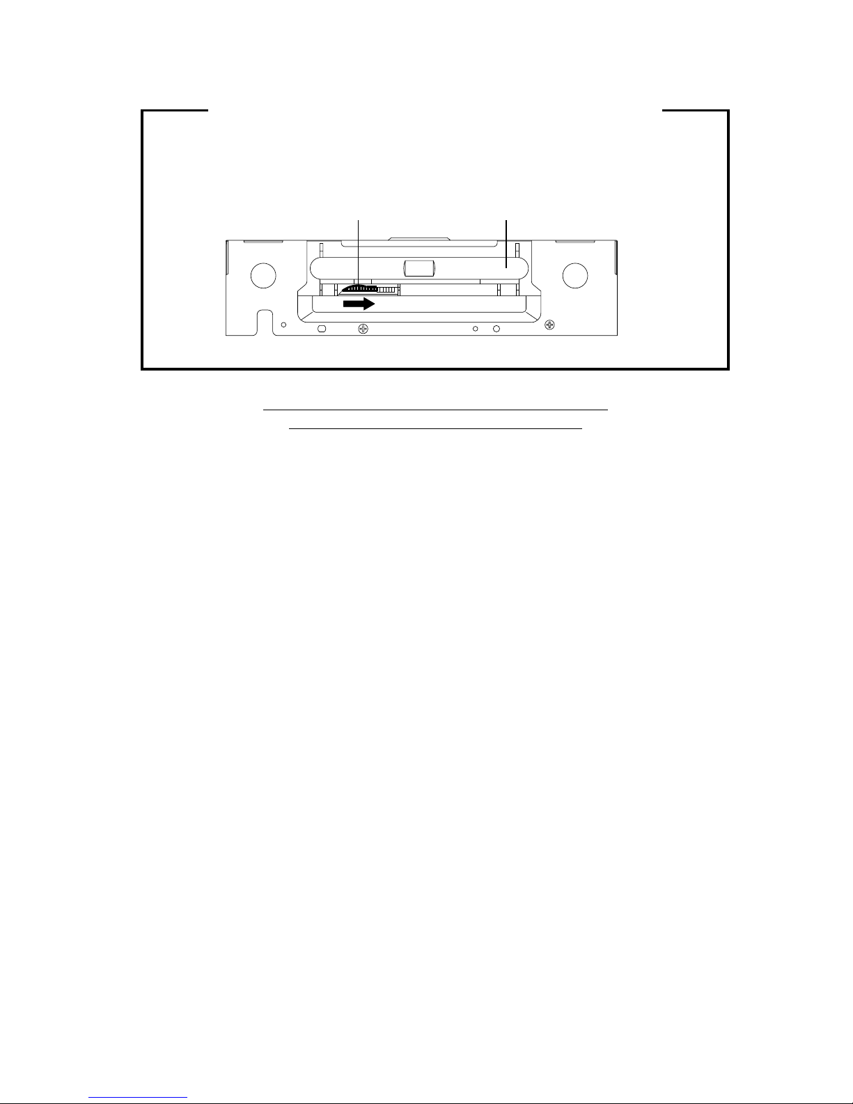
DISC REMOVAL METHOD AT NO POWER SUPPLY .........................................................
PARENTAL CONTROL-RATING LEVEL ..............................................................................
TABLE OF CONTENTS..........................................................................................................
GENERAL SPECIFICATIONS................................................................................................
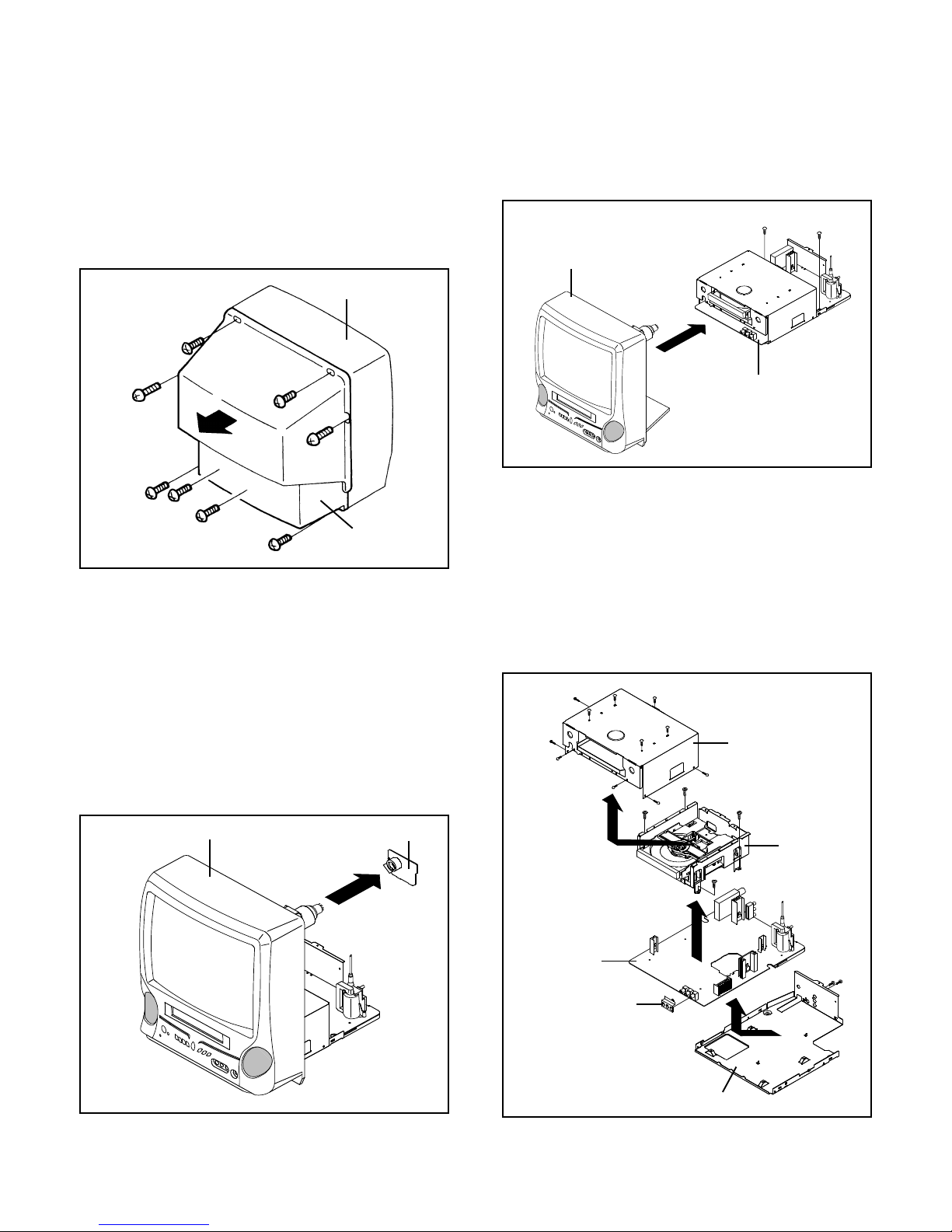
DISASSEMBLY INSTRUCTIONS
1. REMOVAL OF MECHANICAL PARTS AND P.C. BOARDS ...........................................
2. REMOVAL OF DVD DECK PARTS .................................................................................
3. REMOVAL OF ANODE CAP ...........................................................................................
4. REMOVAL AND INSTALLATION OF FLAT PACKAGE IC .............................................
SERVICE MODE LIST.............................................................................................................
CONFIRMATION OF HOURS USED ......................................................................................
WHEN REPLACING EEPROM (MEMORY) IC .......................................................................
ELECTRICAL ADJUSTMENTS ..............................................................................................
BLOCK DIAGRAMS
DVD......................................................................................................................................
TV.........................................................................................................................................
POWER................................................................................................................................
PRINTED CIRCUIT BOARDS
DVD......................................................................................................................................
AV/CRT ................................................................................................................................
RELAY/SW/FG.....................................................................................................................
SCHEMATIC DIAGRAMS
RF_AMP/DSP ......................................................................................................................
MOTOR DRV .......................................................................................................................
MPEG...................................................................................................................................
MEMORY .............................................................................................................................
AUDIO/VIDEO ......................................................................................................................
REGULATOR2 .....................................................................................................................
REGULATOR.......................................................................................................................
MICON/TUNER ....................................................................................................................
VIF/SIF/CHROMA ................................................................................................................
SOUND AMP .......................................................................................................................
IN/OUT .................................................................................................................................
STEREO ..............................................................................................................................
DEFLECTION ......................................................................................................................
CRT......................................................................................................................................
POWER ...............................................................................................................................
SW/RELAY/FG ....................................................................................................................
INTERCONNECTION DIAGRAM ...........................................................................................
WAVEFORMS .........................................................................................................................
MECHANICAL EXPLODED VIEW ..........................................................................................
DVD DECK EXPLODED VIEW ...............................................................................................
MECHANICAL REPLACEMENT PARTS LIST ......................................................................
DVD DECK REPLACEMENT PARTS LIST ............................................................................
ELECTRICAL REPLACEMENT PARTS LIST ........................................................................
SERIAL NUMBER CODE........................................................................................................