MEN BL70S User manual

User Manual
BL70S
Rugged Box PC for Transportation with Intel Core i3 / i5 / i7
Embedded Computer for Storage Control
2018-06-1120BL70S00 E3

20BL70S00 E3 2018-06-11 Page 2
Contents
Contents
Contents. . . . . . . . . . . . . . . . . . . . . . . . . . . . . . . . . . . . . . . . . . . . . . . . . . . . . . . . . . 2
About this Document . . . . . . . . . . . . . . . . . . . . . . . . . . . . . . . . . . . . . . . . . . . . . . 6
Product Safety . . . . . . . . . . . . . . . . . . . . . . . . . . . . . . . . . . . . . . . . . . . . . . . . . . . . 8
Legal Information . . . . . . . . . . . . . . . . . . . . . . . . . . . . . . . . . . . . . . . . . . . . . . . . . 9
1 Product Overview . . . . . . . . . . . . . . . . . . . . . . . . . . . . . . . . . . . . . . . . . . . . . . 11
1.1 Product Description . . . . . . . . . . . . . . . . . . . . . . . . . . . . . . . . . . . . . . . . . . . . . . .11
1.2 Product Architecture . . . . . . . . . . . . . . . . . . . . . . . . . . . . . . . . . . . . . . . . . . . . . .12
1.2.1 Interfaces. . . . . . . . . . . . . . . . . . . . . . . . . . . . . . . . . . . . . . . . . . . . . . . .12
1.2.2 Functions. . . . . . . . . . . . . . . . . . . . . . . . . . . . . . . . . . . . . . . . . . . . . . . .14
1.3 Technical Data . . . . . . . . . . . . . . . . . . . . . . . . . . . . . . . . . . . . . . . . . . . . . . . . . . . .15
1.4 Cooling Concept . . . . . . . . . . . . . . . . . . . . . . . . . . . . . . . . . . . . . . . . . . . . . . . . . .18
1.5 Product Identification. . . . . . . . . . . . . . . . . . . . . . . . . . . . . . . . . . . . . . . . . . . . . .19
2 Getting Started . . . . . . . . . . . . . . . . . . . . . . . . . . . . . . . . . . . . . . . . . . . . . . . . 20
2.1 Unpacking the BL70S . . . . . . . . . . . . . . . . . . . . . . . . . . . . . . . . . . . . . . . . . . . . . . 20
2.2 Configuring the Hardware. . . . . . . . . . . . . . . . . . . . . . . . . . . . . . . . . . . . . . . . . .20
2.2.1 Installing an HDD/SSD . . . . . . . . . . . . . . . . . . . . . . . . . . . . . . . . . . . . .21
2.2.2 Installing In-System Devices . . . . . . . . . . . . . . . . . . . . . . . . . . . . . . . .22
2.3 Mounting the BL70S . . . . . . . . . . . . . . . . . . . . . . . . . . . . . . . . . . . . . . . . . . . . . . .23
2.3.1 Safety Instructions for Mounting . . . . . . . . . . . . . . . . . . . . . . . . . . . . 23
2.3.2 Mounting on a Wall or a Horizontal Surface . . . . . . . . . . . . . . . . . .23
2.3.3 Installing the BL70S in a 19" Rack . . . . . . . . . . . . . . . . . . . . . . . . . . .25
2.4 Connecting and Starting . . . . . . . . . . . . . . . . . . . . . . . . . . . . . . . . . . . . . . . . . . .28
2.4.1 Safety Instructions for Connection . . . . . . . . . . . . . . . . . . . . . . . . . .28
2.4.2 Connecting an Earthing Cable . . . . . . . . . . . . . . . . . . . . . . . . . . . . . .28
2.4.3 Connecting Peripherals. . . . . . . . . . . . . . . . . . . . . . . . . . . . . . . . . . . . 29
2.4.4 Connecting the Power Supply . . . . . . . . . . . . . . . . . . . . . . . . . . . . . .30
2.4.5 Starting Up the System . . . . . . . . . . . . . . . . . . . . . . . . . . . . . . . . . . . .30
2.5 Installing Operating System Software . . . . . . . . . . . . . . . . . . . . . . . . . . . . . . . .31
2.6 Installing Driver Software . . . . . . . . . . . . . . . . . . . . . . . . . . . . . . . . . . . . . . . . . . 31
2.6.1 MDIS System Package . . . . . . . . . . . . . . . . . . . . . . . . . . . . . . . . . . . . . 31
2.7 Using the BL70S under Windows . . . . . . . . . . . . . . . . . . . . . . . . . . . . . . . . . . . .32
2.7.1 BL70S Windows Embedded BSP . . . . . . . . . . . . . . . . . . . . . . . . . . . .32
2.7.2 BL70S Windows Installset . . . . . . . . . . . . . . . . . . . . . . . . . . . . . . . . . .32
2.7.3 Accessing SMBus/I2C Devices . . . . . . . . . . . . . . . . . . . . . . . . . . . . . .32
2.7.4 Managing RTC Time Adjustments . . . . . . . . . . . . . . . . . . . . . . . . . . .33
2.7.5 Configuring Wireless Functions . . . . . . . . . . . . . . . . . . . . . . . . . . . . .33
2.7.6 Switching Serial Interfaces . . . . . . . . . . . . . . . . . . . . . . . . . . . . . . . . .34
2.8 Using the BL70S under Linux . . . . . . . . . . . . . . . . . . . . . . . . . . . . . . . . . . . . . . .35
2.8.1 Linux Installer Image . . . . . . . . . . . . . . . . . . . . . . . . . . . . . . . . . . . . . .35
2.8.2 Accessing SMBus/I2C Devices using MEN Tools . . . . . . . . . . . . . . .35
2.8.3 Accessing SMBus/I2C Devices using Standard Linux I2C Tools. . . 37
2.8.4 Managing RTC Time Adjustments . . . . . . . . . . . . . . . . . . . . . . . . . . .38
2.8.5 Setting the UART Modes of BL70S Interfaces . . . . . . . . . . . . . . . . . 38
2.8.6 Switching Serial Interfaces . . . . . . . . . . . . . . . . . . . . . . . . . . . . . . . . .39

20BL70S00 E3 2018-06-11 Page 3
Contents
3 Functional Description. . . . . . . . . . . . . . . . . . . . . . . . . . . . . . . . . . . . . . . . . . 40
3.1 Power Supply. . . . . . . . . . . . . . . . . . . . . . . . . . . . . . . . . . . . . . . . . . . . . . . . . . . . .40
3.1.1 Ignition. . . . . . . . . . . . . . . . . . . . . . . . . . . . . . . . . . . . . . . . . . . . . . . . . .40
3.2 CPU . . . . . . . . . . . . . . . . . . . . . . . . . . . . . . . . . . . . . . . . . . . . . . . . . . . . . . . . . . . . .43
3.2.1 Processor Core . . . . . . . . . . . . . . . . . . . . . . . . . . . . . . . . . . . . . . . . . . .43
3.2.2 Thermal Considerations . . . . . . . . . . . . . . . . . . . . . . . . . . . . . . . . . . .43
3.2.3 Intel Active Management Technology (AMT) . . . . . . . . . . . . . . . . . .43
3.3 Trusted Platform Module (TPM) . . . . . . . . . . . . . . . . . . . . . . . . . . . . . . . . . . . . .43
3.4 Supervision and Management . . . . . . . . . . . . . . . . . . . . . . . . . . . . . . . . . . . . . .44
3.4.1 Watchdog . . . . . . . . . . . . . . . . . . . . . . . . . . . . . . . . . . . . . . . . . . . . . . .44
3.4.2 Temperature Measurement . . . . . . . . . . . . . . . . . . . . . . . . . . . . . . . . 44
3.4.3 Status LEDs . . . . . . . . . . . . . . . . . . . . . . . . . . . . . . . . . . . . . . . . . . . . . .45
3.5 Status LEDs . . . . . . . . . . . . . . . . . . . . . . . . . . . . . . . . . . . . . . . . . . . . . . . . . . . . . .46
3.6 Real-Time Clock (RTC). . . . . . . . . . . . . . . . . . . . . . . . . . . . . . . . . . . . . . . . . . . . . .46
3.6.1 Software Support . . . . . . . . . . . . . . . . . . . . . . . . . . . . . . . . . . . . . . . . .46
3.7 Memory . . . . . . . . . . . . . . . . . . . . . . . . . . . . . . . . . . . . . . . . . . . . . . . . . . . . . . . . . 47
3.7.1 System RAM . . . . . . . . . . . . . . . . . . . . . . . . . . . . . . . . . . . . . . . . . . . . .47
3.7.2 Boot Flash . . . . . . . . . . . . . . . . . . . . . . . . . . . . . . . . . . . . . . . . . . . . . . .47
3.8 Mass Storage . . . . . . . . . . . . . . . . . . . . . . . . . . . . . . . . . . . . . . . . . . . . . . . . . . . . .47
3.8.1 mSATA Slot . . . . . . . . . . . . . . . . . . . . . . . . . . . . . . . . . . . . . . . . . . . . . .47
3.8.2 microSD Card Slot . . . . . . . . . . . . . . . . . . . . . . . . . . . . . . . . . . . . . . . . 47
3.8.3 SATA HDD/SSD Shuttle . . . . . . . . . . . . . . . . . . . . . . . . . . . . . . . . . . . .47
3.9 Video. . . . . . . . . . . . . . . . . . . . . . . . . . . . . . . . . . . . . . . . . . . . . . . . . . . . . . . . . . . .49
3.9.1 DisplayPort . . . . . . . . . . . . . . . . . . . . . . . . . . . . . . . . . . . . . . . . . . . . . .49
3.10 Audio (Optional) . . . . . . . . . . . . . . . . . . . . . . . . . . . . . . . . . . . . . . . . . . . . . . . . . .51
3.10.1 Front Connection . . . . . . . . . . . . . . . . . . . . . . . . . . . . . . . . . . . . . . . . .51
3.11 USB . . . . . . . . . . . . . . . . . . . . . . . . . . . . . . . . . . . . . . . . . . . . . . . . . . . . . . . . . . . . .52
3.11.1 Front Connection . . . . . . . . . . . . . . . . . . . . . . . . . . . . . . . . . . . . . . . . .52
3.12 Ethernet . . . . . . . . . . . . . . . . . . . . . . . . . . . . . . . . . . . . . . . . . . . . . . . . . . . . . . . . .53
3.12.1 Front Connection . . . . . . . . . . . . . . . . . . . . . . . . . . . . . . . . . . . . . . . . .53
3.12.2 M12 to RJ45 Adapter Cable. . . . . . . . . . . . . . . . . . . . . . . . . . . . . . . . .53
3.12.3 Ethernet MAC Addresses . . . . . . . . . . . . . . . . . . . . . . . . . . . . . . . . . .54
3.12.4 Ethernet Status LEDs . . . . . . . . . . . . . . . . . . . . . . . . . . . . . . . . . . . . . .54
3.12.5 Ethernet Switch . . . . . . . . . . . . . . . . . . . . . . . . . . . . . . . . . . . . . . . . . .55
3.12.6 Power over Ethernet (PoE) . . . . . . . . . . . . . . . . . . . . . . . . . . . . . . . . .56
3.13 Wireless Functionality . . . . . . . . . . . . . . . . . . . . . . . . . . . . . . . . . . . . . . . . . . . . .57
3.13.1 PCI Express Mini Card . . . . . . . . . . . . . . . . . . . . . . . . . . . . . . . . . . . . .57
3.13.2 SIM Card . . . . . . . . . . . . . . . . . . . . . . . . . . . . . . . . . . . . . . . . . . . . . . . .60
3.13.3 Antenna Connectors (Optional) . . . . . . . . . . . . . . . . . . . . . . . . . . . . .60
3.14 Serial Interfaces via SA-Adapter . . . . . . . . . . . . . . . . . . . . . . . . . . . . . . . . . . . . . 61
4 Hardware/Software Interface . . . . . . . . . . . . . . . . . . . . . . . . . . . . . . . . . . . 62
4.1 SMBus/I2C Devices . . . . . . . . . . . . . . . . . . . . . . . . . . . . . . . . . . . . . . . . . . . . . . . .62
4.1.1 SMBus Configuration Registers . . . . . . . . . . . . . . . . . . . . . . . . . . . . .63
4.2 FPGA IP Core Implementation . . . . . . . . . . . . . . . . . . . . . . . . . . . . . . . . . . . . . .65
4.3 BMC API (Application Programming Interface). . . . . . . . . . . . . . . . . . . . . . . . .66
4.3.1 Command Packets . . . . . . . . . . . . . . . . . . . . . . . . . . . . . . . . . . . . . . . .66
4.3.2 Example BMC API Usage . . . . . . . . . . . . . . . . . . . . . . . . . . . . . . . . . . .84
5 Maintenance . . . . . . . . . . . . . . . . . . . . . . . . . . . . . . . . . . . . . . . . . . . . . . . . . . 85
5.1 Cleaning the System . . . . . . . . . . . . . . . . . . . . . . . . . . . . . . . . . . . . . . . . . . . . . . .85
5.2 Fuse Protection . . . . . . . . . . . . . . . . . . . . . . . . . . . . . . . . . . . . . . . . . . . . . . . . . . . 85

20BL70S00 E3 2018-06-11 Page 4
Contents
Figures
Figure 1. Front interfaces . . . . . . . . . . . . . . . . . . . . . . . . . . . . . . . . . . . . . . . . . . . . . . . . . . .12
Figure 2. Board layout (PCBs inside the system) . . . . . . . . . . . . . . . . . . . . . . . . . . . . . . . . 13
Figure 3. Functional diagram . . . . . . . . . . . . . . . . . . . . . . . . . . . . . . . . . . . . . . . . . . . . . . . .14
Figure 4. Product label (BTO model) . . . . . . . . . . . . . . . . . . . . . . . . . . . . . . . . . . . . . . . . . . 19
Figure 5. Product label (non-BTO model) . . . . . . . . . . . . . . . . . . . . . . . . . . . . . . . . . . . . . .19
Figure 6. Power configuration and coding label . . . . . . . . . . . . . . . . . . . . . . . . . . . . . . . .30
Figure 7. Connection of power pins from PSU. . . . . . . . . . . . . . . . . . . . . . . . . . . . . . . . . .40
Figure 8. Ignition behavior . . . . . . . . . . . . . . . . . . . . . . . . . . . . . . . . . . . . . . . . . . . . . . . . . .41
Figure 9. Ignition and shut-down delay watchdog state diagram. . . . . . . . . . . . . . . . . .42
Figure 10. Position of serial interfaces on BL70S front. . . . . . . . . . . . . . . . . . . . . . . . . . . .61
Tables
Table 1. Functions of GPIO controller instance 1 . . . . . . . . . . . . . . . . . . . . . . . . . . . . . . .34
Table 2. Interface Multiplexer 0 truth table . . . . . . . . . . . . . . . . . . . . . . . . . . . . . . . . . . .34
Table 3. Functions of GPIO controller instance 1 . . . . . . . . . . . . . . . . . . . . . . . . . . . . . . .39
Table 4. Interface Multiplexer 0 truth table . . . . . . . . . . . . . . . . . . . . . . . . . . . . . . . . . . .39
Table 5. Connector types – power supply (3-pin COMBICON) . . . . . . . . . . . . . . . . . . . .40
Table 6. Pin assignment – power supply (3-pin COMBICON) . . . . . . . . . . . . . . . . . . . . . 40
Table 7. Signal mnemonics – power supply . . . . . . . . . . . . . . . . . . . . . . . . . . . . . . . . . . .40
Table 8. General status LEDs at front panel . . . . . . . . . . . . . . . . . . . . . . . . . . . . . . . . . . .45
Table 9. Error codes signaled via status LED flashes. . . . . . . . . . . . . . . . . . . . . . . . . . . .45
Table 10. Status LEDs at front panel . . . . . . . . . . . . . . . . . . . . . . . . . . . . . . . . . . . . . . . . . . 46
Table 11. SATA Status LEDs . . . . . . . . . . . . . . . . . . . . . . . . . . . . . . . . . . . . . . . . . . . . . . . . . .48
Table 12. Connector types – DisplayPort. . . . . . . . . . . . . . . . . . . . . . . . . . . . . . . . . . . . . . .49
Table 13. Pin assignment – DisplayPort. . . . . . . . . . . . . . . . . . . . . . . . . . . . . . . . . . . . . . . .49
Table 14. Signal mnemonics – DisplayPort . . . . . . . . . . . . . . . . . . . . . . . . . . . . . . . . . . . . .49
Table 15. Pin assignment – HD audio (9-pin D-Sub plug) . . . . . . . . . . . . . . . . . . . . . . . . .51
Table 16. Signal mnemonics – HD audio . . . . . . . . . . . . . . . . . . . . . . . . . . . . . . . . . . . . . . .51
Table 17. Connector types – USB 2.0 . . . . . . . . . . . . . . . . . . . . . . . . . . . . . . . . . . . . . . . . . .52
Table 18. Pin assignment – USB 2.0 . . . . . . . . . . . . . . . . . . . . . . . . . . . . . . . . . . . . . . . . . . .52
Table 19. Signal mnemonics – USB 1.x/2.0 . . . . . . . . . . . . . . . . . . . . . . . . . . . . . . . . . . . . .52
Table 20. Connector types – Ethernet M12 A-coded . . . . . . . . . . . . . . . . . . . . . . . . . . . . .53
Table 21. Pin assignment – Ethernet (8-pin M12). . . . . . . . . . . . . . . . . . . . . . . . . . . . . . . .53
Table 22. Signal mnemonics – Ethernet. . . . . . . . . . . . . . . . . . . . . . . . . . . . . . . . . . . . . . . .53
Table 23. Ethernet MAC addresses. . . . . . . . . . . . . . . . . . . . . . . . . . . . . . . . . . . . . . . . . . . .54
Table 24. Ethernet status LEDs . . . . . . . . . . . . . . . . . . . . . . . . . . . . . . . . . . . . . . . . . . . . . . . 54
Table 25. Default switch configuration . . . . . . . . . . . . . . . . . . . . . . . . . . . . . . . . . . . . . . . .55
Table 26. Power over Ethernet configuration . . . . . . . . . . . . . . . . . . . . . . . . . . . . . . . . . . .56
Table 27. Pin assignment – PCI Express Mini Card (PCIe and USB 2.0) . . . . . . . . . . . . . .58
Table 28. Signal mnemonics – PCI Express Mini Card . . . . . . . . . . . . . . . . . . . . . . . . . . . .59
Table 29. SMBus/I2C devices. . . . . . . . . . . . . . . . . . . . . . . . . . . . . . . . . . . . . . . . . . . . . . . . .62
Table 30. SMB Register (0x40) . . . . . . . . . . . . . . . . . . . . . . . . . . . . . . . . . . . . . . . . . . . . . . . .63
Table 31. SMB Register (0x42) . . . . . . . . . . . . . . . . . . . . . . . . . . . . . . . . . . . . . . . . . . . . . . . .64
Table 32. Chameleon table . . . . . . . . . . . . . . . . . . . . . . . . . . . . . . . . . . . . . . . . . . . . . . . . . .65
Table 33. API – Packet types . . . . . . . . . . . . . . . . . . . . . . . . . . . . . . . . . . . . . . . . . . . . . . . . .66
Table 34. API – Packet types mapping on SMBus. . . . . . . . . . . . . . . . . . . . . . . . . . . . . . . .67
Table 35. BMC API – Watchdog commands. . . . . . . . . . . . . . . . . . . . . . . . . . . . . . . . . . . . .67
Table 36. BMC API – Power resume mode commands . . . . . . . . . . . . . . . . . . . . . . . . . . .69
Table 37. BMC API – Power resume modes . . . . . . . . . . . . . . . . . . . . . . . . . . . . . . . . . . . .69
Table 38. BMC API – Reset signal blocking commands . . . . . . . . . . . . . . . . . . . . . . . . . . .71
Table 39. BMC API – Software reset commands. . . . . . . . . . . . . . . . . . . . . . . . . . . . . . . . . 72
Table 40. BMC API – Voltage supervision commands . . . . . . . . . . . . . . . . . . . . . . . . . . . .73

20BL70S00 E3 2018-06-11 Page 5
Contents
Table 41. BMC API – Error counters . . . . . . . . . . . . . . . . . . . . . . . . . . . . . . . . . . . . . . . . . . .75
Table 42. BMC API – Error counter commands. . . . . . . . . . . . . . . . . . . . . . . . . . . . . . . . . .75
Table 43. BMC API – Firmware version commands . . . . . . . . . . . . . . . . . . . . . . . . . . . . . .77
Table 44. BMC API – Board controller mode command . . . . . . . . . . . . . . . . . . . . . . . . . . 78
Table 45. BMC API – Last error command. . . . . . . . . . . . . . . . . . . . . . . . . . . . . . . . . . . . . .79
Table 46. BMC API – Power failure flags command . . . . . . . . . . . . . . . . . . . . . . . . . . . . . .80
Table 47. BMC API – Reset reason command . . . . . . . . . . . . . . . . . . . . . . . . . . . . . . . . . . .81
Table 48. BMC API – Clear error registers command. . . . . . . . . . . . . . . . . . . . . . . . . . . . .82
Table 49. BMC API – Power cycle counter command. . . . . . . . . . . . . . . . . . . . . . . . . . . . .82
Table 50. BMC API – Operating hours counter command . . . . . . . . . . . . . . . . . . . . . . . .83
Table 51. BMC API – Status LED control command . . . . . . . . . . . . . . . . . . . . . . . . . . . . . .84

20BL70S00 E3 2018-06-11 Page 6
About this Document
About this Document
This user manual is intended only for system developers and integrators, it is not
intended for end users.
It describes the design, functions and connection of the product. The manual does not
include detailed information on individual components (data sheets etc.).
History
BL70S product page with up-to-date information and downloads:
www.men.de/products/bl70s/
Issue Comments Date
E1 First issue 2014-12-10
E2 Restructured Technical Data, added SMBus tables,
minor errors corrected
2015-07-27
E3 Comprehensive content, structure and layout update 2018-06-11

20BL70S00 E3 2018-06-11 Page 7
About this Document
Conventions
Indicates important information or warnings concerning situations which
could result in personal injury, or damage or destruction of the
component.
Indicates important information concerning electrostatic discharge which
could result in damage or destruction of the component.
Indicates important information or warnings concerning proper
functionality of the product described in this document.
The globe icon indicates a hyperlink that links directly to the Internet.
When no globe icon is present, the hyperlink links to specific information
within this document.
Italics Folder, file and function names are printed in italics.
Comment Comments embedded into coding examples are shown in green text.
IRQ#
/IRQ
Signal names followed by a hashtag "#" or preceded by a forward slash "/"
indicate that this signal is either active low or that it becomes active at a
falling edge.
In/Out Signal directions in signal mnemonics tables generally refer to the
corresponding board or component, "in" meaning "to the board or
component", "out" meaning "from the board or component".
0xFF Hexadecimal numbers are preceded by "0x".
0b1111 Binary numbers are preceded by "0b".

20BL70S00 E3 2018-06-11 Page 8
Product Safety
Product Safety
Electrostatic Discharge (ESD)
Computer boards and components contain electrostatic sensitive devices.
Electrostatic discharge (ESD) can damage components. To protect the PCB
and other components against damage from static electricity, you should
follow some precautions whenever you work on your computer.
Power down and unplug your computer system when working on the
inside.
Hold components by the edges and try not to touch the IC chips, leads,
or circuitry.
Use a grounded wrist strap before handling computer components.
Place components on a grounded antistatic pad or on the bag that came
with the component whenever the components are separated from the
system.
Only store the product in its original ESD-protected packaging. Retain
the original packaging in case you need to return the product to MEN for
repair.

20BL70S00 E3 2018-06-11 Page 9
Legal Information
Legal Information
Changes
MEN Mikro Elektronik GmbH ("MEN") reserves the right to make changes without further
notice to any products herein.
Warranty, Guarantee, Liability
MEN makes no warranty, representation or guarantee of any kind regarding the
suitability of its products for any particular purpose, nor does MEN assume any liability
arising out of the application or use of any product or circuit, and specifically disclaims
any and all liability, including, without limitation, consequential or incidental damages.
TO THE EXTENT APPLICABLE, SPECIFICALLY EXCLUDED ARE ANY IMPLIED WARRANTIES
ARISING BY OPERATION OF LAW, CUSTOM OR USAGE, INCLUDING WITHOUT LIMITATION,
THE IMPLIED WARRANTIES OF MERCHANTABILITY AND FITNESS FOR A PARTICULAR
PURPOSE OR USE. In no event shall MEN be liable for more than the contract price for
the products in question. If buyer does not notify MEN in writing within the foregoing
warranty period, MEN shall have no liability or obligation to buyer hereunder.
The publication is provided on the terms and understanding that:
1. MEN is not responsible for the results of any actions taken on the basis of
information in the publication, nor for any error in or omission from the publication; and
2. MEN is not engaged in rendering technical or other advice or services.
MEN expressly disclaims all and any liability and responsibility to any person, whether a
reader of the publication or not, in respect of anything, and of the consequences of
anything, done or omitted to be done by any such person in reliance, whether wholly or
partially, on the whole or any part of the contents of the publication.
Conditions for Use, Field of Application
The correct function of MEN products in mission-critical and life-critical applications is
limited to the environmental specification given for each product in the technical user
manual. The correct function of MEN products under extended environmental
conditions is limited to the individual requirement specification and subsequent
validation documents for each product for the applicable use case and has to be agreed
upon in writing by MEN and the customer. Should the customer purchase or use MEN
products for any unintended or unauthorized application, the customer shall indemnify
and hold MEN and its officers, employees, subsidiaries, affiliates, and distributors
harmless against all claims, costs, damages, and expenses, and reasonable attorney fees
arising out of, directly or indirectly, any claim or personal injury or death associated with
such unintended or unauthorized use, even if such claim alleges that MEN was negligent
regarding the design or manufacture of the part. In no case is MEN liable for the correct
function of the technical installation where MEN products are a part of.
Qualified Personnel
The product/system described in this documentation may be operated only by
personnel qualified for the specific task in accordance with the relevant documentation,
in particular its warning notices and safety instructions. Qualified personnel are those
who, based on their training and experience, are capable of identifying risks and
avoiding potential hazards when working with these products/systems.
20BL70S00 E3 2018-06-11 Page 10
Legal Information
Conformity
MEN products are no ready-made products for end users. They are tested according to
the standards given in the Technical Data and thus enable you to achieve certification of
the product according to the standards applicable in your field of application.
RoHS
Since July 1, 2006 all MEN standard products comply with RoHS legislation.
Since January 2005 the SMD and manual soldering processes at MEN have already been
completely lead-free. Between June 2004 and June 30, 2006 MEN’s selected component
suppliers have changed delivery to RoHS-compliant parts. During this period any change
and status was traceable through the MEN ERP system and the boards gradually became
RoHS-compliant.
WEEE Application
Nevertheless, MEN is registered as a manufacturer in Germany. The registration number
can be provided on request.
Copyright © 2018 MEN Mikro Elektronik GmbH. All rights reserved.
The WEEE directive does not apply to fixed industrial plants and tools. The
compliance is the responsibility of the company which puts the product
on the market, as defined in the directive; components and sub-
assemblies are not subject to product compliance.
In other words: Since MEN does not deliver ready-made products to end
users, the WEEE directive is not applicable for MEN. Users are
nevertheless recommended to properly recycle all electronic boards
which have passed their life cycle.
Germany
MEN Mikro Elektronik GmbH
Neuwieder Straße 3-7
90411 Nuremberg
Phone +49-911-99 33 5-0
France
MEN Mikro Elektronik SAS
18, rue René Cassin
ZA de la Châtelaine
74240 Gaillard
Phone +33-450-955-312
USA
MEN Micro Inc.
860 Penllyn Blue Bell Pike
Blue Bell, PA 19422
Phone 215-542-9575
China
MEN Mikro Elektronik
(Shanghai) Co., Ltd.
Room 808-809, Jiaxing
Mansion, No. 877 Dongfang
Road
200122 Shanghai
Phone +86-21-5058-0961
www.men.de
www.men-france.fr
sales@menmicro.com
www.menmicro.com
sales@men-china.cn
www.men-china.cn

Product Overview
20BL70S00 E3 2018-06-11 Page 11
1 Product Overview
1.1 Product Description
The BL70S is a fanless, maintenance-free box computer that has been designed for
embedded storage applications such as content servers or video recorders. It offers two
external SATA shuttles with hot-plugging support.
The BL70S is powered by an Intel Core i7-3517UE CPU, running at 1.7 GHz. Other
processors of the 3rd generation Intel Core i7 family can be used which makes for high
scalability in CPU (single/dual/quad core) performance. The BL70S is equipped with 4 GB
of DDR3 SDRAM and offers microSD card and mSATA slots.
Extensive Ethernet Functionality
On the front of the rugged BL70S as many as five Gigabit Ethernet interfaces are
accessible. Four of these ports share one Gigabit Ethernet port from the chipset via a
switch, while one port is used exclusively as Gigabit Ethernet uplink. The four ports
routed over the switch support Power-over-Ethernet.
Wireless Communication
One PCI Express Mini Card slot with two SIM card slots offers the possibility to
implement the wide range of functionality available on this form factor. This includes for
example mobile service standards GSM (2G), UMTS (3G), LTE (4G) and derivates, wireless
communication standards WLAN / Wi-Fi IEEE 802.11 and derivates as well as positioning
systems GPS or GLONASS.
Fanless Operation for Mobile Applications
The system is designed for fanless operation at temperatures from -40 to +70°C (+85°C
for up to 10 minutes), its special aluminum housing with cooling fins serves as a heat
sink for the internal electronics and in this way provides conduction cooling.
Railway-Compliant PSU with Ignition Function
The BL70S comes with its own integrated class S2 wide-range power supply with 24 and
36VDC nominal input voltage and a power consumption of 30 W and is in compliance
with EN 50155 and ISO 7637-2 (E-mark for automotive). The power can be switched on
and off using an ignition signal on the power connector, and a run-down time after
switching off the ignition signal can be adjusted by software.
Flexible System Design
The various CPU options with the available selection of external interfaces makes for an
extremely flexible system design that can quickly be tailored to a vast number of
applications.
The BL70S supports one DisplayPort interface with a resolution of 2560x1600. In
addition, a multitude of other I/O is available at the front panel, including two USB 2.0
and variable slots for legacy serial I/O (e.g. RS232) or CAN bus.
Product Overview
20BL70S00 E3 2018-06-11 Page 12
1.2 Product Architecture
1.2.1 Interfaces
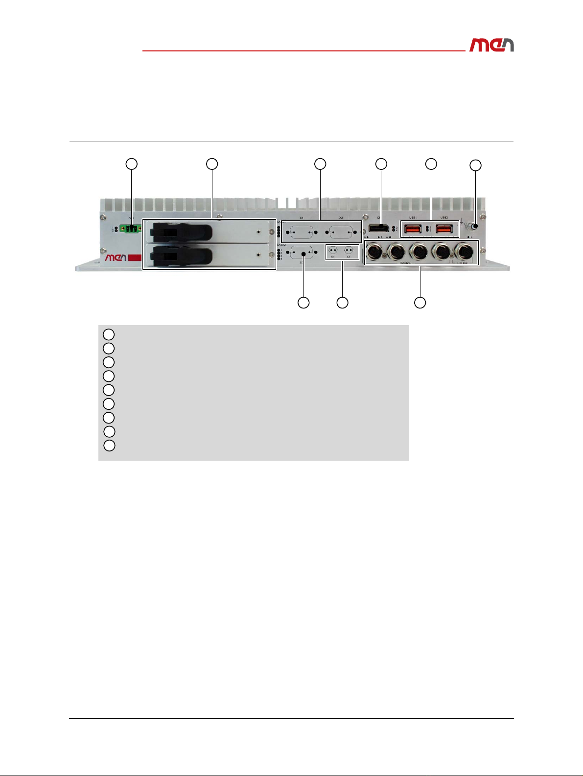
Figure 1. Front interfaces
1
2
3
4
5
6
7
8
2HardDiskShuttles
5GigabitEthernet(4‐portEthernetswitchandoneuplinkport)
2USB2.0
PSUconnector(10V‐50.4V)
1DisplayPort
2antennaconnectorcutoutsforPCIExpressMiniCard
1 2 3 4 5
78
2SA‐AdaptercutoutsforRS232,RS485/422,CAN,IBISmaster,IBISslaveorGPIO
CutoutforHDAudio
6
9
9
Earthingstud
Product Overview
20BL70S00 E3 2018-06-11 Page 13
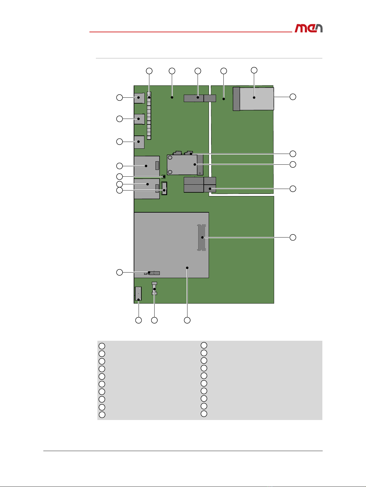
Figure 2. Board layout (PCBs inside the system)
CPUBoard
PCIeMiniCardslot
mSATAslot
PSUconnector
Board‐to‐boardconnector
SDcardslot(onboardbottom)
1
2
3
4
5
6
7
8
9
10
11
12
13
14
15
16
17
18
19
Connectorfor5Ethernetinterfaces
USB interface1
DisplayPort
I/OBoard
SA‐AdaptercutoutforRS232,RS422/485,IBISorCAN
SA‐AdaptercutoutforRS232,RS422/485orIBIS
234
6
9
1012
13
15
16
17
18
19
1
microSIMslot
Connectorforoptionalaudio
SATAconnector
SATAshuttle
Hotplugbutton
20
Clipforfixingantennacable
USB interface2
5
7
8
3
14
11
20
Fuse

Product Overview
20BL70S00 E3 2018-06-11 Page 14
1.2.2 Functions
Figure 3. Functional diagram
F
B
Frontconnector
Onboard connector
SA SA‐Adapter™
RRearI/O connector
Options
HDAudio
Gigabit
Ethernet
Controller
BootFlash
PowerSupply
F
1PCIExpress®
MiniCardSlot
2SIM
CardSlots
F
F
F
2AntennaSlots
F
PCIe
USB2.0
SDCardSlot
B
SATASlot
B
SATASlot
B
CAN
GPIO
SA F
B
UART
UART
SA F
B
FPGA
SwitchDevice
10/100/
1000Base‐T
Port 2
Port 1
Port 3
Port 4
F
F
F
F
GbEth
GbEth
GbEth
GbEth
DisplayPort
B
B
F
mSATASlot
B
USB2.0
USB2.0
Intel®Core™
Processor
4GBECC
DDR3SDRAM
Intel®Platform
ControllerHub
QM77
F
F
GigabitEthernetUplink
Gigabit
Ethernet
Controller

Product Overview
20BL70S00 E3 2018-06-11 Page 15
1.3 Technical Data
CPU
The following CPU types are supported:
-Intel Core i7-3517UE, 2 cores, 4 threads, 1.7 GHz, 2.8 GHz Turbo Boost, 17 W, 4
MB cache
-Intel Core i3-3217UE, 2 cores, 4 threads, 1.6 GHz, 17 W, 3 MB cache
-Intel Celeron 1047UE, 2 cores, 2 threads, 1.4 GHz, 17 W, 2 MB cache
Chipset
-QM77 Platform Controller Hub (PCH)
Memory
System RAM
-Soldered DDR3 with ECC
-16 GB max.
Security
Trusted Platform Module 1.2
Mass Storage
The following mass storage devices can be assembled:
-microSD card
-mSATA
-SSD 2.5" (SATA, via external shuttles)
Graphics
Processor graphics
Maximum resolution: 2560 x 1600 pixels (DisplayPort 1.1a)
Wireless Functionality
Possible wireless functions:
-GNSS
-LTE
-WLAN
Interfaces
Video
-1x DisplayPort
USB
-2x USB 2.0, Type A
Ethernet
-5x 10/100/1000BASE-T, M12 A-coded
-On request: 5x 10/100BASE-T, M12 A-coded
-On request: 4x 10/100BASE-T, M12 A-coded, 1x 10/100/1000BASE-T M12 A-
coded
-Power over Ethernet PSE support on all ports

Product Overview
20BL70S00 E3 2018-06-11 Page 16
PCI Express Mini Card
-1x PCI Express Mini Card slot
-PCIe Full-Mini; PCIe x1, USB 2.0
SIM card
-2x micro-SIM card slot, internally
Power input
-1x power inlet connector
-Ignition input
LED
-Status: board status, power status
-Ethernet: link, activity
-User configurable: 4x
Cutout
-Antenna connector: RP-SMA receptacle, RP-SMA plug, QMA receptacle, QMA
plug, FME receptacle, FME plug
-D-Sub options: Audio, RS232, RS422/RS484, CAN bus, digital I/O, GPS, real-time
Ethernet, Profibus, IBIS slave
Supervision and Control
Board management controller
Watchdog timer
Temperature measurement
Real-time clock, buffered by supercapacitor (3 days)
Electrical Specifications
Supply voltages
-24 V and 36 V nominal input voltage according to EN 50155
-24 V nominal input voltage according to ISO 7637-2 (E-mark) requirements
-Input voltages of 48V, 72V, 110V (on request)
-EN 50155 power interruption class S2
Power consumption
-24 W typ.
Isolation voltage: 1500 VDC against shield
Mechanical Specifications
Dimensions: (W) 390 mm, (D) 215 mm, (H) 66 mm
Weight:
-4.25 kg (model 09BL70S00 in standard housing)
-5.5 kg (model 09BL70S00 in 19" insertion frame)
-
Cooling
-Air cooling, natural convection, airflow 0.4 m/s
See the MEN website for technical product drawings including the
exact dimensions of BL70S:
www.men.de/products/bl70s/#doc

Product Overview
20BL70S00 E3 2018-06-11 Page 17
Protection rating
-IP20
-Other IP protection classes possible on request
Environmental Specifications
Temperature range (operation)
--40°C to 70°C, with up to 85°C for 10 minutes according to class TX (EN 50155)
-Fanless operation
Temperature range (storage): -40°C to +85°C
Relative humidity (operation): max. 95% non-condensing
Relative humidity (storage): max. 95% non-condensing
Altitude: -300 m to +3000 m
Shock: 50 m/s², 30 ms (EN 61373)
Vibration (function): 1 m/s², 5 Hz to 150 Hz (EN 61373)
Vibration (lifetime): 7.9 m/s², 5 Hz to 150 Hz (EN 61373)
Reliability
MTBF: 203 819 h @ 40°C according to IEC/TR 62380 (RDF 2000)(model 09BL70S00)
Safety
Fire Protection
-EN 45545-2 (Railway)
-ECE-R118 (Automotive)
Electrical Safety
-EN 50153
-EN 50155
EMC
Railway
-EN 50121-3-2
Automotive
-ECE R10 (E-mark)
-ISO 10605 (ESD)
BIOS
InsydeH2O UEFI Framework
Software Support
Windows 7
Windows Embedded Standard 7
Linux
See the MEN website for supported operating system versions, available
software and more details on supported functions:
www.men.de/products/bl70s/#downl

Product Overview
20BL70S00 E3 2018-06-11 Page 19
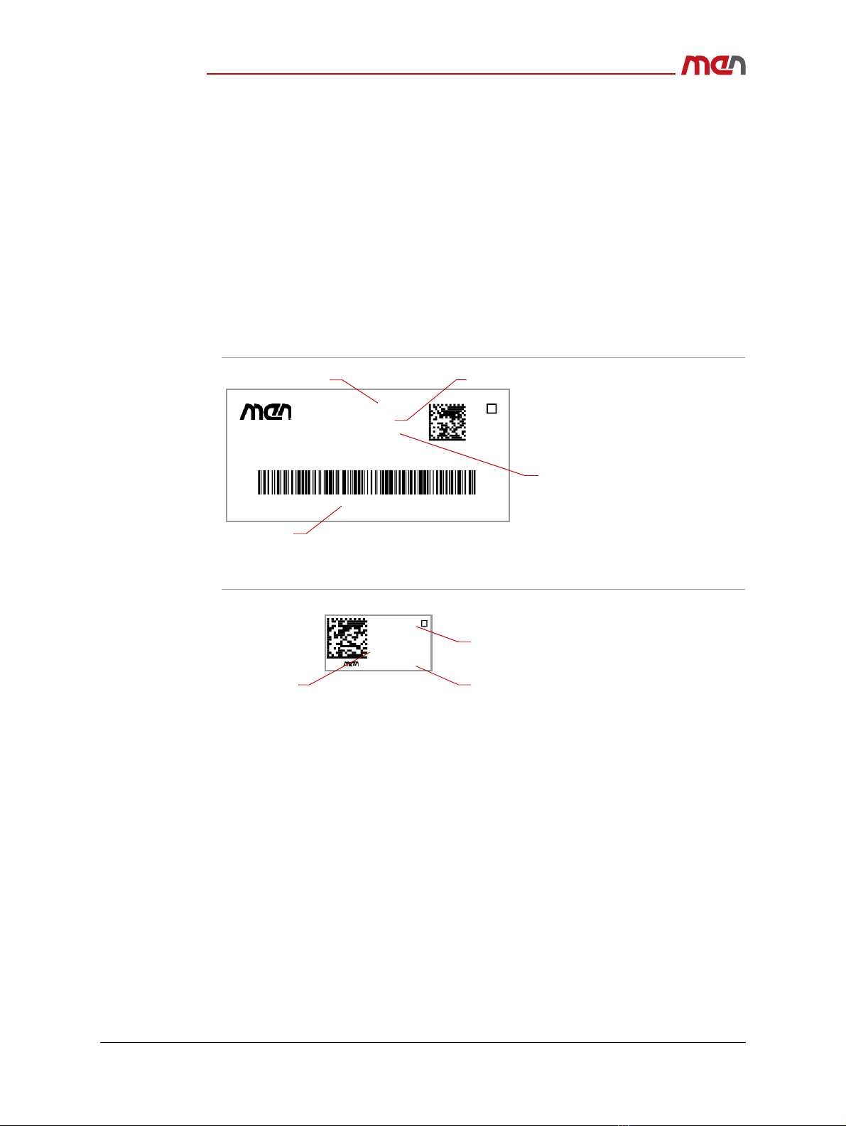
1.5 Product Identification
MEN documentation may describe several different models and design revisions of the
BL70S. You can find the article number, design revision and serial number affixed to the
BL70S.
Article number: Indicates the product family and model. This is also MEN’s main
ordering number. To be complete it must have 9 characters.
Revision number: Indicates the design revision of the product.
Serial number: Unique identification assigned during production.
Ordering key: Unique ordering number of a built-to-order (BTO) configuration.
If you need support, you should communicate these numbers to MEN.
Figure 4. Product label (BTO model)
Figure 5. Product label (non-BTO model)
Serial No.: 000001
Made in Germany
Ordering key:
Rev. No.:
Article No.:
00.00.00
%/6%0
115533TH6588GH872215G63
Revisionnumber
Orderingkey
Basicarticlenumber Serialnumber
Serial No.:
00.00.00
Article No.:
Rev.
09BL0600
000002
RevisionnumberSerialnumber
Completearticlenumber

Getting Started
20BL70S00 E3 2018-06-11 Page 20
2 Getting Started
2.1 Unpacking the BL70S
After unpacking, check whether there are any transport or other damages on the
system. If one of the following situations arises, have the equipment checked by service
personnel:
The power cable or plug is damaged.
Liquid has penetrated into the equipment.
The equipment has been exposed to moisture.
The equipment has been dropped and damaged.
The equipment has obvious signs of breakage.
2.2 Configuring the Hardware
Check your hardware requirements before mounting the BL70S. Modifications are
difficult or impossible to do when the BL70S is mounted.
Electric Shock and Fire Hazard Caused by Damaged Device
Damaged equipment may be under dangerous voltage and can cause fire.
Damaged equipment has unpredictable behavior and characteristics.
Prevent damaged equipment from being installed and put into
operation.
Mark the damaged equipment and keep it under lock and key.
Send the equipment to repair immediately.
Damage from Condensation
When the equipment has been subjected to low temperatures or extreme
temperature variations, condensation can form on or inside the system.
Humidity causes short circuits in electric circuits and damages the system.
To avoid damages, do the following:
Store the equipment in a dry environment.
Ensure that the equipment has the same temperature as the
environment before starting it up.
Do not subject the equipment to the direct radiation of a heating device.
Wait until the equipment has dried completely or wait 12 hours before
switching on the equipment.
MEN offers suitable accessory articles for BL70S.
See the MEN website for ordering information:
www.men.de/products/bl70s/#ord
Table of contents
Other MEN Industrial PC manuals

Popular Industrial PC manuals by other brands


Dell
Dell Embedded Box PC 5000 Installation and operation manual

IBASE Technology
IBASE Technology ASB200-918 Series user manual

Lenovo
Lenovo ThinkCentre M90q Hardware Maintenance Manual

IXXAT
IXXAT Econ 100 Hardware manual

Kontron
Kontron KBox A-151-TGL user guide

AXIOMTEK
AXIOMTEK ICO500-518 Series user manual